2007 ISUZU KB P190 Electrical
[x] Cancel search: ElectricalPage 3594 of 6020
Charging System – V6 Page 6D1-1-7
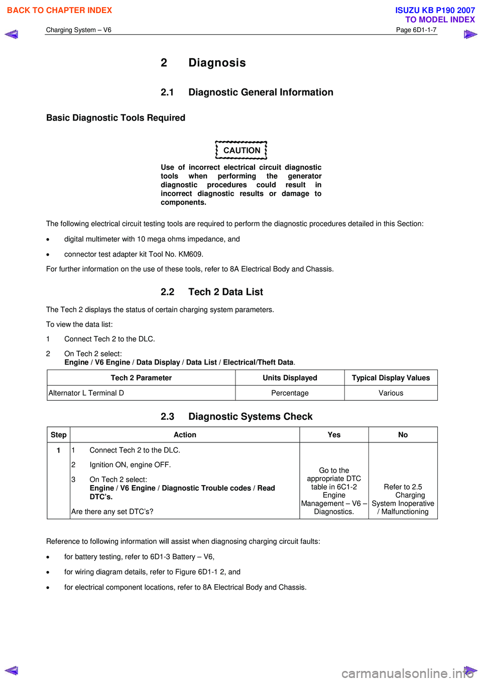
2 Diagnosis
2.1 Diagnostic General Information
Basic Diagnostic Tools Required
Use of incorrect electrical circuit diagnostic
tools when performing the generator
diagnostic procedures could result in
incorrect diagnostic results or damage to
components.
The following electrical circuit testing tools are required to perform the diagnostic procedures detailed in this Section:
• digital multimeter with 10 mega ohms impedance, and
• connector test adapter kit Tool No. KM609.
For further information on the use of these tools, refer to 8A Electrical Body and Chassis.
2.2 Tech 2 Data List
The Tech 2 displays the status of certain charging system parameters.
To view the data list:
1 Connect Tech 2 to the DLC.
2 On Tech 2 select: Engine / V6 Engine / Data Display / Data List / Electrical/Theft Data .
Tech 2 Parameter Units Displayed Typical Display Values
Alternator L Terminal D Percentage Various
2.3 Diagnostic Systems Check
Step Action Yes No
1 1 Connect Tech 2 to the DLC.
2 Ignition ON, engine OFF.
3 On Tech 2 select: Engine / V6 Engine / Diagnostic Trouble codes / Read
DTC’s.
Are there any set DTC’s? Go to the
appropriate DTC table in 6C1-2 Engine
Management – V6 – Diagnostics. Refer to 2.5
Charging
System Inoperative / Malfunctioning
Reference to following information will assist when diagnosing charging circuit faults:
• for battery testing, refer to 6D1-3 Battery – V6,
• for wiring diagram details, refer to Figure 6D1-1 2, and
• for electrical component locations, refer to 8A Electrical Body and Chassis.
BACK TO CHAPTER INDEX
TO MODEL INDEX
ISUZU KB P190 2007
Page 3596 of 6020
Charging System – V6 Page 6D1-1-9
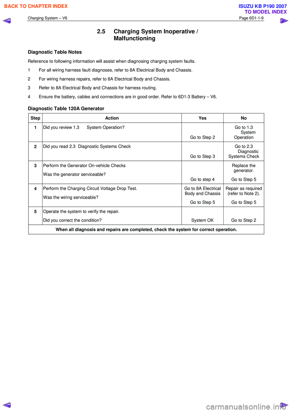
2.5 Charging System Inoperative /
Malfunctioning
Diagnostic Table Notes
Reference to following information will assist when diagnosing charging system faults.
1 For all wiring harness fault diagnoses, refer to 8A Electrical Body and Chassis.
2 For wiring harness repairs, refer to 8A Electrical Body and Chassis.
3 Refer to 8A Electrical Body and Chassis for harness routing.
4 Ensure the battery, cables and connections are in good order. Refer to 6D1-3 Battery – V6.
Diagnostic Table 120A Generator
Step Action Yes No
1 Did you review 1.3 System Operation?
Go to Step 2 Go to 1.3
System Operation
2 Did you read 2.3 Diagnostic Systems Check
Go to Step 3 Go to 2.3
Diagnostic
Systems Check
3 Perform the Generator On-vehicle Checks
W as the generator serviceable? Go to step 4 Replace the
generator.
Go to Step 5
4 Perform the Charging Circuit Voltage Drop Test.
W as the wiring serviceable? Go to 8A Electrical
Body and Chassis
Go to Step 5 Repair as required
(refer to Note 2).
Go to Step 5
5 Operate the system to verify the repair.
Did you correct the condition? System OK Go to Step 2
When all diagnosis and repairs are completed, check the system for correct operation.
BACK TO CHAPTER INDEX
TO MODEL INDEX
ISUZU KB P190 2007
Page 3598 of 6020
Charging System – V6 Page 6D1-1-11
3.3 On-vehicle Testing
Generator On-vehicle Checks
Prerequisites
Before testing the generator output, ensure that:
• all generator circuit connections are clean and tight,
• the generator is always connected to the battery during testing (to prevent damage to the diodes),
• the battery is fully charged, and
• the specific gravity does not vary more than 0.025 between cells. (It is recommended the average specific gravity
is 1.260 or higher). Refer to 6D1-3 Battery – V6.
Carry out a load test on the battery to determine its ability to supply and accept current. This is a good indicator of the
general condition of the battery. For details of battery testing, refer to 6D1-3 Battery – V6.
Inspect the drive belt and tensioner markings to determine if the drive belt is within operating limits. Replace the belt if it
is excessively worn or outside the operating range of the tensioner.
For further details, refer to 6A1 Engine Mechanical – V6.
Generator Test
Regulating Voltage Test
NOTE
Leave the generator E-4 wiring harness
connector connected, as it provides initial field
excitation.
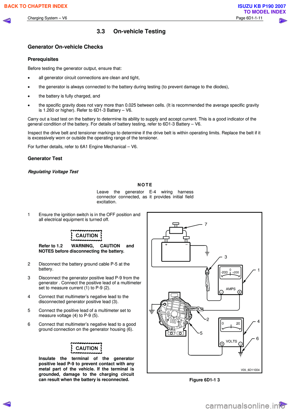
1 Ensure the ignition switch is in the OFF position and all electrical equipment is turned off.
Refer to 1.2 WARNING, CAUTION and
NOTES before disconnecting the battery.
2 Disconnect the battery ground cable P-5 at the battery.
3 Disconnect the generator positive lead P-9 from the generator . Connect the positive lead of a multimeter
set to measure current (1) to P-9 (2).
4 Connect that multimeter’s negative lead to the disconnected generator positive lead (3).
5 Connect the positive lead of a multimeter set to measure voltage (4) to P-9 (5).
6 Connect that multimeter’s negative lead to a good ground connection on the generator housing (6).
Insulate the terminal of the generator
positive lead P-9 to prevent contact with any
metal part of the vehicle. If the terminal is
grounded, damage to the charging circuit
can result when the battery is reconnected.
Figure 6D1-1 3
BACK TO CHAPTER INDEX
TO MODEL INDEX
ISUZU KB P190 2007
Page 3601 of 6020

Charging System – V6 Page 6D1-1-14
8 Connect the positive lead of a multimeter set to measure voltage to the battery negative post.
9 Connect the negative lead of the multimeter to the generator housing.
9 Increase the engine speed to approximately 2500 r.p.m.
10 Record the voltage reading.
11 Reduce the engine speed to idle.
12 Check the two readings. If the readings exceed 0.3 V, there is a high resistance in the charging circuit.
13 Trace the cause and correct the problem, refer to 8A Electrical Body and Chassis.
BACK TO CHAPTER INDEX
TO MODEL INDEX
ISUZU KB P190 2007
Page 3602 of 6020

Charging System – V6 Page 6D1-1-15
4 Major Service Operations
4.1 Generator
Remove
Refer to 1.2 WARNING, CAUTION and NOTES
before disconnecting the battery.
1 Disconnect the battery ground lead P-5. Refer to 8A Electrical Body and Chassis.
2 Insert a ½ inch drive socket bar into the tensioner arm and rotate the tensioner arm clockwise.
3 Remove the drive belt from the generator pulley and release the tensioner. Refer to 6A1 Engine Mechanical – V6 for further details as required.
4 Pull the battery harness cap back from generator terminal P-9 (3), remove the nut (4) and remove the
positive lead (2) from the generator (5).
5 Disengage the connector retaining clip and remove the connector E-4, (1) from the generator.
Figure 6D1-1 4
6 Remove the three bolts (1, 2, 4) retaining the generator (3) to the generator bracket.
7 Remove the generator assembly from the vehicle.
Figure 6D1-1 5
BACK TO CHAPTER INDEX
TO MODEL INDEX
ISUZU KB P190 2007
Page 3608 of 6020
Charging System – V6 Page 6D1-1-21
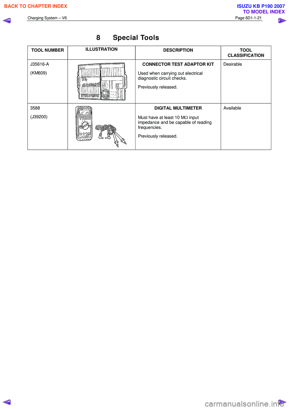
8 Special Tools
TOOL NUMBER ILLUSTRATION
DESCRIPTION TOOL
CLASSIFICATION
J35616-A
(KM609)
CONNECTOR TEST ADAPTOR KIT
Used when carrying out electrical
diagnostic circuit checks.
Previously released. Desirable
3588
(J39200)
DIGITAL MULTIMETER
Must have at least 10 M Ω input
impedance and be capable of reading
frequencies.
Previously released. Available
BACK TO CHAPTER INDEX
TO MODEL INDEX
ISUZU KB P190 2007
Page 3615 of 6020
Starting System – V6 Page 6D1-2–7
2 Diagnostics
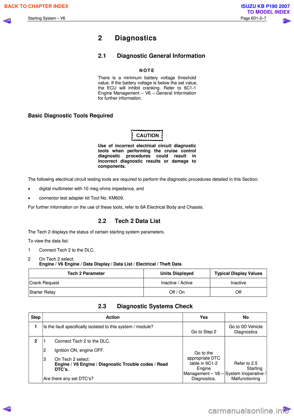
2.1 Diagnostic General Information
NOTE
There is a minimum battery voltage threshold
value. If the battery voltage is below the set value,
the ECU will inhibit cranking. Refer to 6C1-1
Engine Management – V6 – General Information
for further information.
Basic Diagnostic Tools Required
Use of incorrect electrical circuit diagnostic
tools when performing the cruise control
diagnostic procedures could result in
incorrect diagnostic results or damage to
components.
The following electrical circuit testing tools are required to perform the diagnostic procedures detailed in this Section:
• digital multimeter with 10 meg ohms impedance, and
• connector test adapter kit Tool No. KM609.
For further information on the use of these tools, refer to 8A Electrical Body and Chassis.
2.2 Tech 2 Data List
The Tech 2 displays the status of certain starting system parameters.
To view the data list:
1 Connect Tech 2 to the DLC.
2 On Tech 2 select: Engine / V6 Engine / Data Display / Data List / Electrical / Theft Data .
Tech 2 Parameter Units Displayed Typical Display Values
Crank Request Inactive / Active Inactive
Starter Relay Off / On Off
2.3 Diagnostic Systems Check
Step Action Yes No
1
Is the fault specifically isolated to this system / module?
Go to Step 2 Go to 0D Vehicle
Diagnostics
2 1 Connect Tech 2 to the DLC.
2 Ignition ON, engine OFF.
3 On Tech 2 select:
Engine / V6 Engine / Diagnostic Trouble codes / Read
DTC’s.
Are there any set DTC’s? Go to the
appropriate DTC
table in 6C1-2 Engine
Management – V6 – Diagnostics. Refer to 2.5
Starting
System Inoperative / Malfunctioning
BACK TO CHAPTER INDEX
TO MODEL INDEX
ISUZU KB P190 2007
Page 3618 of 6020
Starting System – V6 Page 6D1-2–10
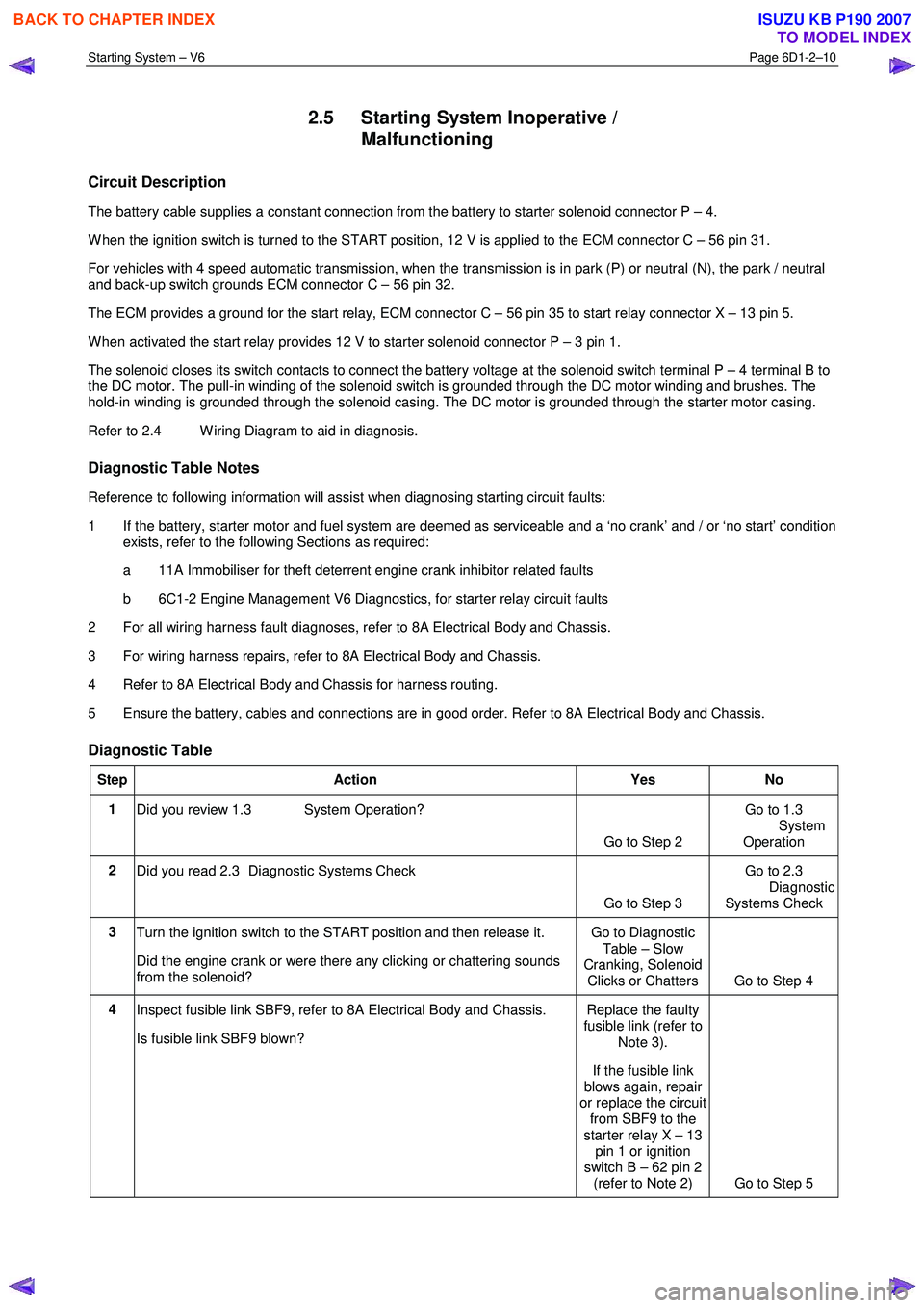
2.5 Starting System Inoperative /
Malfunctioning
Circuit Description
The battery cable supplies a constant connection from the battery to starter solenoid connector P – 4.
W hen the ignition switch is turned to the START position, 12 V is applied to the ECM connector C – 56 pin 31.
For vehicles with 4 speed automatic transmission, when the transmission is in park (P) or neutral (N), the park / neutral
and back-up switch grounds ECM connector C – 56 pin 32.
The ECM provides a ground for the start relay, ECM connector C – 56 pin 35 to start relay connector X – 13 pin 5.
W hen activated the start relay provides 12 V to starter solenoid connector P – 3 pin 1.
The solenoid closes its switch contacts to connect the battery voltage at the solenoid switch terminal P – 4 terminal B to
the DC motor. The pull-in winding of the solenoid switch is grounded through the DC motor winding and brushes. The
hold-in winding is grounded through the solenoid casing. The DC motor is grounded through the starter motor casing.
Refer to 2.4 W iring Diagram to aid in diagnosis.
Diagnostic Table Notes
Reference to following information will assist when diagnosing starting circuit faults:
1 If the battery, starter motor and fuel system are deemed as serviceable and a ‘no crank’ and / or ‘no start’ condition exists, refer to the following Sections as required:
a 11A Immobiliser for theft deterrent engine crank inhibitor related faults
b 6C1-2 Engine Management V6 Diagnostics, for starter relay circuit faults
2 For all wiring harness fault diagnoses, refer to 8A Electrical Body and Chassis.
3 For wiring harness repairs, refer to 8A Electrical Body and Chassis.
4 Refer to 8A Electrical Body and Chassis for harness routing.
5 Ensure the battery, cables and connections are in good order. Refer to 8A Electrical Body and Chassis.
Diagnostic Table
Step Action Yes No
1
Did you review 1.3 System Operation?
Go to Step 2 Go to 1.3
System
Operation
2 Did you read 2.3 Diagnostic Systems Check
Go to Step 3 Go to 2.3
Diagnostic Systems Check
3 Turn the ignition switch to the START position and then release it.
Did the engine crank or were there any clicking or chattering sounds
from the solenoid? Go to Diagnostic
Table – Slow
Cranking, Solenoid Clicks or Chatters Go to Step 4
4 Inspect fusible link SBF9, refer to 8A Electrical Body and Chassis.
Is fusible link SBF9 blown? Replace the faulty
fusible link (refer to
Note 3).
If the fusible link
blows again, repair
or replace the circuit from SBF9 to the
starter relay X – 13 pin 1 or ignition
switch B – 62 pin 2 (refer to Note 2) Go to Step 5
BACK TO CHAPTER INDEX
TO MODEL INDEX
ISUZU KB P190 2007