2007 ISUZU KB P190 Electrical
[x] Cancel search: ElectricalPage 3502 of 6020
Engine Management – V6 – Diagnostics Page 6C1-2–224
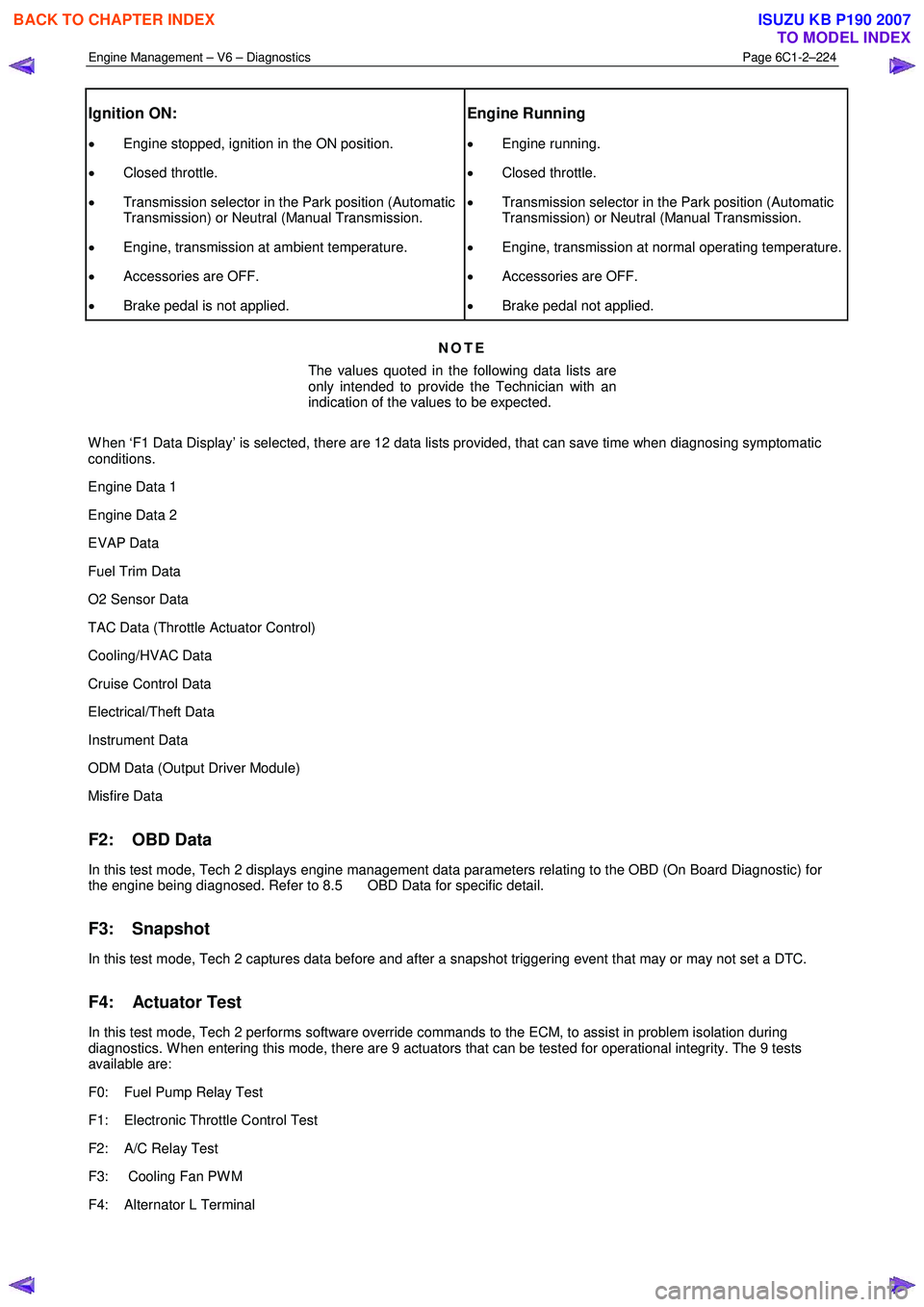
Ignition ON:
• Engine stopped, ignition in the ON position.
• Closed throttle.
• Transmission selector in the Park position (Automatic
Transmission) or Neutral (Manual Transmission.
• Engine, transmission at ambient temperature.
• Accessories are OFF.
• Brake pedal is not applied.
Engine Running
• Engine running.
• Closed throttle.
• Transmission selector in the Park position (Automatic
Transmission) or Neutral (Manual Transmission.
• Engine, transmission at normal operating temperature.
• Accessories are OFF.
• Brake pedal not applied.
NOTE
The values quoted in the following data lists are
only intended to provide the Technician with an
indication of the values to be expected.
W hen ‘F1 Data Display’ is selected, there are 12 data lists provided, that can save time when diagnosing symptomatic
conditions.
Engine Data 1
Engine Data 2
EVAP Data
Fuel Trim Data
O2 Sensor Data
TAC Data (Throttle Actuator Control)
Cooling/HVAC Data
Cruise Control Data
Electrical/Theft Data
Instrument Data
ODM Data (Output Driver Module)
Misfire Data
F2: OBD Data
In this test mode, Tech 2 displays engine management data parameters relating to the OBD (On Board Diagnostic) for
the engine being diagnosed. Refer to 8.5 OBD Data for specific detail.
F3: Snapshot
In this test mode, Tech 2 captures data before and after a snapshot triggering event that may or may not set a DTC.
F4: Actuator Test
In this test mode, Tech 2 performs software override commands to the ECM, to assist in problem isolation during
diagnostics. W hen entering this mode, there are 9 actuators that can be tested for operational integrity. The 9 tests
available are:
F0: Fuel Pump Relay Test
F1: Electronic Throttle Control Test
F2: A/C Relay Test
F3: Cooling Fan PW M
F4: Alternator L Terminal
BACK TO CHAPTER INDEX
TO MODEL INDEX
ISUZU KB P190 2007
Page 3513 of 6020
Engine Management – V6 – Diagnostics Page 6C1-2–235
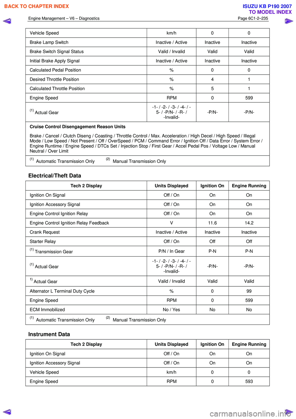
Vehicle Speed km/h 0 0
Brake Lamp Switch Inactive / Active Inactive Inactive
Brake Switch Signal Status Valid / Invalid Valid Valid
Initial Brake Apply Signal Inactive / Active Inactive Inactive
Calculated Pedal Position % 0 0
Desired Throttle Position % 4 1
Calculated Throttle Position % 5 1
Engine Speed RPM 0 599
(1) Actual Gear -1- / -2- / -3- / -4- / -
5- / -P/N- / -R- / -Invalid- -P/N- -P/N-
Cruise Control Disengagement Reason Units
Brake / Cancel / Clutch Diseng / Coasting / Throttle Control / Max. Acceleration / High Decel / High Speed / Illegal
Mode / Low Speed / Not Present / Off / OverSpeed / PCM / Command Error / Ignition Off / Data Error / System Error /
Engine Runtime / Engine Speed / DTCs Set / Injection Stop / First Gear / Accel Pedal Pos / Voltage Low / Manual
Neutral / Over Limit
(1) Automatic Transmission Only (2) Manual Transmission Only
Electrical/Theft Data
Tech 2 Display Units Displayed Ignition On Engine Running
Ignition On Signal Off / On On On
Ignition Accessory Signal Off / On On On
Engine Control Ignition Relay Off / On On On
Engine Control Ignition Relay Feedback V 11.6 14.2
Crank Request Inactive / Active Inactive Inactive
Starter Relay Off / On Off Off
(1) Transmission Gear P/N / In Gear P-N P-N
(1) Actual Gear -1- / -2- / -3- / -4- / -
5- / -P/N- / -R- / -Invalid- -P/N- -P/N-
1) Actual Gear
Valid / Invalid Valid
Valid
Alternator L Terminal Duty Cycle % 0 99
Engine Speed RPM 0 599
ECM Immobilized No / Yes No No
(1) Automatic Transmission Only (2) Manual Transmission Only
Instrument Data
Tech 2 Display Units Displayed Ignition On Engine Running
Ignition On Signal Off / On On On
Ignition Accessory Signal Off / On On On
Vehicle Speed km/h 0 0
Engine Speed RPM 0 593
BACK TO CHAPTER INDEX
TO MODEL INDEX
ISUZU KB P190 2007
Page 3525 of 6020
Engine Management – V6 – Service Operations Page 6C1-3–1
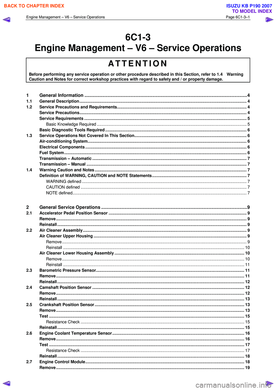
6C1-3
Engine Management – V6 – Service Operations
ATTENTION
Before performing any service operation or other procedure described in this Section, refer to 1.4 Warning
Caution and Notes for correct workshop practices with regard to safety and / or property damage.
1 General Information ............................................................................................................ ...................4
1.1 General Description ............................................................................................................ ................................... 4
1.2 Service Precautions and Requirements........................................................................................... .................... 4
Service Precautions............................................................................................................................................... 4
Service Requirements ........................................................................................................................................... 5
Basic Knowledge Required ....................................................................................................... ......................... 5
Basic Diagnostic Tools Required ......................................................................................................................... 6
1.3 Service Operations Not Covered In This Section................................................................................. ............... 6
Air-conditioning System........................................................................................................................................ 6
Electrical Components .......................................................................................................................................... 6
Fuel System ............................................................................................................................................................ 6
Transmission – Automatic ....................................................................................................... ............................. 7
Transmission – Manual ......................................................................................................................................... 7
1.4 Warning Caution and Notes .................................................................................................................................. 7
Definition of WARNING, CAUTION and NOTE Statements ............................................................................. .... 7
WARNING defined ............................................................................................................................................. 7
CAUTION defined .............................................................................................................................................. 7
NOTE defined..................................................................................................................................................... 7
2 General Service Operations ..................................................................................................... .............9
2.1 Accelerator Pedal Position Sensor .............................................................................................. ........................ 9
Remove ................................................................................................................................................................... 9
Reinstall .................................................................................................................................................................. 9
2.2 Air Cleaner Assembly ............................................................................................................................................ 9
Air Cleaner Upper Housing ...................................................................................................... ............................. 9
Remove .............................................................................................................................................................. 9
Reinstall ........................................................................................................................................................... 10
Air Cleaner Lower Housing Assembly ............................................................................................. .................. 10
Remove ............................................................................................................................................................ 10
Reinstall ........................................................................................................................................................... 11
2.3 Barometric Pressure Sensor..................................................................................................... .......................... 11
Remove ................................................................................................................................................................. 11
Reinstall ................................................................................................................................................................ 12
2.4 Camshaft Position Sensor ....................................................................................................... ........................... 12
Remove ................................................................................................................................................................. 12
Reinstall ................................................................................................................................................................ 13
2.5 Crankshaft Position Sensor ..................................................................................................... ........................... 13
Remove ................................................................................................................................................................. 13
Test ....................................................................................................................................................................... 15
Resistance Check ............................................................................................................... ............................. 15
Reinstall ................................................................................................................................................................ 15
2.6 Engine Coolant Temperature Sensor .............................................................................................. ................... 16
Remove ................................................................................................................................................................. 16
Test ....................................................................................................................................................................... 17
Resistance Check ............................................................................................................... ............................. 17
Reinstall ................................................................................................................................................................ 18
2.7 Engine Control Module.......................................................................................................... .............................. 18
Remove ................................................................................................................................................................. 19
BACK TO CHAPTER INDEX
TO MODEL INDEX
ISUZU KB P190 2007
Page 3529 of 6020
Engine Management – V6 – Service Operations Page 6C1-3–5
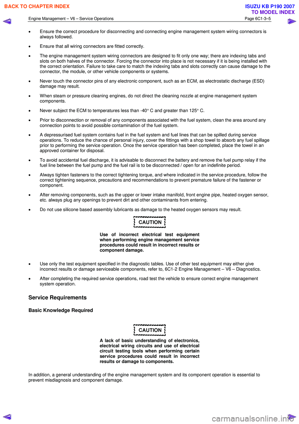
• Ensure the correct procedure for disconnecting and connecting engine management system wiring connectors is
always followed.
• Ensure that all wiring connectors are fitted correctly.
• The engine management system wiring connectors are designed to fit only one way; there are indexing tabs and
slots on both halves of the connector. Forcing the connector into place is not necessary if it is being installed with
the correct orientation. Failure to take care to match the indexing tabs and slots correctly can cause damage to the
connector, the module, or other vehicle components or systems.
• Never touch the connector pins of any electronic component, such as an ECM, as electrostatic discharge (ESD)
damage may result.
• W hen steam or pressure cleaning engines, do not direct the cleaning nozzle at engine management system
components.
• Never subject the ECM to temperatures less than -40 ° C and greater than 125 ° C.
• Prior to disconnection or removal of any components associated with the fuel system, clean the area around any
connection points to avoid possible contamination of the fuel system.
• A depressurised fuel system contains fuel in the fuel system and fuel lines that can be spilled during service
operations. To reduce the chance of personal injury, cover the fittings with a shop towel to absorb any fuel spillage
prior to performing the service operation. Once the service operation has been completed, place the towel in an
approved container for disposal.
• To avoid accidental fuel discharge, it is advisable to disconnect the battery and remove the fuel pump relay if the
fuel line between the fuel pump and the fuel rail is to be disconnected / open for an indefinite period.
• Always tighten fasteners to the correct tightening torque, and where indicated in the service procedure, follow the
correct tightening sequence, precautions and recommendations to prevent premature failure of the fastener or
component.
• After removing components, such as the upper or lower intake manifold, front engine pipe, heated oxygen sensor,
etc. always plug any openings to prevent dirt and other contaminants from entering.
• Do not use silicone based assembly lubricants as damage to the heated oxygen sensors may result.
Use of incorrect electrical test equipment
when performing engine management service
procedures could result in incorrect results or
component damage.
• Use only the test equipment specified in the diagnostic tables. Use of other test equipment may either give
incorrect results or damage serviceable components, refer to, 6C1-2 Engine Management – V6 – Diagnostics.
• After completing the required service operations, road test the vehicle to ensure correct engine management
system operation.
Service Requirements
Basic Knowledge Required
A lack of basic understanding of electronics,
electrical wiring circuits and use of electrical
circuit testing tools when performing certain
service procedures could result in incorrect
results or damage to components.
In addition, a general understanding of the engine management system and its component operation is essential to
prevent misdiagnosis and component damage.
BACK TO CHAPTER INDEX
TO MODEL INDEX
ISUZU KB P190 2007
Page 3530 of 6020
Engine Management – V6 – Service Operations Page 6C1-3–6
Basic Diagnostic Tools Required
Use of incorrect electrical circuit diagnostic
tools when performing certain service
procedures could result in incorrect
diagnostic results or damage to components.
The following electrical circuit testing tools are required to perform the diagnostic procedures detailed in this Section:
• Test lamp, refer to 8A Electrical – Body and Chassis for further information.
• Digital multimeter with 10 M Ω ohms impedance, refer to 8A Electrical – Body and Chassis for further information.
• Connector test adapter kit Tool No. J35616-A.
1.3 Service Operations Not Covered In This
Section
There are situations where components and/or procedures related to the powertrain management system are covered in
other Sections of the service documentation. To aid technicians in locating the necessary service procedures for these
components and/or procedures, refer to the stated references.
Air-conditioning System
For A/C pressure switch replacement procedure, refer to 2A Heater and Air-conditioning.
Electrical Components
For the following electrical system component replacement procedures, refer to the appropriate Sections as follows:
• Extended brake pedal travel switch and stop lamp switch service operations, refer to 5C Brakes.
• Fuse and relay locations, refer to 8A Electrical-Body and Chassis.
• Cruise control switch assembly service operations, refer to 8C Cruise Control – HFV6.
• Powertrain interface module PIM removal and installation procedure, refer to 6E1 Powertrain Interface Module – V6.
• Neutral start and back-up lamp switch, refer to 7C4 Automatic Transmission – 4L60E – On-vehicle Servicing.
• Vehicle speed sensor service operations, refer to:
− 7C4 Automatic Transmission – 4L60E – On-vehicle Servicing
− 7B1 Manual Transmission – V6
Fuel System
For the following fuel system component replacement procedures, refer to 6C Fuel System – V6.
• Fuel system cleaning,
• Fuel system leak and pressure test,
• Fuel feed hose to fuel rail replacement,
• Fuel line quick connect fittings,
• Evaporative emission control canister,
• Fuel filter,
• Fuel hose / pipes layout,
• Fuel pump motor assembly and fuel pressure regulator assembly,
• Fuel sender assembly service operations.
BACK TO CHAPTER INDEX
TO MODEL INDEX
ISUZU KB P190 2007
Page 3576 of 6020
Engine Management – V6 – Service Operations Page 6C1-3–52
Oil Fouled (3)
W et, oily deposits with minor electrode wear possibly due to oil leaking past worn piston rings.
Breaking in a new or recently overhauled engine before the rings are fully seated may also result in this condition.
Deposit Fouling A (4)
Red brown, yellow and white coloured coatings on the insulator tip which are by-products of combustion. They come
from fuel and lubricating oil which generally contain additives. Most powdery deposits have no adverse effect on spark
plug operation, however, they may cause intermittent missing under severe operating conditions.
Deposit Fouling B (5)
Deposits similar to those identified in deposit fouling A (4). These are also by-products of combustion from fuel and
lubricating oil. Excessive valve stem clearances and / or defective intake valve seals allow too much oil to enter the
combustion chamber. The deposits will accumulate on the portion of the spark plug that projects into the chamber and
will be heaviest on the side facing the intake valve. If this condition is only detected in one or two cylinders, check the
valve stem seals.
Deposit Fouling C (6)
Most powdery deposits identified in deposit fouling A (4) have no adverse effect on the operation of the spark plug as
long as they remain powdery.
Under certain conditions of operation however, these deposits melt and form a shiny glaze coating on the insulator.
W hen hot, this acts as a good electrical conductor allowing the current to flow along the deposit instead of sparking
across the gap.
Detonation (7)
Commonly referred to as engine knock or pinging, detonation causes severe shocks inside the combustion chamber
causing damage to parts.
Pre-ignition (8)
Burnt or blistered insulator tip and badly eroded electrodes probably due to the excessive heat.
This is often caused by a cooling system blockage, sticking valves, improperly installed spark plugs or plugs that are the
wrong heat rating (too hot).
Sustained high speed with a heavy load can produce temperatures high enough to cause pre-ignition.
Heat Shock Failure (9)
A rapid increase in spark plug tip temperature under severe operating conditions can cause heat shock and result in
fractured insulators. This is a common cause of broken and cracked insulator tips.
Insufficient Installation Torque (10)
Poor contact between the spark plug and the cylinder head seat.
The lack of proper heat transfer that results from poor seat contact causes overheating of the spark plug. In many cases,
severe damage occurs. Dirty threads in the cylinder head can cause the plug to seize before it is seated.
Ensure the cylinder head and spark plug threads are free of deposits, burrs and scale before installation.
BACK TO CHAPTER INDEX
TO MODEL INDEX
ISUZU KB P190 2007
Page 3586 of 6020

Engine Management – V6 – Service Operations Page 6C1-3–62
6 Special Tools
Tool Number Illustration Description Tool Classification
7000086i
Tech 2 scan tool
Used for diagnosis of vehicle electrical
systems.
Previously released. Mandatory
3588
Digital Multimeter
Previously released as j 39200, 3545
GM. Available
J 35616
Connector Test Adaptor Kit
Used when carrying out electrical
diagnostic circuit checks.
Previously released. Desirable
J 34142-a
Un-powered Test Lamp
Previously released as CT-40-C and
also commercially available.
Must have a current draw less than
0.3 A. Mandatory
J 34730-2C
Injector Test Light
Used to check for power and the
control circuit of the fuel injector, for
proper operation.
Also previously released as
ST- 8329 Mandatory
J 39021 Fuel Injector Coil / Balance Tester
Used in conjunction with a DMM for
testing the fuel injector coil windings
and for injector balance testing.
Previously released Mandatory
J 44602 Injector Test Adapter
Mandatory
BACK TO CHAPTER INDEX
TO MODEL INDEX
ISUZU KB P190 2007
Page 3593 of 6020
Charging System – V6 Page 6D1-1-6
Alternator Warning
NOTE
All generator faults are displayed as
Check Alternator W arning on the instrument
cluster MFD, refer to 8A Electrical Body and
Chassis.
The ECM monitors the voltage on connector E-60 pin 21 and pin 43.
The voltage at the generator connector E-4 pin 2 will remain low when a fault condition is detected in the generator or
associated external circuits. The voltage remains low (while the ignition switch is on) until the fault is repaired.
NOTE
For more information on the alternator warning
refer to 8A Electrical Body and Chassis.
Fault conditions include the following:
• open circuit or excessive voltage drop in circuit 1,
• open circuit in the generator phase connection,
• overcharging conditions,
• short circuit in the regulator output stage,
• open circuit in the rotor winding,
• poor contact between the rectifier and the regulator, and / or
• high resistance in the fusible link assembly.
BACK TO CHAPTER INDEX
TO MODEL INDEX
ISUZU KB P190 2007