2007 ISUZU KB P190 turn signal
[x] Cancel search: turn signalPage 5304 of 6020
8A-366 ELECTRICAL-BODY AND CHASSIS
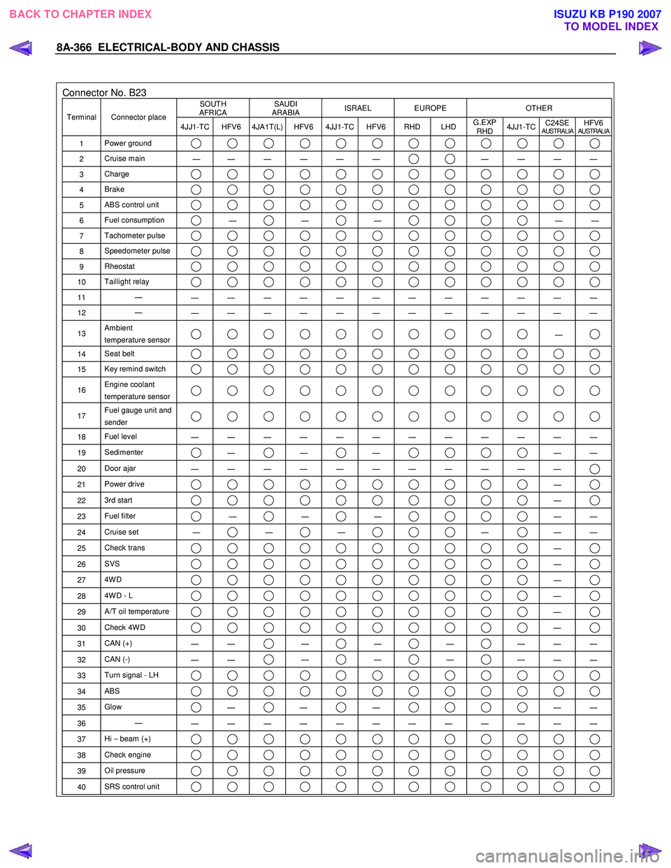
Connector No. B23 SOUTH
AFRICA SAUDI
ARABIA ISRAEL EUROPE OTHER
Terminal Connector place
4JJ1-TC HFV6 4JA1T(L) HFV6 4JJ1-TC HFV6 RHD LHD G.EXP
RHD 4JJ1-TC
C24SE
AUSTRALIAHFV6AUSTRALIA
1
Power ground
2 Cruise main
―
― ― ― ― ― ― ― ― ―
3
Charge
4 Brake
5 ABS control unit
6 Fuel consumption ―
―
―
―
―
7 Tachometer pulse
8 Speedometer pulse
9 Rheostat
10 Taillight relay
11 ―
― ― ― ― ― ― ― ― ― ― ― ―
12 ―
― ― ― ― ― ― ― ― ― ― ― ―
13 Ambient
temperature sensor ―
14 Seat belt
15 Key remind switch
16 Engine coolant
temperature sensor
17 Fuel gauge unit and
sender
18 Fuel level
― ― ― ― ― ― ― ― ― ― ― ―
19 Sedimenter ―
―
―
―
―
20 Door ajar
― ― ― ― ― ― ― ― ― ― ―
21 Power drive ―
22 3rd start ―
23 Fuel filter ―
―
―
―
―
24 Cruise set
― ―
―
―
―
―
25 Check trans ―
26 SVS ―
27 4W D ―
28 4W D - L ―
29 A/T oil temperature ―
30 Check 4W D ―
31 CAN (+)
― ― ―
―
―
― ― ―
32
CAN (-)
― ― ―
―
―
― ― ―
33
Turn signal - LH
34 ABS
35 Glow ―
―
―
―
―
36 ―
― ― ― ― ― ― ― ― ― ― ― ―
37 Hi – beam (+)
38 Check engine
39 Oil pressure
40 SRS control unit
BACK TO CHAPTER INDEX
TO MODEL INDEXISUZU KB P190 2007
Page 5305 of 6020
ELECTRICAL-BODY AND CHASSIS 8A-367
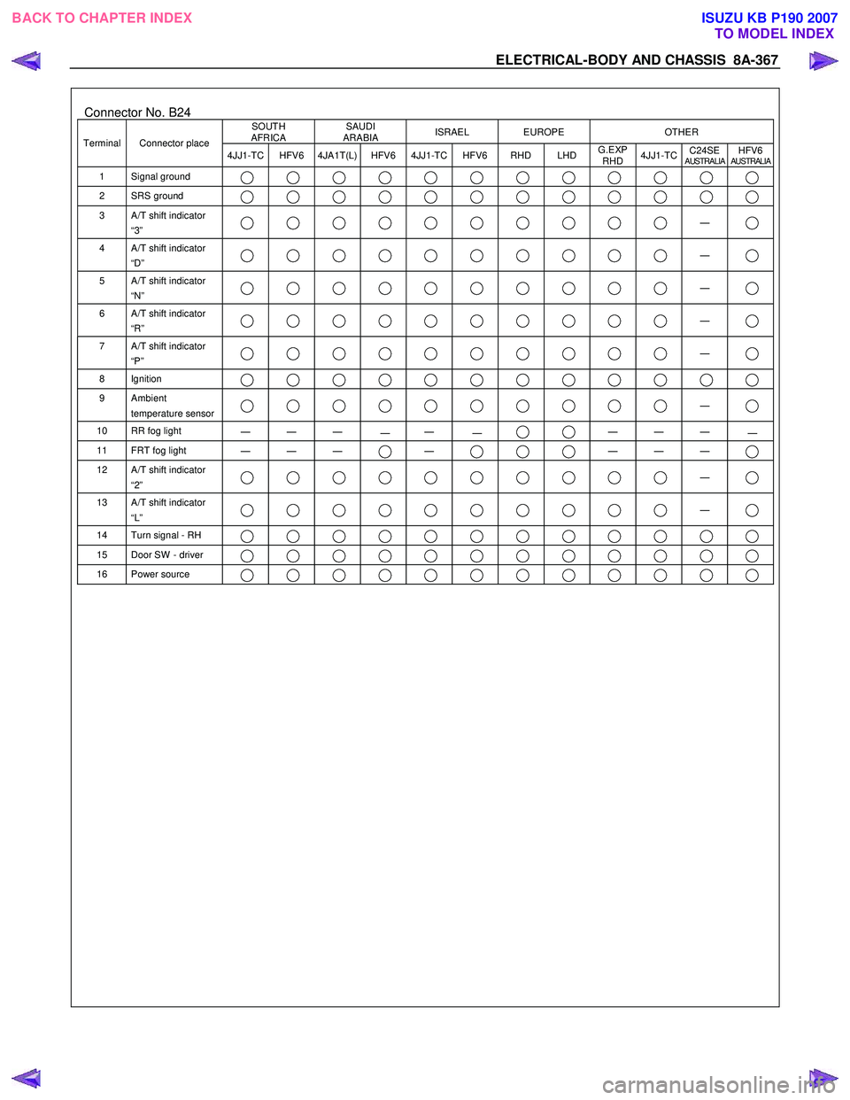
Connector No. B24 SOUTH
AFRICA SAUDI
ARABIA ISRAEL EUROPE OTHER
Terminal Connector place
4JJ1-TC HFV6 4JA1T(L) HFV6 4JJ1-TC HFV6 RHD LHD G.EXP
RHD 4JJ1-TC
C24SE
AUSTRALIAHFV6AUSTRALIA
1 Signal ground
2 SRS ground
3 A/T shift indicator
“3” ―
4 A/T shift indicator
“D” ―
5 A/T shift indicator
“N” ―
6 A/T shift indicator
“R” ―
7 A/T shift indicator
“P” ―
8 Ignition
9 Ambient
temperature sensor ―
10 RR fog light
― ― ― ― ― ―
―
― ― ―
11 FRT fog light
― ― ― ― ―
― ―
12 A/T shift indicator
“2” ―
13 A/T shift indicator
“L” ―
14 Turn signal - RH
15 Door SW - driver
16 Power source
BACK TO CHAPTER INDEX TO MODEL INDEXISUZU KB P190 2007
Page 5523 of 6020
ELECTRICAL-BODY AND CHASSIS 8A-585
RTW 38DSH001701
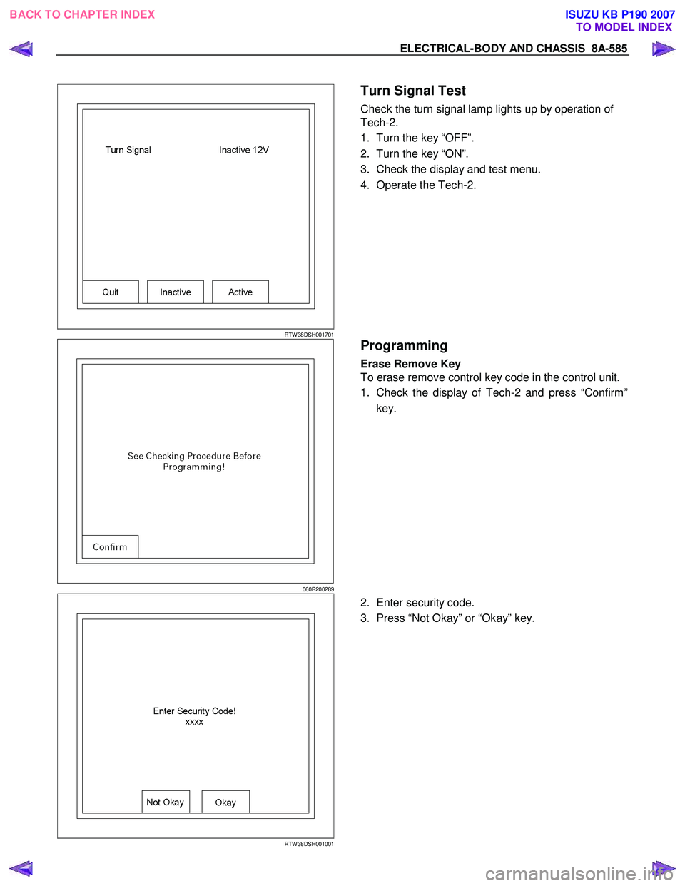
Turn Signal Test
Check the turn signal lamp lights up by operation of
Tech-2.
1. Turn the key “OFF”.
2. Turn the key “ON”.
3. Check the display and test menu.
4. Operate the Tech-2.
060R200289
Programming
Erase Remove Key
To erase remove control key code in the control unit.
1. Check the display of Tech-2 and press “Confirm”
key.
RTW 38DSH001001
2. Enter security code.
3. Press “Not Okay” or “Okay” key.
BACK TO CHAPTER INDEX TO MODEL INDEXISUZU KB P190 2007
Page 5549 of 6020
ELECTRICAL-BODY AND CHASSIS 8A-611
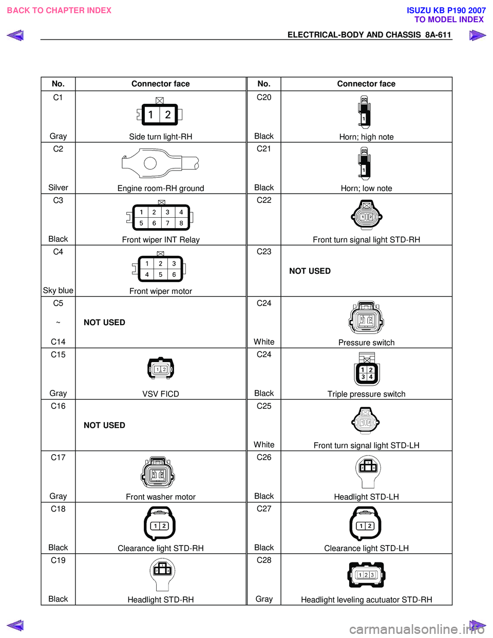
No. Connector face No. Connector face
C1
Gray
Side turn light-RH C20
BlackHorn; high note
C2
Silver
Engine room-RH ground C21
BlackHorn; low note
C3
Black
Front wiper INT Relay C22
Front turn signal light STD-RH
C4
Sky blue
Front wiper motor C23
NOT USED
C5
~
C14 NOT USED C24
White
Pressure switch
C15
Gray
VSV FICD C24
BlackTriple pressure switch
C16
NOT USED C25
White
Front turn signal light STD-LH
C17
Gray
Front washer motor C26
BlackHeadlight STD-LH
C18
Black
Clearance light STD-RH C27
BlackClearance light STD-LH
C19
Black
Headlight STD-RH C28
Gray Headlight leveling acutuator STD-RH
BACK TO CHAPTER INDEX TO MODEL INDEXISUZU KB P190 2007
Page 5553 of 6020
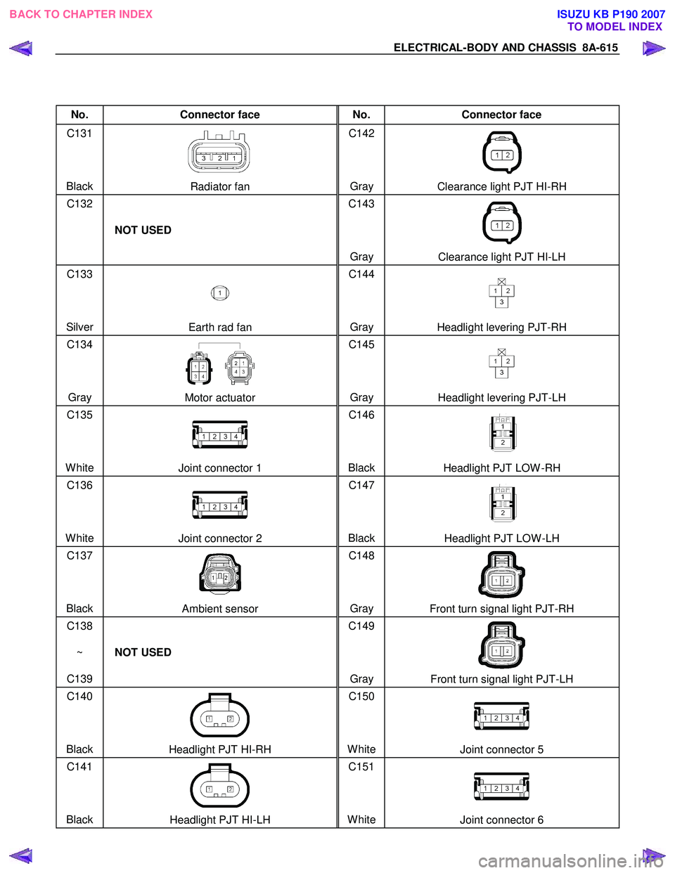
ELECTRICAL-BODY AND CHASSIS 8A-615
No. Connector face No. Connector face
C131
Black
Radiator fan C142
Gray Clearance light PJT HI-RH
C132
NOT USED C143
Gray
Clearance light PJT HI-LH
C133
Silver
Earth rad fan C144
Gray Headlight levering PJT-RH
C134
Gray
Motor actuator C145
Gray Headlight levering PJT-LH
C135
White
Joint connector 1 C146
BlackHeadlight PJT LOW -RH
C136
White
Joint connector 2 C147
BlackHeadlight PJT LOW -LH
C137
Black
Ambient sensor C148
Gray Front turn signal light PJT-RH
C138
~
C139 NOT USED C149
Gray
Front turn signal light PJT-LH
C140
Black
Headlight PJT HI-RH C150
WhiteJoint connector 5
C141
Black
Headlight PJT HI-LH C151
WhiteJoint connector 6
BACK TO CHAPTER INDEX TO MODEL INDEXISUZU KB P190 2007
Page 5556 of 6020
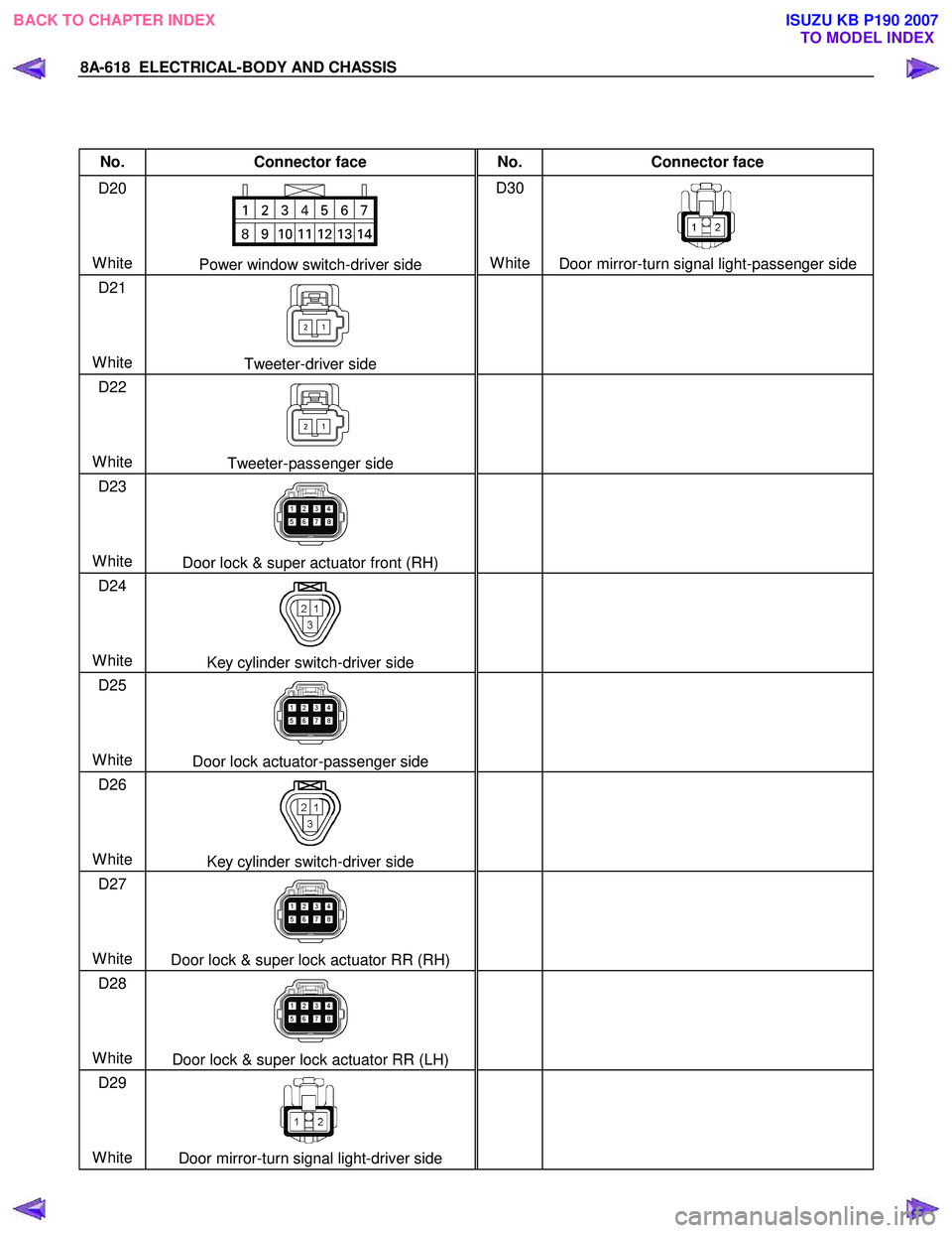
8A-618 ELECTRICAL-BODY AND CHASSIS
No. Connector face No. Connector face
D20
White
Power window switch-driver side D30
White
Door mirror-turn signal light-passenger side
D21
White
Tweeter-driver side
D22
White
Tweeter-passenger side
D23
White
Door lock & super actuator front (RH)
D24
White
Key cylinder switch-driver side
D25
White
Door lock actuator-passenger side
D26
White
Key cylinder switch-driver side
D27
White
Door lock & super lock actuator RR (RH)
D28
White
Door lock & super lock actuator RR (LH)
D29
White
Door mirror-turn signal light-driver side
BACK TO CHAPTER INDEX
TO MODEL INDEXISUZU KB P190 2007
Page 5574 of 6020
8B-2 CRUISE CONTROL SYSTEM
General Description
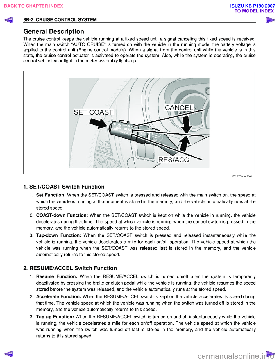
The cruise control keeps the vehicle running at a fixed speed until a signal canceling this fixed speed is received.
W hen the main switch “AUTO CRUISE” is turned on with the vehicle in the running mode, the battery voltage is
applied to the control unit (Engine control module). W hen a signal from the control unit while the vehicle is in this
state, the cruise control actuator is activated to operate the system. Also, while the system is operating, the cruise
control set indicator light in the meter assembly lights up.
RTU7Z0SH019601
1. SET/COAST Switch Function
1. Set Function: W hen the SET/COAST switch is pressed and released with the main switch on, the speed at
which the vehicle is running at that moment is stored in the memory, and the vehicle automatically runs at the
stored speed.
2. COAST-down Function: W hen the SET/COAST switch is kept on while the vehicle in running, the vehicle
decelerates during that time. The speed at which vehicle is running when the control switch is pressed in the
memory, and the vehicle automatically returns to the stored speed.
3. Tap-down Function: W hen the SET/COAST switch is pressed and released instantaneously while the
vehicle is running, the vehicle decelerates a mile for each on/off operation. The vehicle speed at which the
vehicle was running when the SET/COAST was released last is stored in the memory, and the vehicle
automatically returns to this stored speed.
2. RESUME/ACCEL Switch Function
1. Resume Function: W hen the RESUME/ACCEL switch is turned on/off after the system is temporarily
deactivated by pressing the brake or clutch pedal while the vehicle is running, the vehicle resumes the speed
stored before the system was released, and the vehicle automatically runs at the stored speed.
2. Accelerate Function: W hen the RESUME/ACCEL switch is kept on the vehicle accelerates its speed during
that time. The vehicle speed at which the vehicle was running when the switch was turned off is stored in the
memory, and the vehicle automatically returns to this speed.
3. Tap-up Function: W hen the RESUME/ACCEL switch is turned on and off instantaneously while the vehicle
is running, the vehicle decelerates a mile for each on/off operation. The vehicle speed at which the vehicle
was running when the switch was turned off last is stored in the memory, and the vehicle automatically
returns to this stored speed.
BACK TO CHAPTER INDEX TO MODEL INDEXISUZU KB P190 2007
Page 5584 of 6020
Cruise Control – HFV6 Page 8C–6
The stop lamp switch contacts are normally open with the brake pedal at rest and close when the brake pedal is pressed
turning on the vehicles brake lamps. These switch contacts also double as the cruise cancel signal for the cruise control
operation.
The cruise control initial brake apply signal function switch contacts are normally closed with the brake pedal at rest and
open when the brake pedal is pressed. This switch function is a safety requirement of the vehicle as it ensures that the
cruise control cannot be activated without the brake pedal first being pressed.
Powertrain Interface Module
The Powertrain Interface Module (PIM) is located on the driver’s side, kick trim panel. The purpose of the PIM is to act as
an interface between the drivetrain serial data bus (GMLAN protocol) and the body side data bus (UART Bus protocol).
All inputs from the cruise control switch assembly are directly wired to the PIM. The PIM then takes these inputs,
converts them to GMLAN protocol and sends the messages via the data bus to the engine control module (ECM). The
PIM also receives signals for the cruise control system from the ECM. When the ECM activates cruise control, it sends a
signal through the PIM (which converts it from GMLAN to UART protocol) to display the various cruise control messages
on the instrument cluster assembly.
For further information on the operation of the PIM, refer to 6E1 Powertrain Interface Module – V6.
Engine Control Module
The Engine Control Module (ECM) is mounted on the front of the engine. The role of the ECM is to receive all the inputs
from various sensors (vehicle speed (VSS) etc.) and switches to manage the engine. W hen a request is sent from the
cruise control switch assembly via the PIM to the ECM, the ECM will activate cruise control providing given parameters
are satisfied. Once the cruise is set, the ECM monitors the vehicle speed and controls the throttle actuator assembly thus
controlling the speed of the vehicle.
For further information on the operation of the ECM, refer to 6C1-1 Engine Management – V6 – General Information.
Throttle Actuator Control (TAC) Assembly
The throttle actuator control assembly is located on the front of the inlet manifold. The throttle actuator control assembly
receives signals from the ECM and controls the angle of the throttle plate. Refer to 6C1-1 Engine Management – V6 –
General Information for further information.
1.3 System Operation
Preliminary Information
Enabled and Disabled
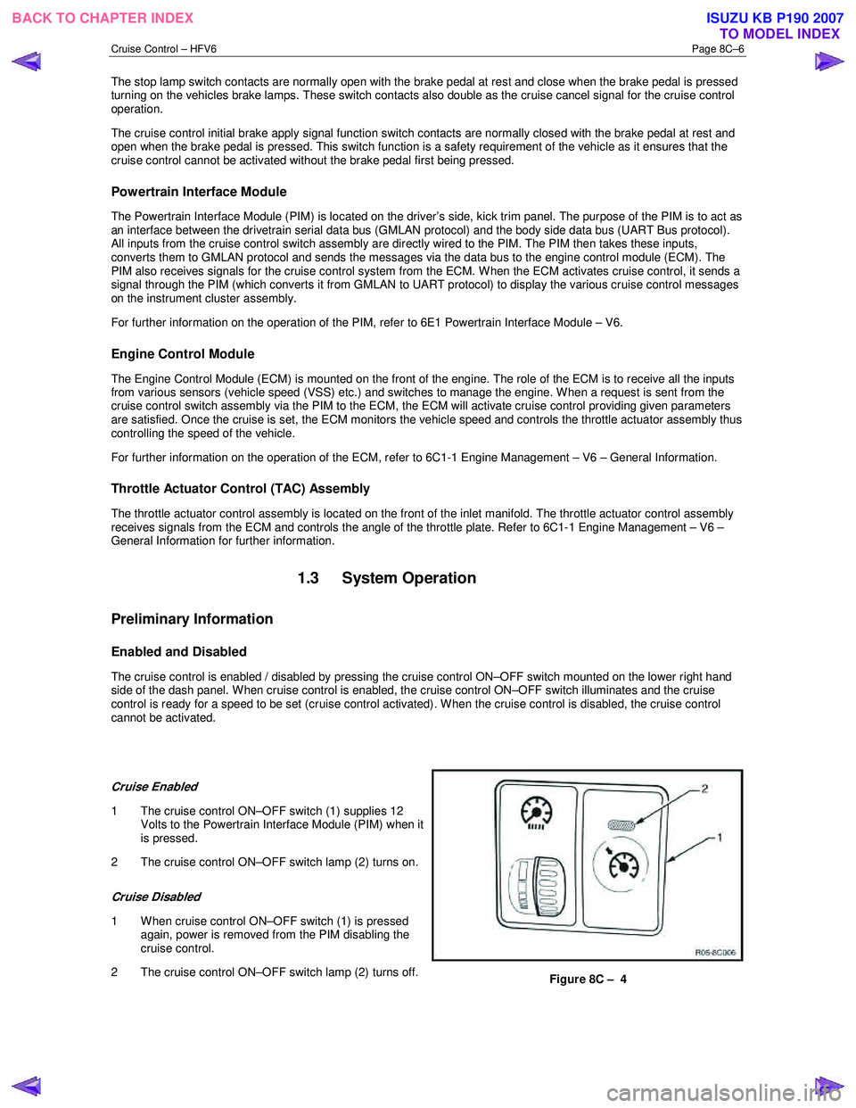
The cruise control is enabled / disabled by pressing the cruise control ON–OFF switch mounted on the lower right hand
side of the dash panel. When cruise control is enabled, the cruise control ON–OFF switch illuminates and the cruise
control is ready for a speed to be set (cruise control activated). W hen the cruise control is disabled, the cruise control
cannot be activated.
Cruise Enabled
1 The cruise control ON–OFF switch (1) supplies 12 Volts to the Powertrain Interface Module (PIM) when it
is pressed.
2 The cruise control ON–OFF switch lamp (2) turns on.
Cruise Disabled
1 W hen cruise control ON–OFF switch (1) is pressed again, power is removed from the PIM disabling the
cruise control.
2 The cruise control ON–OFF switch lamp (2) turns off.
Figure 8C – 4
BACK TO CHAPTER INDEX TO MODEL INDEXISUZU KB P190 2007