2007 ISUZU KB P190 turn signal
[x] Cancel search: turn signalPage 4439 of 6020
TRANSMISSION CONTROL SYSTEM (JR405E) 7A2-155
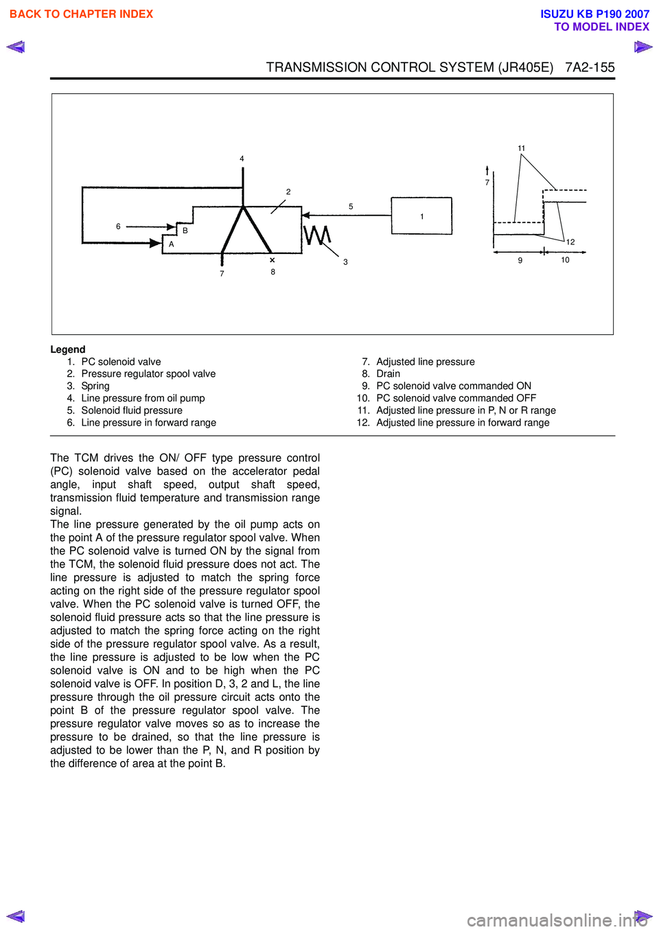
Legend1. PC solenoid valve
2. Pressure regulator spool valve
3. Spring
4. Line pressure from oil pump
5. Solenoid fluid pressure
6. Line pressure in forward range 7. Adjusted line pressure
8. Drain
9. PC solenoid valve commanded ON
10. PC solenoid valve commanded OFF 11. Adjusted line pressure in P, N or R range
12. Adjusted line pressure in forward range
The TCM drives the ON/ OFF type pressure control
(PC) solenoid valve based on the accelerator pedal
angle, input shaft speed, output shaft speed,
transmission fluid temperature and transmission range
signal.
The line pressure generated by the oil pump acts on
the point A of the pressure regulator spool valve. When
the PC solenoid valve is turned ON by the signal from
the TCM, the solenoid fluid pressure does not act. The
line pressure is adjusted to match the spring force
acting on the right side of the pressure regulator spool
valve. When the PC solenoid valve is turned OFF, the
solenoid fluid pressure acts so that the line pressure is
adjusted to match the spring force acting on the right
side of the pressure regulator spool valve. As a result,
the line pressure is adjusted to be low when the PC
solenoid valve is ON and to be high when the PC
solenoid valve is OFF. In position D, 3, 2 and L, the line
pressure through the oil pressure circuit acts onto the
point B of the pressure regulator spool valve. The
pressure regulator valve moves so as to increase the
pressure to be drained, so that the line pressure is
adjusted to be lower than the P, N, and R position by
the difference of area at the point B.
11
7
12
4
6 B
A 2
7 8 3 1
5
910
BACK TO CHAPTER INDEX
TO MODEL INDEX
ISUZU KB P190 2007
Page 4940 of 6020
8A-2 ELECTRICAL-BODY AND CHASSIS
PAGE
Fuse Block Circuit (4JJ1-TC/4JK1-TC (RHD)) SOUTH AFRICA ...............................8A- 39
Fuse Block Circuit (4JJ1-TC/4JK1-TC (RHD)) EXCEPT SOUTH AFRICA ...............8A- 41
Fuse Block Circuit (4JJ1-TC/4JK1-TC) - (LHD) G.EXP .............................................8A- 43
Fuse Block Circuit (4JH1-TC) - (LHD) ........................................................................8A- 45
Fuse Block Circuit (4JA1T (L)) ...................................................................................8A- 47
Grounding Point ..............................................................................................................8 A- 49
Ground Point ...............................................................................................................8A- 49
Ground Point Location ...............................................................................................8A- 89
Cable Harness Routing ...................................................................................................8A- 91
Main Cable Harness (RHD)..........................................................................................8A- 91
Instrument Harness (RHD) ..........................................................................................8A- 92
Main Cable Harness (LHD) ..........................................................................................8A- 93
Instrument Harness (LHD) ..........................................................................................8A- 94
Engine Harness C24SE ...............................................................................................8A- 95
Engine Harness 4JJ1-TC/4JK1-TC ............................................................................8A- 96
Engine Harness 4JH1-TC/4JA1T (L) ...........................................................................8A- 97
Transmission Harness ...............................................................................................8A- 98
System Repair ................................................................................................................. .8A- 100
Start and Charging ......................................................................................................8A- 10 0
Engine Control Module (ECM) ...................................................................................8A- 111
Exhaust Gas Recirculation (EGR) & GLOW; 4JA1T (L) Only ...................................8A- 143
Lighting ...................................................................................................................... ..8A- 149
Front Fog Light ...........................................................................................................8A- 180
Rear Fog Light ............................................................................................................8A- 190
Headlight Leveling ......................................................................................................8A- 19 4
Illumination .................................................................................................................. 8A- 200
Hazard Warning Flasher, Turn Signal Light, Backup Light, Horn and Stoplight ....................................................................................................8A- 213
Dome Light, Spotlight, Map Light and Warning Buzzer ..........................................8A- 245
Windshield Wiper and Washer ..................................................................................8A- 264
Transmission Control Module (TCM) ........................................................................8A- 285
Manual Transmission Shift Assist .............................................................................8A- 298
Meter, Warning Light and Indicator Light .................................................................8A- 303
Heater and Air Conditioning ......................................................................................8A- 371
Power Door Lock ........................................................................................................8A- 386
BACK TO CHAPTER INDEX
TO MODEL INDEX
ISUZU KB P190 2007
Page 4962 of 6020
8A-24 ELECTRICAL-BODY AND CHASSIS
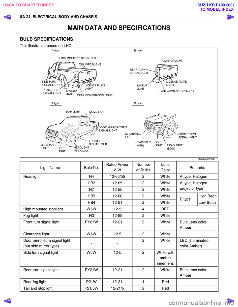
MAIN DATA AND SPECIFICATIONS
BULB SPECIFICATIONS
This illustration based on LHD
RTW 78AMF000801
Light Name Bulb No. Rated Power
V-W Number
of Bulbs Lens
Color Remarks
H4 12-60/55 2 W hite A type, Halogen
HB3 12-65 2 W hite
H7 12-55 2 W hite A type, Halogen
projector type
HB3 12-60 2 W hite High Bean
Headlight
HB4 12-51 2 W hite B type
Low Bean
High mounted stoplight W 5W 12-5 4 RED
Fog light H3 12-55 2 W hite
Front turn signal light PY21W 12-21 2 W hite Bulb Lens color
Amber
Clearance light W 5W 12-5 2 W hite
Door mirror-turn signal light
(out side mirror type) - -
2 W hite LED (Illuminated
color Amber)
Side turn signal light W 5W 12-5 2 W hite with
amber
inner lens
Rear turn signal light
PY21W 12-21 2 W hite Bulb Lens color
Amber
Rear fog light P21W 12-21 1 Red
Tail and stoplight P21/5W 12-21/5 2 Red
BACK TO CHAPTER INDEX
TO MODEL INDEXISUZU KB P190 2007
Page 4963 of 6020
ELECTRICAL-BODY AND CHASSIS 8A-25
Light Name Bulb No. Rated Power
V-W Number
of Bulbs Lens
Color Remarks
P16W 12-21 2 W hite Regular cab Backup light
P21W 12-16 2 W hite Extend cab, Crew cab
License plate light W 5W 12-5 2 W hite
A/C-Heater control light - 12-0.7 1 -
Dome light - 12-10 1 W hite
Spotlight/ Map light - 12-5 2 W hite
Light Name Rated Power
V-W Luminous Color Remarks
ILLUMINATION
LIGHT LED W hite
MULTI FUNCTION DISPLAY LCD Light blue
TURN SIGNAL LED Green
HIGH BEAM LED Blue
LOW FUEL LED Amber
A/T OIL TEMP LED Red
BRAKE LED Red
4W D LED Green
SEAT BELT LED Red
CHECK ENGINE LED Amber
OIL LED Red
FUEL FILTER LED Green
ABS LED Amber
SEDIMENTER LED Red
SRS LED Red
CHARGE LED Red
CHECK TRANS LED Red
CHECK 4W D LED Red
POW ER DRIVE LED Amber
3RD START LED Green
4W D-LOW LED Green
DOOR AJAR LED Red
P LED/LCD Green
R LED/LCD Green
N LED/LCD Green
D LED/LCD Green
3 LED/LCD Green
2 LED/LCD Green
A/T shift
indicator
L LED/LCD Green LED: Indicated on
the gauge
panel
LCD: Indicated on the
tachometer
panel
Meter
Illumination
light,
Indicator
light,
W arning
light
BACK TO CHAPTER INDEX TO MODEL INDEXISUZU KB P190 2007
Page 5104 of 6020
8A-166 ELECTRICAL-BODY AND CHASSIS
LIGHTING SYSTEM
REMOVAL AND INSTALLATION
3 2
1
RTW 78ASH000101
FRONT COMBINATION LIGHT (A type)
Removal
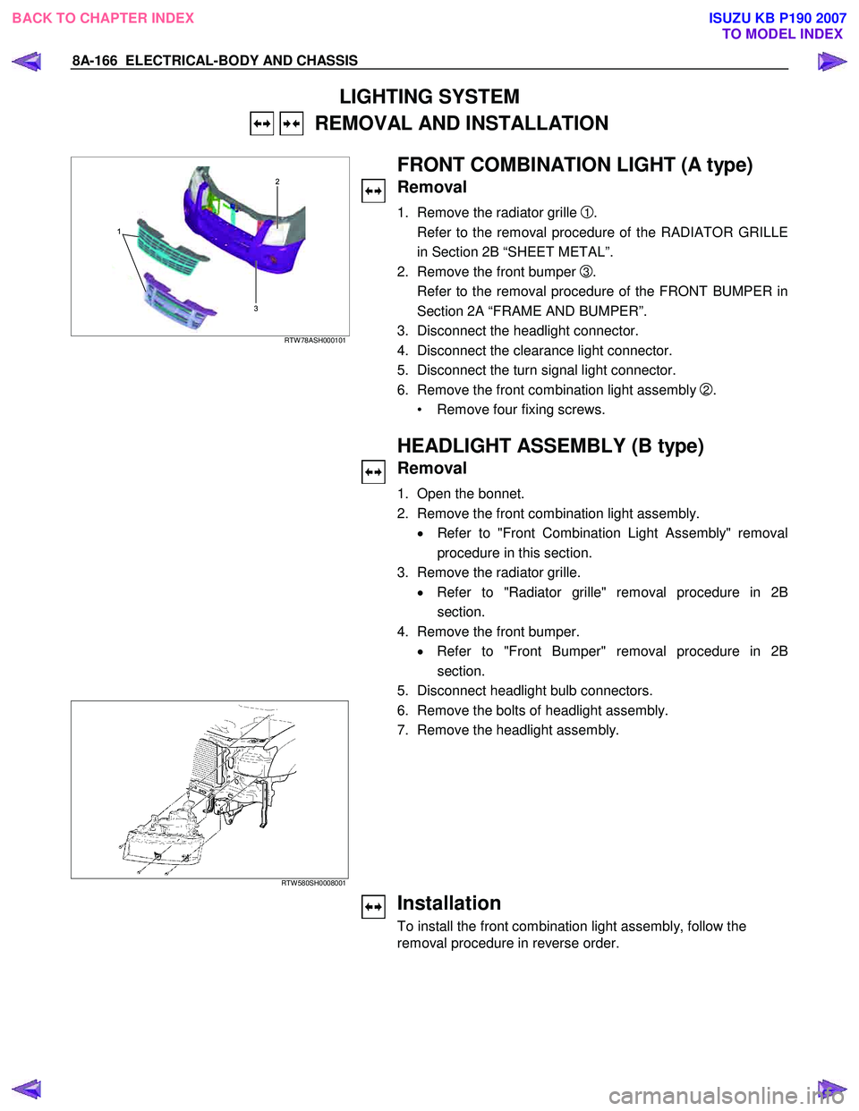
1. Remove the radiator grille 1.
Refer to the removal procedure of the RADIATOR GRILLE
in Section 2B “SHEET METAL”.
2. Remove the front bumper
3.
Refer to the removal procedure of the FRONT BUMPER in
Section 2A “FRAME AND BUMPER”.
3. Disconnect the headlight connector.
4. Disconnect the clearance light connector.
5. Disconnect the turn signal light connector.
6. Remove the front combination light assembly
2.
• Remove four fixing screws.
HEADLIGHT ASSEMBLY (B type)
Removal
1. Open the bonnet.
2. Remove the front combination light assembly. • Refer to "Front Combination Light Assembly" removal
procedure in this section.
3. Remove the radiator grille. • Refer to "Radiator grille" removal procedure in 2B
section.
4. Remove the front bumper. • Refer to "Front Bumper" removal procedure in 2B
section.
5. Disconnect headlight bulb connectors.
RTW 580SH0008001
6. Remove the bolts of headlight assembly. 7. Remove the headlight assembly.
Installation
To install the front combination light assembly, follow the
removal procedure in reverse order.
BACK TO CHAPTER INDEX TO MODEL INDEXISUZU KB P190 2007
Page 5108 of 6020
8A-170 ELECTRICAL-BODY AND CHASSIS
FRONT TURN SIGNAL LIGHT BULB
(A type)
Removal
HALOGEN STD TYPE RTW 78ASH000201
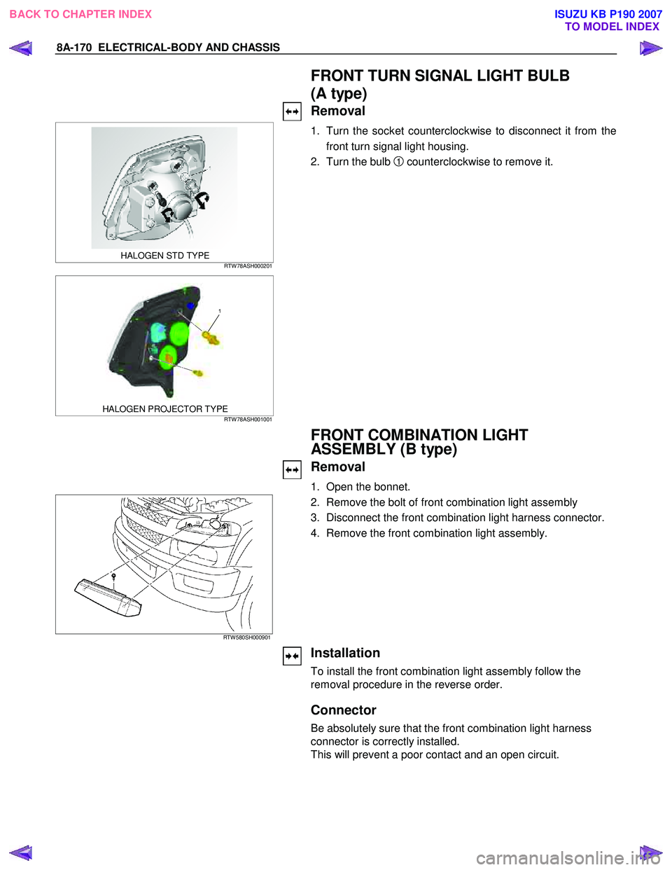
1. Turn the socket counterclockwise to disconnect it from the
front turn signal light housing.
2. Turn the bulb
1 counterclockwise to remove it.
1
HALOGEN PROJECTOR TYPE RTW 78ASH001001
FRONT COMBINATION LIGHT
ASSEMBLY (B type)
Removal
1. Open the bonnet.
RTW 580SH000901
2. Remove the bolt of front combination light assembly
3. Disconnect the front combination light harness connector.
4. Remove the front combination light assembly.
Installation
To install the front combination light assembly follow the
removal procedure in the reverse order.
Connector
Be absolutely sure that the front combination light harness
connector is correctly installed.
This will prevent a poor contact and an open circuit.
BACK TO CHAPTER INDEX TO MODEL INDEXISUZU KB P190 2007
Page 5109 of 6020
ELECTRICAL-BODY AND CHASSIS 8A-171
FRONT TURN SIGNAL LIGHT BULB
Removal
RTW 580SH000201
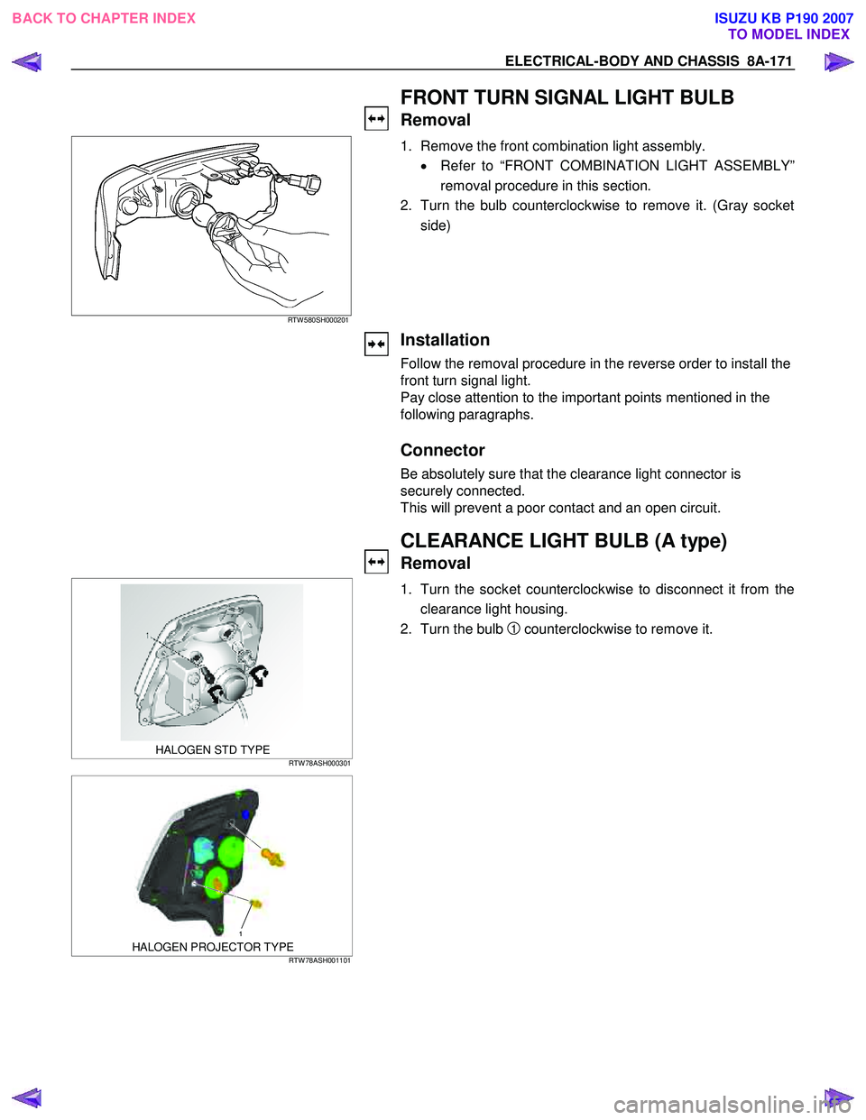
1. Remove the front combination light assembly.
• Refer to “FRONT COMBINATION LIGHT ASSEMBLY”
removal procedure in this section.
2. Turn the bulb counterclockwise to remove it. (Gray socket side)
Installation
Follow the removal procedure in the reverse order to install the
front turn signal light.
Pay close attention to the important points mentioned in the
following paragraphs.
Connector
Be absolutely sure that the clearance light connector is
securely connected.
This will prevent a poor contact and an open circuit.
CLEARANCE LIGHT BULB (A type)
Removal
HALOGEN STD TYPE RTW 78ASH000301
1. Turn the socket counterclockwise to disconnect it from the
clearance light housing.
2. Turn the bulb
1 counterclockwise to remove it.
1 HALOGEN PROJECTOR TYPE RTW 78ASH001101
BACK TO CHAPTER INDEX
TO MODEL INDEXISUZU KB P190 2007
Page 5151 of 6020
ELECTRICAL-BODY AND CHASSIS 8A-213
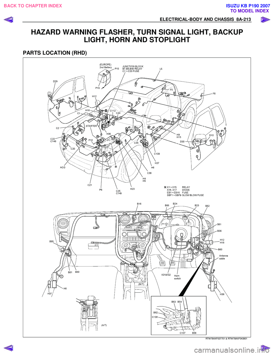
HAZARD WARNING FLASHER, TURN SIGNAL LIGHT, BACKUP LIGHT, HORN AND STOPLIGHT
PARTS LOCATION (RHD)
RTW 78AXF037701 & RTW 78AXF043901
BACK TO CHAPTER INDEX
TO MODEL INDEXISUZU KB P190 2007