2007 ISUZU KB P190 automatic transmission
[x] Cancel search: automatic transmissionPage 4091 of 6020
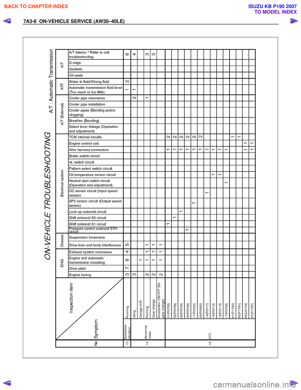
7A3-6 ON-VEHICLE SERVICE (AW30–40LE)
A/T : Automatic Transmission
BACK TO CHAPTER INDEX
TO MODEL INDEX
ISUZU KB P190 2007
Page 4134 of 6020
ON-VEHICLE SERVICE (AW30–40LE) 7A3-49
Major Components
Disassembly, inspection and reassembly of each
component group is indicated in the following chapter.
Before reassembly, make sure, again, that all
component groups are assembled correctly.
If something wrong is found in a certain component
group during assembly, inspect and repair this group
immediately.
General Assembly Notes:
1. The automatic transmission is composed of highly
precision-finished parts, necessitating careful
inspection before assembly because even a small
nick could cause fluid leakage or affect
performance.
2. Before assembling new clutch discs and brake
bands, soak them in automatic transmission fluid fo
r
at least thirty minutes.
3. Apply automatic transmission fluid on the sliding o
r
rotating surfaces of parts before assembly.
4. Use petroleum jelly to keep small parts in thei
r
palces.
5. Do not use adhesive cements on gaskets and similar parts.
6. W hen assembling the transmission, be sure to use new gaskets and O-rings.
7. Dry all parts with compressed air - never use shop rags.
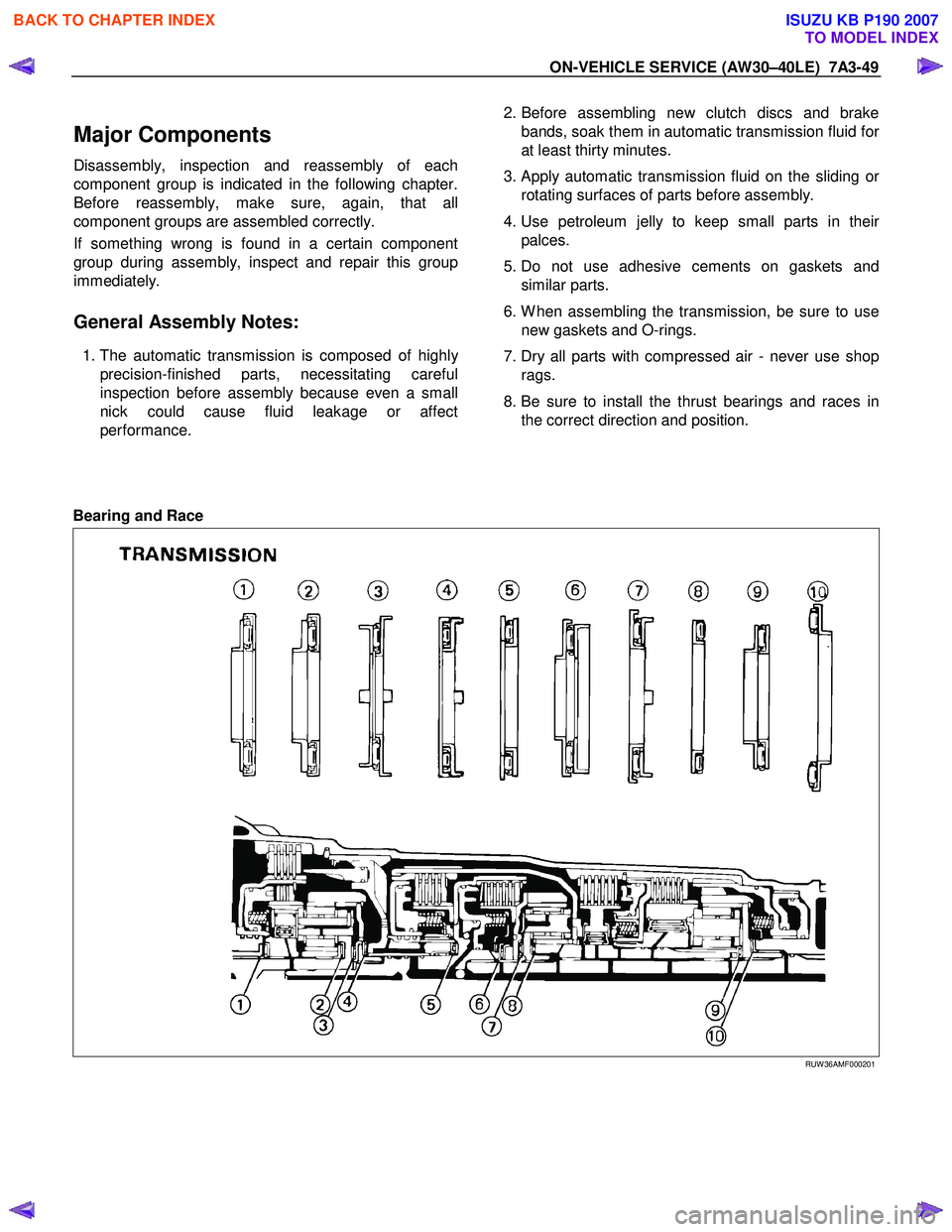
8. Be sure to install the thrust bearings and races in the correct direction and position.
Bearing and Race
RUW 36AMF000201
BACK TO CHAPTER INDEX
TO MODEL INDEX
ISUZU KB P190 2007
Page 4171 of 6020
7A4–36 UNIT REPAIR (AW30–40LE)
Diaassembly, Inspection and
Reassembly of minor Components
NOTE: The instructions here are organized so that you
work on only one component group at a time.
This will help avoid confusion from similar-looking parts
of different subassemblies being on your workbench at
the same time.
The component groups are inspected and repaired from
the converter housing side.
As much as possible, complete the inspection, repair
and reassembly before proceeding to the next
component group. If a component group cannot be
reassembled because parts are being ordered, be sure
to keep all parts of that group in separate container
while proceeding with disassembly, inspection, repair
and reassembly of other component groups.
Recommended ATF type DEXRON III.
General Cleaning Notes:
1. All disassembled parts should be washed clean and any fluid passages and holes should be blown
through with compressed air.
2. When using compressed air to dry parts, always aim away from yourself to prevent accidentally spraying
automatic transmission fluid in your face.
3. The recommended automatic transmission fluid should be used for cleaning.
Parts Arrangement:
1. After cleaning, the parts should be arranged inproper order to allow performing inspection, repairs,
and reassembly with efficiency.
2. When disassembling a valve body, be sure to keep each valve together with the corresponding spring.
3. New brakes and clutches that are to be used for replacement must be soaked in transmission fluid
for at least thirty minutes before assembly.
General Assembly:
1. All oil seal rings, clutch discs, clutch plates, rotating parts, and sliding surfaces should be coated with
transmission fluid prior to reassembly.
2. All gaskets and rubber O-ring should be replaced.
3. Make sure that the ends of a snap ring are not aligned with one of the cutouts and are installed in
the groove correctly.
4. If a worn bushing is to be replaced, the subassembly containing that bushing must be
replaced.
5. Check thrust bearings and races for wear or damage. Replace if necessary.
6. Use petroleum jelly or vaseline to keep parts in place.
BACK TO CHAPTER INDEX
TO MODEL INDEX
ISUZU KB P190 2007
Page 4242 of 6020
CONSTRUCTION AND FUNCTION 7A1-3
DESCRIPTION
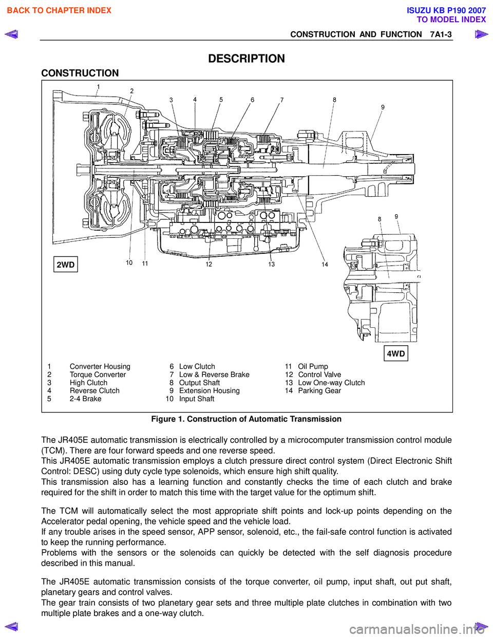
CONSTRUCTION
1 Converter Housing 6 Low Clutch 11 Oil Pump
2 Torque Converter 7 Low & Reverse Brake 12 Control Valve
3 High Clutch 8 Output Shaft 13 Low One-way Clutch
4 Reverse Clutch 9 Extension Housing 14 Parking Gear
5 2-4 Brake 10 Input Shaft
Figure 1. Construction of Automatic Transmission
The JR405E automatic transmission is electrically controlled by a microcomputer transmission control module
(TCM). There are four forward speeds and one reverse speed.
This JR405E automatic transmission employs a clutch pressure direct control system (Direct Electronic Shift
Control: DESC) using duty cycle type solenoids, which ensure high shift quality.
This transmission also has a learning function and constantly checks the time of each clutch and brake
required for the shift in order to match this time with the target value for the optimum shift.
The TCM will automatically select the most appropriate shift points and lock-up points depending on the
Accelerator pedal opening, the vehicle speed and the vehicle load.
If any trouble arises in the speed sensor, APP sensor, solenoid, etc., the fail-safe control function is activated
to keep the running performance.
Problems with the sensors or the solenoids can quickly be detected with the self diagnosis procedure
described in this manual.
The JR405E automatic transmission consists of the torque converter, oil pump, input shaft, out put shaft,
planetary gears and control valves.
The gear train consists of two planetary gear sets and three multiple plate clutches in combination with two
multiple plate brakes and a one-way clutch.
2WD
4WD
BACK TO CHAPTER INDEX
TO MODEL INDEX
ISUZU KB P190 2007
Page 4265 of 6020
7A1-26 CONSTRUCTION AND FUNCTION
CONTROL MECHANISM
CONTENT OF FUNCTION AND CONTROL
Item Description
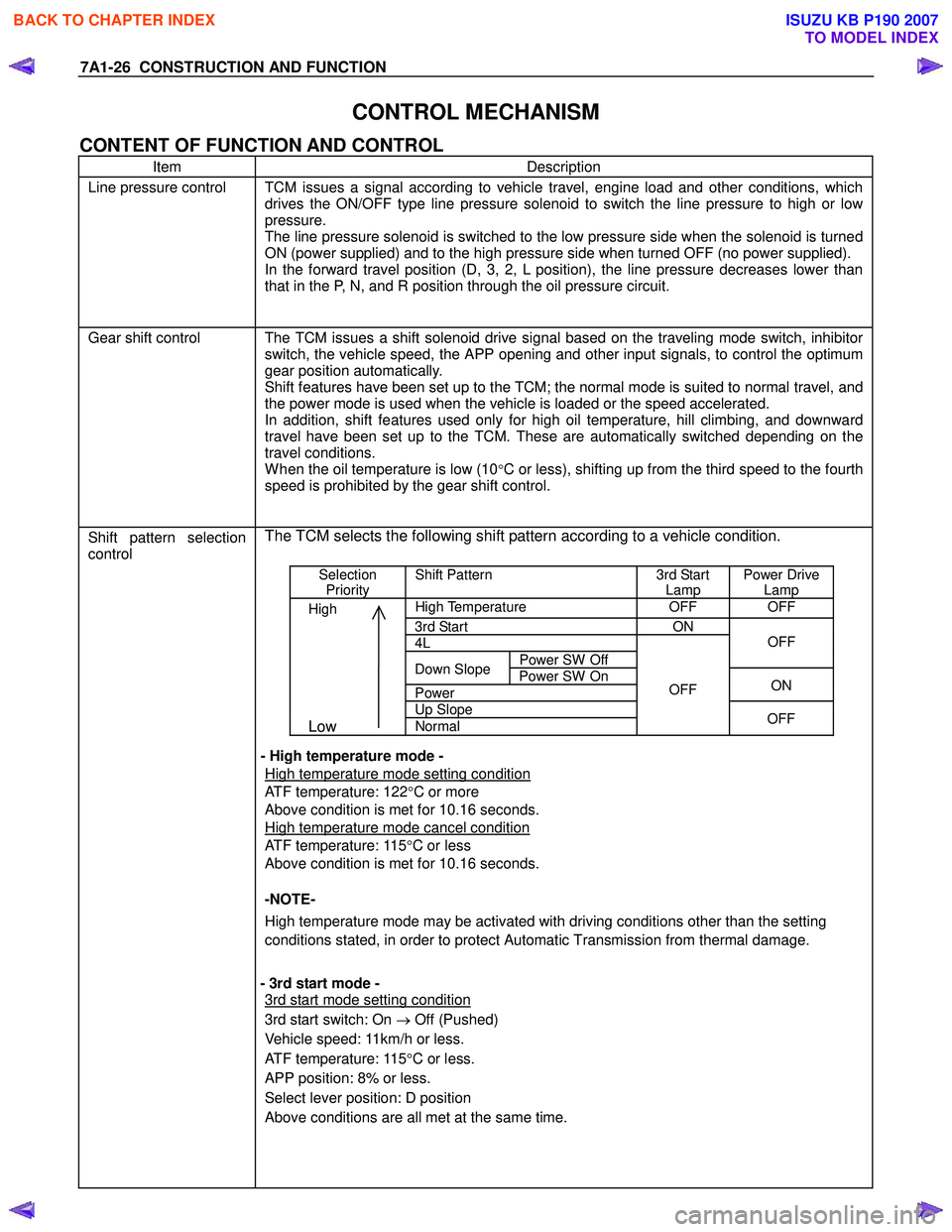
Line pressure control TCM issues a signal according to vehicle travel, engine load and other conditions, which
drives the ON/OFF type line pressure solenoid to switch the line pressure to high or low
pressure.
The line pressure solenoid is switched to the low pressure side when the solenoid is turned
ON (power supplied) and to the high pressure side when turned OFF (no power supplied).
In the forward travel position (D, 3, 2, L position), the line pressure decreases lower than
that in the P, N, and R position through the oil pressure circuit.
Gear shift control The TCM issues a shift solenoid drive signal based on the traveling mode switch, inhibitor
switch, the vehicle speed, the APP opening and other input signals, to control the optimum
gear position automatically.
Shift features have been set up to the TCM; the normal mode is suited to normal travel, and
the power mode is used when the vehicle is loaded or the speed accelerated.
In addition, shift features used only for high oil temperature, hill climbing, and downward
travel have been set up to the TCM. These are automatically switched depending on the
travel conditions.
W hen the oil temperature is low (10°C or less), shifting up from the third speed to the fourth
speed is prohibited by the gear shift control.
Shift pattern selection
control
The TCM selects the following shift pattern according to a vehicle condition.
Selection
Priority Shift Pattern 3rd Start
Lamp Power Drive
Lamp
High High Temperature OFF OFF
3rd Start ON
4L
Power SW Off
OFF
Down Slope
Power SW On
Power ON
Up Slope
Low Normal
OFF
OFF
- High temperature mode -
High temperature mode setting condition
ATF temperature: 122 °C or more
Above condition is met for 10.16 seconds.
High temperature mode cancel condition
ATF temperature: 115 °C or less
Above condition is met for 10.16 seconds.
-NOTE-
High temperature mode may be activated with driving conditions other than the setting
conditions stated, in order to protect Automatic Transmission from thermal damage.
- 3rd start mode -
3rd start mode setting condition
3rd start switch: On → Off (Pushed)
Vehicle speed: 11km/h or less.
ATF temperature: 115 °C or less.
APP position: 8% or less.
Select lever position: D position
Above conditions are all met at the same time.
BACK TO CHAPTER INDEX
TO MODEL INDEX
ISUZU KB P190 2007
Page 4267 of 6020
7A1-28 CONSTRUCTION AND FUNCTION
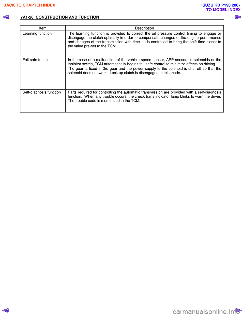
Item Description
Learning function The learning function is provided to correct the oil pressure control timing to engage or
disengage the clutch optimally in order to compensate changes of the engine performance
and changes of the transmission with time. It is controlled to bring the shift time closer to
the value pre-set to the TCM.
Fail-safe function In the case of a malfunction of the vehicle speed sensor, APP sensor, all solenoids or the
inhibitor switch, TCM automatically begins fail-safe control to minimize effects on driving.
The gear is fixed in 3rd gear and the power supply to the solenoid is shut off so that the
solenoid does not work. Lock up clutch is disengaged in this mode.
Self-diagnosis function Parts required for controlling the automatic transmission are provided with a self-diagnosis
function. W hen any trouble occurs, the check trans indicator lamp blinks to warn the driver.
The trouble code is memorized in the TCM.
BACK TO CHAPTER INDEX
TO MODEL INDEX
ISUZU KB P190 2007
Page 4308 of 6020
7A2-24 TRANSMISSION CONTROL SYSTEM (JR405E)
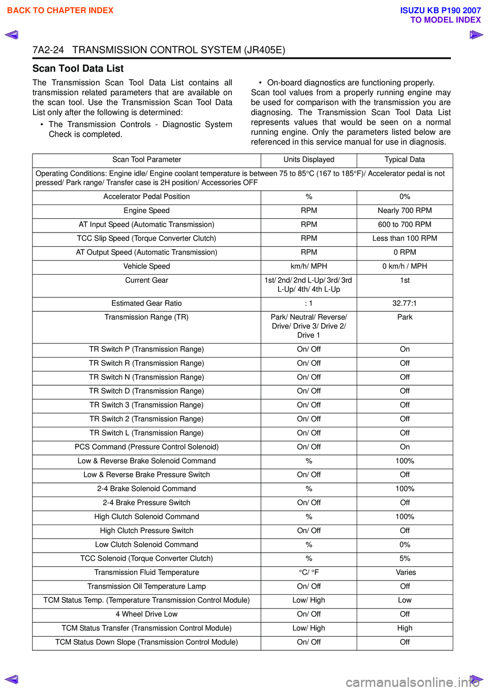
Scan Tool Data List
The Transmission Scan Tool Data List contains all
transmission related parameters that are available on
the scan tool. Use the Transmission Scan Tool Data
List only after the following is determined:
• The Transmission Controls - Diagnostic System Check is completed. • On-board diagnostics are functioning properly.
Scan tool values from a properly running engine may
be used for comparison with the transmission you are
diagnosing. The Transmission Scan Tool Data List
represents values that would be seen on a normal
running engine. Only the parameters listed below are
referenced in this service manual for use in diagnosis.
Scan Tool Parameter Units DisplayedTypical Data
Operating Conditions: Engine idle/ Engine coolant temperature is between 75 to 85 °C (167 to 185 °F)/ Accelerator pedal is not
pressed/ Park range/ Transfer case is 2H position/ Accessories OFF
Accelerator Pedal Position %0%
Engine Speed RPMNearly 700 RPM
AT Input Speed (Automatic Transmission) RPM600 to 700 RPM
TCC Slip Speed (Torque Converter Clutch) RPMLess than 100 RPM
AT Output Speed (Automatic Transmission) RPM0 RPM
Vehicle Speed km/h/ MPH0 km/h / MPH
Current Gear 1st/ 2nd/ 2nd L-Up/ 3rd/ 3rd
L-Up/ 4th/ 4th L-Up 1st
Estimated Gear Ratio : 132.77:1
Transmission Range (TR) Park/ Neutral/ Reverse/
Drive/ Drive 3/ Drive 2/ Drive 1 Park
TR Switch P (Transmission Range) On/ OffOn
TR Switch R (Transmission Range) On/ OffOff
TR Switch N (Transmission Range) On/ OffOff
TR Switch D (Transmission Range) On/ OffOff
TR Switch 3 (Transmission Range) On/ OffOff
TR Switch 2 (Transmission Range) On/ OffOff
TR Switch L (Transmission Range) On/ OffOff
PCS Command (Pressure Control Solenoid) On/ OffOn
Low & Reverse Brake Solenoid Command %100%
Low & Reverse Brake Pressure Switch On/ OffOff
2-4 Brake Solenoid Command %100%
2-4 Brake Pressure Switch On/ OffOff
High Clutch Solenoid Command %100%
High Clutch Pressure Switch On/ OffOff
Low Clutch Solenoid Command %0%
TCC Solenoid (Torque Converter Clutch) %5%
Transmission Fluid Temperature °C/ °F V arie s
Transmission Oil Temperature Lamp On/ OffOff
TCM Status Temp. (Temperature Transmission Control Module) Low/ HighLow
4 Wheel Drive Low On/ OffOff
TCM Status Transfer (Transmission Control Module) Low/ HighHigh
TCM Status Down Slope (Transmission Control Module) On/ OffOff
BACK TO CHAPTER INDEX
TO MODEL INDEX
ISUZU KB P190 2007
Page 4309 of 6020
TRANSMISSION CONTROL SYSTEM (JR405E) 7A2-25
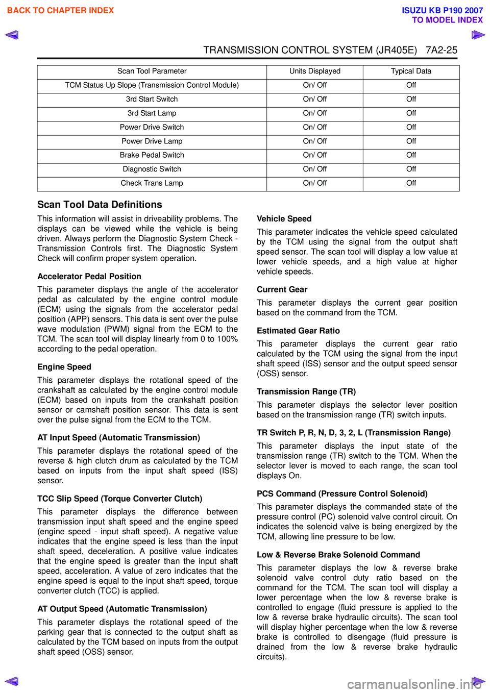
Scan Tool Data Definitions
This information will assist in driveability problems. The
displays can be viewed while the vehicle is being
driven. Always perform the Diagnostic System Check -
Transmission Controls first. The Diagnostic System
Check will confirm proper system operation.
Accelerator Pedal Position
This parameter displays the angle of the accelerator
pedal as calculated by the engine control module
(ECM) using the signals from the accelerator pedal
position (APP) sensors. This data is sent over the pulse
wave modulation (PWM) signal from the ECM to the
TCM. The scan tool will display linearly from 0 to 100%
according to the pedal operation.
Engine Speed
This parameter displays the rotational speed of the
crankshaft as calculated by the engine control module
(ECM) based on inputs from the crankshaft position
sensor or camshaft position sensor. This data is sent
over the pulse signal from the ECM to the TCM.
AT Input Speed (Automatic Transmission)
This parameter displays the rotational speed of the
reverse & high clutch drum as calculated by the TCM
based on inputs from the input shaft speed (ISS)
sensor.
TCC Slip Speed (Torque Converter Clutch)
This parameter displays the difference between
transmission input shaft speed and the engine speed
(engine speed - input shaft speed). A negative value
indicates that the engine speed is less than the input
shaft speed, deceleration. A positive value indicates
that the engine speed is greater than the input shaft
speed, acceleration. A value of zero indicates that the
engine speed is equal to the input shaft speed, torque
converter clutch (TCC) is applied.
AT Output Speed (Automatic Transmission)
This parameter displays the rotational speed of the
parking gear that is connected to the output shaft as
calculated by the TCM based on inputs from the output
shaft speed (OSS) sensor. Vehicle Speed
This parameter indicates the vehicle speed calculated
by the TCM using the signal from the output shaft
speed sensor. The scan tool will display a low value at
lower vehicle speeds, and a high value at higher
vehicle speeds.
Current Gear
This parameter displays the current gear position
based on the command from the TCM.
Estimated Gear Ratio
This parameter displays the current gear ratio
calculated by the TCM using the signal from the input
shaft speed (ISS) sensor and the output speed sensor
(OSS) sensor.
Transmission Range (TR)
This parameter displays the selector lever position
based on the transmission range (TR) switch inputs.
TR Switch P, R, N, D, 3, 2, L (Transmission Range)
This parameter displays the input state of the
transmission range (TR) switch to the TCM. When the
selector lever is moved to each range, the scan tool
displays On.
PCS Command (Pressure Control Solenoid)
This parameter displays the commanded state of the
pressure control (PC) solenoid valve control circuit. On
indicates the solenoid valve is being energized by the
TCM, allowing line pressure to be low.
Low & Reverse Brake Solenoid Command
This parameter displays the low & reverse brake
solenoid valve control duty ratio based on the
command for the TCM. The scan tool will display a
lower percentage when the low & reverse brake is
controlled to engage (fluid pressure is applied to the
low & reverse brake hydraulic circuits). The scan tool
will display higher percentage when the low & reverse
brake is controlled to disengage (fluid pressure is
drained from the low & reverse brake hydraulic
circuits).
TCM Status Up Slope (Transmission Control Module) On/ OffOff
3rd Start Switch On/ OffOff
3rd Start Lamp On/ OffOff
Power Drive Switch On/ OffOff
Power Drive Lamp On/ OffOff
Brake Pedal Switch On/ OffOff
Diagnostic Switch On/ OffOff
Check Trans Lamp On/ OffOff
Scan Tool Parameter
Units DisplayedTypical Data
BACK TO CHAPTER INDEX
TO MODEL INDEX
ISUZU KB P190 2007