Page 4058 of 6020
7A2-92 TRANSMISSION CONTROL SYSTEM (AW30–40LE)
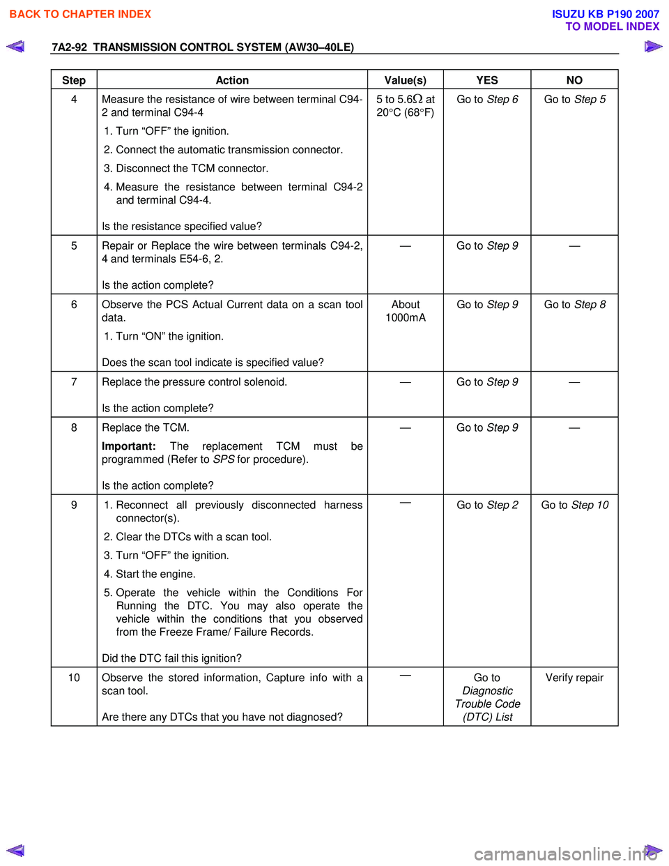
Step Action Value(s) YES NO
4 Measure the resistance of wire between terminal C94-
2 and terminal C94-4
1. Turn “OFF” the ignition.
2. Connect the automatic transmission connector.
3. Disconnect the TCM connector.
4. Measure the resistance between terminal C94-2
and terminal C94-4.
Is the resistance specified value? 5 to 5.6Ω at
20 °C (68 °F) Go to
Step 6 Go to Step 5
5 Repair or Replace the wire between terminals C94-2,
4 and terminals E54-6, 2.
Is the action complete? — Go to
Step 9 —
6 Observe the PCS Actual Current data on a scan tool
data.
1. Turn “ON” the ignition.
Does the scan tool indicate is specified value? About
1000mA Go to
Step 9 Go to Step 8
7 Replace the pressure control solenoid.
Is the action complete? — Go to
Step 9 —
8 Replace the TCM.
Important: The replacement TCM must be
programmed (Refer to SPS for procedure).
Is the action complete? — Go to
Step 9 —
9 1. Reconnect all previously disconnected harness
connector(s).
2. Clear the DTCs with a scan tool.
3. Turn “OFF” the ignition.
4. Start the engine.
5. Operate the vehicle within the Conditions For Running the DTC. You may also operate the
vehicle within the conditions that you observed
from the Freeze Frame/ Failure Records.
Did the DTC fail this ignition? —
Go to Step 2 Go to Step 10
10 Observe the stored information, Capture info with a
scan tool.
Are there any DTCs that you have not diagnosed? —
Go to
Diagnostic
Trouble Code (DTC) List Verify repair
BACK TO CHAPTER INDEX
TO MODEL INDEX
ISUZU KB P190 2007
Page 4061 of 6020
TRANSMISSION CONTROL SYSTEM (AW30–40LE) 7A2-95
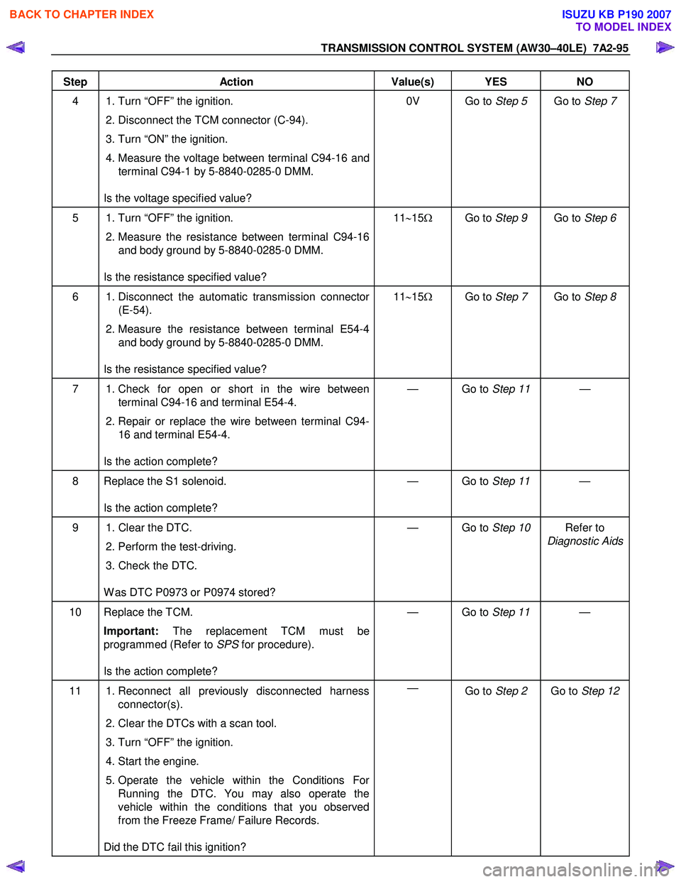
Step Action Value(s) YES NO
4 1. Turn “OFF” the ignition.
2. Disconnect the TCM connector (C-94).
3. Turn “ON” the ignition.
4. Measure the voltage between terminal C94-16 and terminal C94-1 by 5-8840-0285-0 DMM.
Is the voltage specified value? 0V Go to
Step 5 Go to Step 7
5 1. Turn “OFF” the ignition.
2. Measure the resistance between terminal C94-16
and body ground by 5-8840-0285-0 DMM.
Is the resistance specified value? 11
∼15 Ω Go to Step 9 Go to Step 6
6 1. Disconnect the automatic transmission connector
(E-54).
2. Measure the resistance between terminal E54-4
and body ground by 5-8840-0285-0 DMM.
Is the resistance specified value? 11
∼15 Ω Go to Step 7 Go to Step 8
7 1. Check for open or short in the wire between
terminal C94-16 and terminal E54-4.
2. Repair or replace the wire between terminal C94-
16 and terminal E54-4.
Is the action complete? — Go to
Step 11 —
8 Replace the S1 solenoid.
Is the action complete? — Go to
Step 11 —
9 1. Clear the DTC.
2. Perform the test-driving.
3. Check the DTC.
W as DTC P0973 or P0974 stored? — Go to
Step 10 Refer to
Diagnostic Aids
10 Replace the TCM.
Important: The replacement TCM must be
programmed (Refer to SPS for procedure).
Is the action complete? — Go to
Step 11 —
11 1. Reconnect all previously disconnected harness
connector(s).
2. Clear the DTCs with a scan tool.
3. Turn “OFF” the ignition.
4. Start the engine.
5. Operate the vehicle within the Conditions For Running the DTC. You may also operate the
vehicle within the conditions that you observed
from the Freeze Frame/ Failure Records.
Did the DTC fail this ignition? —
Go to Step 2 Go to Step 12
BACK TO CHAPTER INDEX
TO MODEL INDEX
ISUZU KB P190 2007
Page 4065 of 6020
TRANSMISSION CONTROL SYSTEM (AW30–40LE) 7A2-99
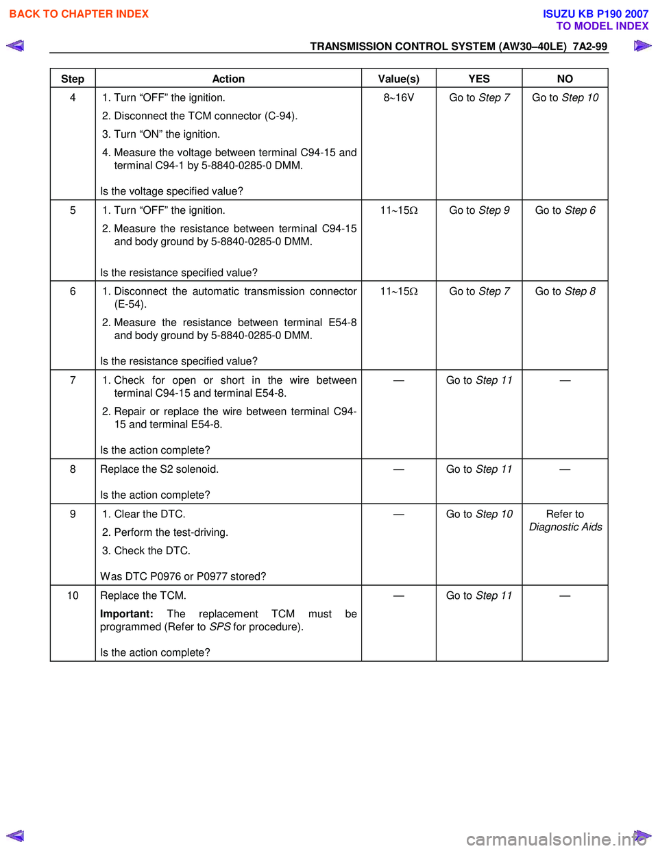
Step Action Value(s) YES NO
4 1. Turn “OFF” the ignition.
2. Disconnect the TCM connector (C-94).
3. Turn “ON” the ignition.
4. Measure the voltage between terminal C94-15 and
terminal C94-1 by 5-8840-0285-0 DMM.
Is the voltage specified value? 8
∼16V Go to Step 7 Go to Step 10
5 1. Turn “OFF” the ignition.
2. Measure the resistance between terminal C94-15
and body ground by 5-8840-0285-0 DMM.
Is the resistance specified value? 11
∼15 Ω Go to Step 9 Go to Step 6
6 1. Disconnect the automatic transmission connector
(E-54).
2. Measure the resistance between terminal E54-8
and body ground by 5-8840-0285-0 DMM.
Is the resistance specified value? 11
∼15 Ω Go to Step 7 Go to Step 8
7 1. Check for open or short in the wire between
terminal C94-15 and terminal E54-8.
2. Repair or replace the wire between terminal C94-
15 and terminal E54-8.
Is the action complete? — Go to
Step 11 —
8 Replace the S2 solenoid.
Is the action complete? — Go to
Step 11 —
9 1. Clear the DTC.
2. Perform the test-driving.
3. Check the DTC.
W as DTC P0976 or P0977 stored? — Go to
Step 10 Refer to
Diagnostic Aids
10 Replace the TCM.
Important: The replacement TCM must be
programmed (Refer to SPS for procedure).
Is the action complete? — Go to
Step 11 —
BACK TO CHAPTER INDEX
TO MODEL INDEX
ISUZU KB P190 2007
Page 4073 of 6020
TRANSMISSION CONTROL SYSTEM (AW30–40LE) 7A2-107
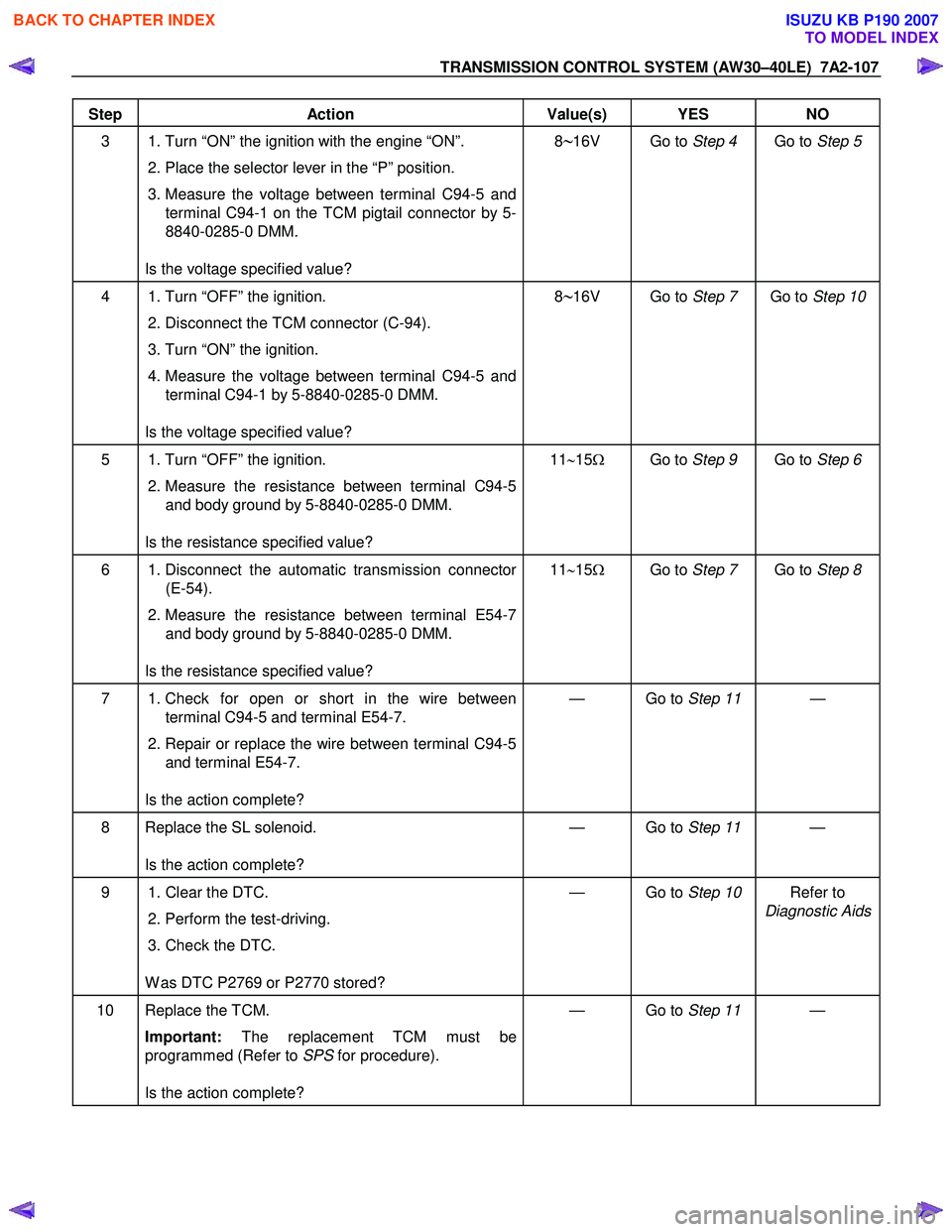
Step Action Value(s) YES NO
3 1. Turn “ON” the ignition with the engine “ON”.
2. Place the selector lever in the “P” position.
3. Measure the voltage between terminal C94-5 and terminal C94-1 on the TCM pigtail connector by 5-
8840-0285-0 DMM.
Is the voltage specified value? 8∼16V Go to
Step 4 Go to Step 5
4 1. Turn “OFF” the ignition.
2. Disconnect the TCM connector (C-94).
3. Turn “ON” the ignition.
4. Measure the voltage between terminal C94-5 and
terminal C94-1 by 5-8840-0285-0 DMM.
Is the voltage specified value? 8∼16V Go to
Step 7 Go to Step 10
5 1. Turn “OFF” the ignition.
2. Measure the resistance between terminal C94-5
and body ground by 5-8840-0285-0 DMM.
Is the resistance specified value? 11
∼15 Ω Go to Step 9 Go to Step 6
6 1. Disconnect the automatic transmission connector
(E-54).
2. Measure the resistance between terminal E54-7
and body ground by 5-8840-0285-0 DMM.
Is the resistance specified value? 11
∼15 Ω Go to Step 7 Go to Step 8
7 1. Check for open or short in the wire between
terminal C94-5 and terminal E54-7.
2. Repair or replace the wire between terminal C94-5
and terminal E54-7.
Is the action complete? — Go to
Step 11 —
8 Replace the SL solenoid.
Is the action complete? — Go to
Step 11 —
9 1. Clear the DTC.
2. Perform the test-driving.
3. Check the DTC.
W as DTC P2769 or P2770 stored? — Go to
Step 10 Refer to
Diagnostic Aids
10 Replace the TCM.
Important: The replacement TCM must be
programmed (Refer to SPS for procedure).
Is the action complete? — Go to
Step 11 —
BACK TO CHAPTER INDEX
TO MODEL INDEX
ISUZU KB P190 2007
Page 4078 of 6020
7A2-112 TRANSMISSION CONTROL SYSTEM (AW30–40LE)
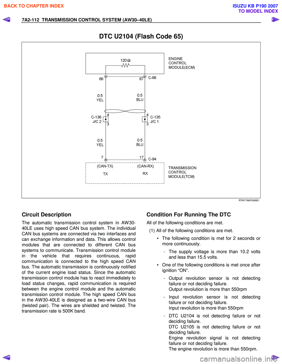
DTC U2104 (Flash Code 65)
RTW 77AMF000801
Circuit Description
The automatic transmission control system in AW 30-
40LE uses high speed CAN bus system. The individual
CAN bus systems are connected via two interfaces and
can exchange information and data. This allows control
modules that are connected to different CAN bus
systems to communicate. Transmission control module
in the vehicle that requires continuous, rapid
communication is connected to the high speed CAN
bus. The automatic transmission is continuously notified
of the current engine load status. Since the automatic
transmission control module has to react immediately to
load status changes, rapid communication is required
between the engine control module and the automatic
transmission control module. The high speed CAN bus
in the AW 30-40LE is designed as a two-wire CAN bus
(twisted pair). The wires are shielded and twisted. The
transmission rate is 500K band.
Condition For Running The DTC
All of the following conditions are met.
(1) All of the following conditions are met. • The following condition is met for 2 seconds o
r
more continuously.
- The supply voltage is more than 10.2 volts and less than 15.5 volts.
• One of the following conditions is met once afte
r
ignition “ON”.
- Output revolution sensor is not detecting failure or not deciding failure.
Output revolution is more than 550rpm
- Input revolution sensor is not detecting failure or not deciding failure.
Input revolution is more than 550rpm
- DTC U2104 is not detecting failure or not deciding failure.
DTC U2105 is not detecting failure or not
deciding failure.
Engine revolution signal is not detecting
failure or not deciding failure.
The engine revolution is more than 550rpm.
BACK TO CHAPTER INDEX
TO MODEL INDEX
ISUZU KB P190 2007
Page 4082 of 6020
7A2-116 TRANSMISSION CONTROL SYSTEM (AW30–40LE)
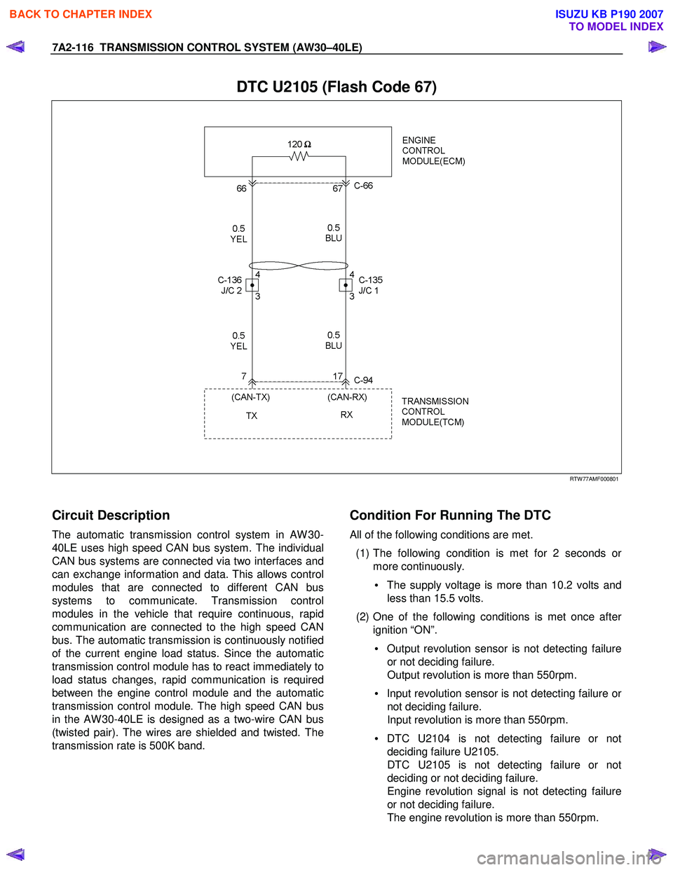
DTC U2105 (Flash Code 67)
RTW 77AMF000801
Circuit Description
The automatic transmission control system in AW 30-
40LE uses high speed CAN bus system. The individual
CAN bus systems are connected via two interfaces and
can exchange information and data. This allows control
modules that are connected to different CAN bus
systems to communicate. Transmission control
modules in the vehicle that require continuous, rapid
communication are connected to the high speed CAN
bus. The automatic transmission is continuously notified
of the current engine load status. Since the automatic
transmission control module has to react immediately to
load status changes, rapid communication is required
between the engine control module and the automatic
transmission control module. The high speed CAN bus
in the AW 30-40LE is designed as a two-wire CAN bus
(twisted pair). The wires are shielded and twisted. The
transmission rate is 500K band.
Condition For Running The DTC
All of the following conditions are met.
(1) The following condition is met for 2 seconds o
r
more continuously.
• The supply voltage is more than 10.2 volts and
less than 15.5 volts.
(2) One of the following conditions is met once afte
r
ignition “ON”.
• Output revolution sensor is not detecting failure
or not deciding failure.
Output revolution is more than 550rpm.
• Input revolution sensor is not detecting failure o
r
not deciding failure.
Input revolution is more than 550rpm.
• DTC U2104 is not detecting failure or not
deciding failure U2105.
DTC U2105 is not detecting failure or not
deciding or not deciding failure.
Engine revolution signal is not detecting failure
or not deciding failure.
The engine revolution is more than 550rpm.
BACK TO CHAPTER INDEX
TO MODEL INDEX
ISUZU KB P190 2007
Page 4089 of 6020
7A3-4 ON-VEHICLE SERVICE (AW30–40LE)
Troubleshooting Chart
Numbers are arranged in order of probability.
Perform inspections starting with number one and
working up.
A/T : Automatic Transmission
BACK TO CHAPTER INDEX
TO MODEL INDEX
ISUZU KB P190 2007
Page 4090 of 6020
ON-VEHICLE SERVICE (AW30–40LE) 7A3-5
A/T : Automatic Transmission
BACK TO CHAPTER INDEX
TO MODEL INDEX
ISUZU KB P190 2007