2007 ISUZU KB P190 automatic transmission
[x] Cancel search: automatic transmissionPage 4536 of 6020

UNIT REPAIR (JR405E) 7A4-59
18CASE-AY43
•
Use a pin punch to drive the manual plate spring pin into
place.
21CASE-AY48
3. Detent spring
• Install the detent spring and tighten the fixing bolt to the
specified torque.
Torque: 7 N ⋅
⋅⋅
⋅
m (0.7 kgf ⋅
⋅⋅
⋅
m/61 Ib ⋅
⋅⋅
⋅
in)
23CASE-AY53
4. Harness assembly
• Apply automatic transmission fluid to the new O-ring and
install them to the harness assembly.
• Install the harness assembly to the transmission case.
Tighten the fixing bolt to the specified torque.
Torque: 6 N ⋅
⋅⋅
⋅
m (0.6 kgf ⋅
⋅⋅
⋅
m/52 Ib ⋅
⋅⋅
⋅
in)
24ASSY003
5. Low one-way clutch inner race
• Install new seal rings to the low one-way clutch inne
r
race.
25ASSY126
•
Measure the gap between the seal ring and the ring
groove.
If the measured valve is outside the specified range the
low one-way clutch inner race must be replaced.
Sealing ring and ring groove gap:
0.10~0.25 mm (0.0039~0.0098 in)
BACK TO CHAPTER INDEX
TO MODEL INDEX
ISUZU KB P190 2007
Page 4546 of 6020
UNIT REPAIR (JR405E) 7A4-69
AUTOMATIC TRANSMISSION
REASSEMBLY
Assembly cautions
• Use your bare hands or vinyl gloves to reassemble the
transmission. Do not use ordinary work gloves (loosen
threads from the gloves may fall into the transmission
and cause problems).
• Before installing the drive plates, immerse them in the
recommended automatic transmission fluid (BESCO
ATF III). If the drive plate is new, it must be immersed
for at least two hours to ensure oil penetration and
saturation of the facing.
•
Apply ATF to all sliding and contact surfaces before
assembly. Also apply ATF to seal rings and O-rings.
Assemble the parts carefully to avoid damaging them.
• Replace any snap ring that appears worn, bent out o
f
shape, or damaged.
• If any part contacting the transmission case is damaged,
it must be replaced with a new part.
• Be careful not to damage the plates during reassembl
y
(oil leakage from the plate will result).
• If you are reusing a seal, remove the old adhesive agent
and clean the surface with cleaning oil before applying
the new adhesive agent.
• W ait at least two hours after installing the oil seals
before installing the plates.
• Do not replace O-rings, snap rings, bearings, and/o
r
bearing races with inferior substitutes.
BACK TO CHAPTER INDEX
TO MODEL INDEX
ISUZU KB P190 2007
Page 4558 of 6020
UNIT REPAIR (JR405E) 7A4-81
244L300001
21.Oil pan
• Install a new gasket and the oil pan.
• Tighten the bolts to the specified torque.
Torque: 8 N ⋅
⋅⋅
⋅
m (0.8 kgf ⋅
⋅⋅
⋅
m/69 lb ⋅
⋅⋅
⋅
in)
47INH-SW 01
22.Inhibitor switch
• Secure the inhibitor switch (1) by hand-tightening the 2
bolts.
• Use the inhibitor switch set plate to align the neutral
holes (manual shaft and inhibitor switch).
Turn the inhibitor switch to adjust it.
Inhibitor switch set plate: 5-8840-2763-0
NOTE:
Inhibitor switch adjustment is very important.
If the inhibitor switch is not correctly adjusted, the
automatic transmission will not function normally.
• Tighten the 2 inhibitor switch bolts to the specified
torque.
BACK TO CHAPTER INDEX
TO MODEL INDEX
ISUZU KB P190 2007
Page 4559 of 6020
7A4-82 UNIT REPAIR (JR405E)
Torque: 6 N⋅
⋅⋅
⋅
m (0.6 kgf ⋅
⋅⋅
⋅
m/52 lb ⋅
⋅⋅
⋅
in)
• Remove the holding fixture from the transmission case.
RTW 47ASH001001
23.Speed sensor and turbine sensor
• Apply ATF to the new O-rings and install them in the
speed sensor (2) and the turbine sensor (3).
• Install the speed sensor and the turbine sensor. Tighten
the bolt to the specified torque.
Torque: 6 N ⋅
⋅⋅
⋅
m (0.6 kgf ⋅
⋅⋅
⋅
m/52 Ib ⋅
⋅⋅
⋅
in)
24.Torque converter • Pour the new ATF into the torque converter.
• Shake the torque converter to thoroughly clean the
inside.
• Drain the ATF from the torque converter.
• Pour the new ATF into the torque converter.
NOTE:
If significant amounts of foreign material (clutch facing,
metallic fragments, etc.) are found in the automatic
transmission at time of disassembly, the existing torque
converter must be replaced with a new one.
RTW 47ASH000901
•
Install the torque converter.
• Measure the torque converter end play (A).
If the measured value is greater than the specified
minimum, the torque converter is correctly installed.
Torque converter end pay (Minimum): 67 mm (2.64
in)
BACK TO CHAPTER INDEX
TO MODEL INDEX
ISUZU KB P190 2007
Page 4921 of 6020
TRANSFER CONTROL SYSTEM 7D1-47
3. Shifting from 4H to 4L
3-1 When the 4L indicator flashes at 2Hz
W hen shifting from 4H to 4L, the 4L indicator continues flashing at 2Hz until shifting in the transfer case is
completed. The phases of the engaged splines may sometimes deviate preventing completion of shifting. By
correcting the deviation of phases, shifting is completed.
Step 3-1:
(In case of AT): Set the select bar of the transmission to the D position.
(In case of MT): Set the lever of the transmission to a position allowing running and engage the clutch gently.
At this time, some rotating force acts on the engaged splines, phase is corrected and the engagement is
completed.
3-2 When the 4L indicator flashes at 2Hz for 10 seconds and then keeps ON again (AT vehicle)
This condition occurs when torsional torque has been generated between the transmission and road surface
and the transfer standby mechanism cannot absorb it completely.
Step 3-2:
Set the select lever of the transmission to the N position. (Stepping on the brake pedal is effective at
this time.)
3-3 When the 4L indicator flashes at a frequency of 4Hz
Shifting from 4H to 4L is restricted.
W hen the vehicle is running, the transmission lever is at the running range and the engine speed is high (L4:
3000rpm or more V6: 2000rpm), the transfer cannot be shifted from 4H to 4L (restriction on operation).
Restriction on operation (Except 4JA1-T)
The 4H, neutral and 4L shifting mechanism has no synchronization function. Therefore, if relative rotations in the
mechanism become excessive, shifting exerts adverse influence on the internal mechanism of the transfer. To
avoid such a trouble, vehicle condition is detected to restrict the operation (vehicle speed, engine speed and TM
position).
Requirement to restrict the speed: Vehicle should be in stop. Due to the detection logic, time to wait for start of operation may be required.
A/T: If the vehicle is in stop for a long time at the TM running range (D, 1, 2) before operating the AT, waiting
time becomes longer (from 1 second to 3 minutes at the maximum).
M/T: If the vehicle is at stop with the clutch stepped on at the T/M running position (1 – R), the time to wait
becomes longer.
W aiting time means the time commencing from when other requirements (engine speed and T/M position) are
met to permission of the speed restriction. Operation during the waiting time is not permissible.
The waiting time is 1 second at the minimum and increases up to 5 seconds if the above condition continues for
3 minutes. After that, the waiting time increases up to 3 minutes in 2 minute intervals.
W hen it is clear that the above condition has continued and reduction of waiting time is required, turn on or off
the ignition or start and stop the vehicle several meters.
Requirements for permission of restriction on engine speed: Engine speed should be decreased.
The engine speed of 3000rpm (V6: 2000rpm) or below is advisable.
Requirements for permission of restriction on T/M position restriction:
(AT) N range is recommended
(MT) should be at the neutral.
These requirements for permission should all be met before the switch is operated. If the requirements are met
after operation, operation is not automatically effected but re-operation is required after permission is given.
BACK TO CHAPTER INDEX
TO MODEL INDEX
ISUZU KB P190 2007
Page 4922 of 6020
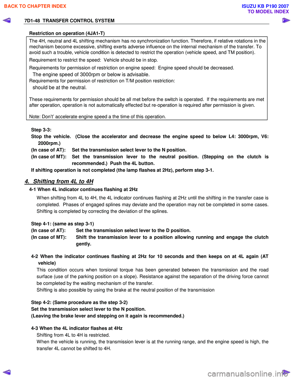
7D1-48 TRANSFER CONTROL SYSTEM
Restriction on operation (4JA1-T)
The 4H, neutral and 4L shifting mechanism has no synchronization function. Therefore, if relative rotations in the
mechanism become excessive, shifting exerts adverse influence on the internal mechanism of the transfer. To
avoid such a trouble, vehicle condition is detected to restrict the operation (vehicle speed, and TM position).
Requirement to restrict the speed: Vehicle should be in stop.
Requirements for permission of restriction on engine speed: Engine speed should be decreased.
The engine speed of 3000rpm or below is advisable.
Requirements for permission of restriction on T/M position restriction:
should be at the neutral.
These requirements for permission should be all met before the switch is operated. If the requirements are met
after operation, operation is not automatically effected but re-operation is required after permission is given.
Note: Don’t’ accelerate engine speed a the time of this operation.
Step 3-3:
Stop the vehicle. (Close the accelerator and decrease the engine speed to below L4: 3000rpm, V6: 2000rpm.)
(In case of AT): Set the transmission select lever to the N position.
(In case of MT): Set the transmission lever to the neutral position. (Stepping on the clutch is recommended.) Push the 4L button.
If shifting operation is not completed (the lamp flashes at 2Hz), perform step 3-1.
4. Shifting from 4L to 4H
4-1 When 4L indicator continues flashing at 2Hz
W hen shifting from 4L to 4H, the 4L indicator continues flashing at 2Hz until the shifting in the transfer case is
completed. Phases of engaged splines may deviate and the operation may not be completed in some cases.
Shifting is completed by correcting the deviation of the splines.
Step 4-1: (same as step 3-1)
(In case of AT): Set the transmission select lever to the D position.
(In case of MT): Shift the transmission lever to a position allowing running and engage the clutch gently.
4-2 When the indicator continues flashing at 2Hz for 10 seconds and then keeps on at 4L again (AT
vehicle)
This condition occurs when torsional torque has been generated between the transmission and the road
surface (use of the parking position on a slope). Resistance against the separation of the driving force cannot
be completed by the waiting mechanism of the transfer.
Shifting is also possible by using the brake at the neutral position of the transmission
Step 4-2: (Same procedure as the step 3-2)
Set the transmission select lever to the N position.
(Leaving the brake lever and stepping on it again is recommended.)
4-3 When the 4L indicator flashes at 4Hz
Shifting from 4L to 4H is restricted.
W hen the vehicle is running, the transmission lever is at the running range, and the engine speed is high, the
transfer 4L cannot be shifted to 4H.
BACK TO CHAPTER INDEX
TO MODEL INDEX
ISUZU KB P190 2007
Page 5594 of 6020
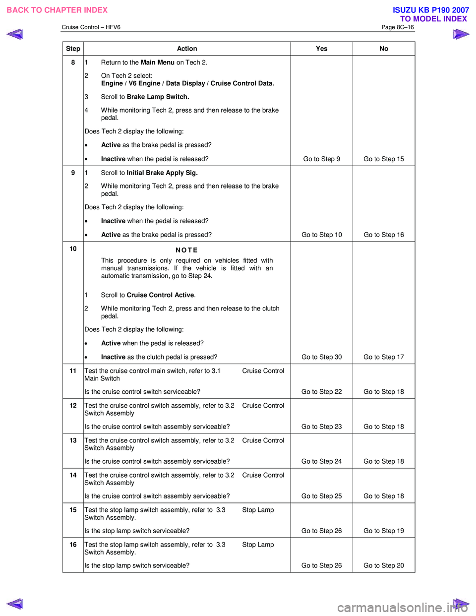
Cruise Control – HFV6 Page 8C–16
Step Action Yes No
8 1 Return to the Main Menu on Tech 2.
2 On Tech 2 select: Engine / V6 Engine / Data Display / Cruise Control Data.
3 Scroll to Brake Lamp Switch.
4 While monitoring Tech 2, press and then release to the brake pedal.
Does Tech 2 display the following:
• Active as the brake pedal is pressed?
• Inactive when the pedal is released? Go to Step 9 Go to Step 15
9 1 Scroll to Initial Brake Apply Sig.
2 While monitoring Tech 2, press and then release to the brake pedal.
Does Tech 2 display the following:
• Inactive when the pedal is released?
• Active as the brake pedal is pressed? Go to Step 10 Go to Step 16
10
NOTE
This procedure is only required on vehicles fitted with
manual transmissions. If the vehicle is fitted with an
automatic transmission, go to Step 24.
1 Scroll to Cruise Control Active .
2 While monitoring Tech 2, press and then release to the clutch pedal.
Does Tech 2 display the following:
• Active when the pedal is released?
• Inactive as the clutch pedal is pressed?
Go to Step 30 Go to Step 17
11 Test the cruise control main switch, refer to 3.1 Cruise Control
Main Switch
Is the cruise control switch serviceable? Go to Step 22 Go to Step 18
12 Test the cruise control switch assembly, refer to 3.2 Cruise Control
Switch Assembly
Is the cruise control switch assembly serviceable? Go to Step 23 Go to Step 18
13 Test the cruise control switch assembly, refer to 3.2 Cruise Control
Switch Assembly
Is the cruise control switch assembly serviceable? Go to Step 24 Go to Step 18
14 Test the cruise control switch assembly, refer to 3.2 Cruise Control
Switch Assembly
Is the cruise control switch assembly serviceable? Go to Step 25 Go to Step 18
15 Test the stop lamp switch assembly, refer to 3.3 Stop Lamp
Switch Assembly.
Is the stop lamp switch serviceable? Go to Step 26 Go to Step 19
16 Test the stop lamp switch assembly, refer to 3.3 Stop Lamp
Switch Assembly.
Is the stop lamp switch serviceable? Go to Step 26 Go to Step 20
BACK TO CHAPTER INDEX
TO MODEL INDEXISUZU KB P190 2007
Page 5595 of 6020
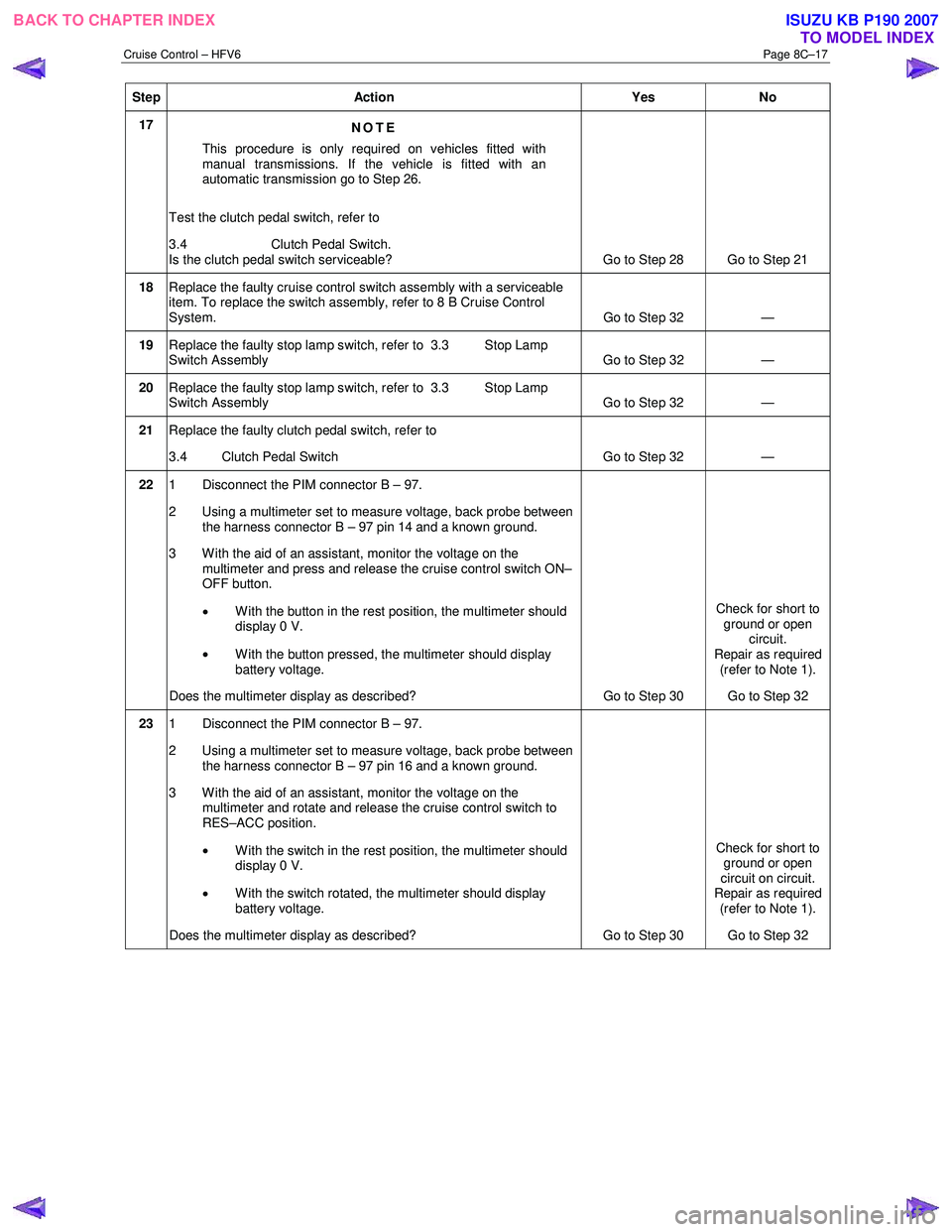
Cruise Control – HFV6 Page 8C–17
Step Action Yes No
17
NOTE
This procedure is only required on vehicles fitted with
manual transmissions. If the vehicle is fitted with an
automatic transmission go to Step 26.
Test the clutch pedal switch, refer to
3.4 Clutch Pedal Switch.
Is the clutch pedal switch serviceable? Go to Step 28 Go to Step 21
18 Replace the faulty cruise control switch assembly with a serviceable
item. To replace the switch assembly, refer to 8 B Cruise Control
System. Go to Step 32 —
19 Replace the faulty stop lamp switch, refer to 3.3 Stop Lamp
Switch Assembly Go to Step 32 —
20 Replace the faulty stop lamp switch, refer to 3.3 Stop Lamp
Switch Assembly Go to Step 32 —
21
Replace the faulty clutch pedal switch, refer to
3.4 Clutch Pedal Switch Go to Step 32 —
22 1 Disconnect the PIM connector B – 97.
2 Using a multimeter set to measure voltage, back probe between the harness connector B – 97 pin 14 and a known ground.
3 W ith the aid of an assistant, monitor the voltage on the multimeter and press and release the cruise control switch ON–
OFF button.
• W ith the button in the rest position, the multimeter should
display 0 V.
• W ith the button pressed, the multimeter should display
battery voltage.
Does the multimeter display as described? Go to Step 30 Check for short to
ground or open circuit.
Repair as required
(refer to Note 1).
Go to Step 32
23 1 Disconnect the PIM connector B – 97.
2 Using a multimeter set to measure voltage, back probe between the harness connector B – 97 pin 16 and a known ground.
3 With the aid of an assistant, monitor the voltage on the multimeter and rotate and release the cruise control switch to
RES–ACC position.
• With the switch in the rest position, the multimeter should
display 0 V.
• With the switch rotated, the multimeter should display
battery voltage.
Does the multimeter display as described? Go to Step 30 Check for short to
ground or open
circuit on circuit.
Repair as required
(refer to Note 1).
Go to Step 32
BACK TO CHAPTER INDEX TO MODEL INDEXISUZU KB P190 2007