2007 ISUZU KB P190 transfer case
[x] Cancel search: transfer casePage 3959 of 6020
Automatic Transmission – 4L60E – On-vehicle Servicing Page 7C4–46
Reinstall
1 If required on 4W D vehicle, reinstall the transfer case, refer to 7D Transfer Case and Adaptor Housing.
2 Ensure the transmission and the engine mating surfaces are clean and free of burrs.
3 Lubricate the torque converter spigot (7) with a small amount of high temperature wheel bearing grease, refer to Figure 7C4 – 62.
4 Install a new filler tube seal into the transmission case.
Support the transmission while installing the
attaching bolts to avoid damage to the torque
converter and flexplate. Do not have the
transmission hanging.
5 Bring the transmission up to the engine, inserting the filler tube and ensuring the locating dowels completely enter the torque converter housing.
6 Reconnect the breather hose to the top of the transmission case.
NOTE
The bolts attaching the torque converter housing
are facing forward except for the bolt in position ℑ
which is facing rearward.
7 With the transmission supported, install the bolt (1), nine places, attaching the torque converter housing to the engine and tighten to the correct torque specification following the sequence shown in
within Figure 7C4 – 62.
Torque converter housing attaching
bolt torque specification .......................... 52.0 – 66.0 Nm
8 Remove the access hole cover plate from the lower surface of the housing and push the torque converter forward to meet the flexplate, then hand start three new bolts (2) before tightening to the correct torque specification.
Reinstall the access hole cover plate.
Torque converter to flexplate attaching
bolt torque specification .......................... 60.0 – 70.0 Nm
9 Reinstall the bolt (3) and torque converter cover (4) on the transmission right-hand side and the bolt (5) and torque converter cover (6) on the transmission left-hand side, tighten the bolts to the correct torque specification.
Torque converter cover attaching
bolt torque specification .......................... 12.0 – 16.0 Nm
10 Reinstall the transmission fluid lines, refer to 3.17 Transmission Cooler Line/Hose Assemblies.
Prior to connecting the harness connector to
the transmission, check that all pins and
seals are in sound condition and the dust
boot is not torn or damaged.
11 Reconnect the transmission harness connector to the transmission as follows: a Push straight down on the connector body until a click is heard.
b Reinstall the dust boot ensuring it is correctly located.
12 Attach the harness clips to the right-hand and left-hand sides of the transmission case, refer to 12O Fuses, Relays and Wiring Harnesses.
13 On 4WD vehicle, connect the harness two clips from the upper side of the transfer case.
BACK TO CHAPTER INDEX
TO MODEL INDEX
ISUZU KB P190 2007
Page 3960 of 6020
Automatic Transmission – 4L60E – On-vehicle Servicing Page 7C4–47
14 Reconnect the fuel and EVAP pipes three brackets and clips, refer to 6C Fuel System – V6.
15 Reinstall the following components:
a Starter motor, refer to 6D1-2 Starting System.
b Transmission support, refer to 3.7 Transmission Support and Mount.
c Front and centre exhaust assemblies, refer to 6F Exhaust System.
d Rear propeller shaft and for 4WD front propeller shaft, refer to 4A Propeller Shaft.
16 Reconnect the harness connectors to the following: a Vehicle speed sensor, refer to 3.5 Vehicle Speed Sensor.
b Neutral start and back-up switch, refer to 3.4 Neutral Start and Back-up Lamp Switch.
c For the following on 4W D vehicles, refer to 7D Transfer Case and Adaptor Housing:
• neutral switch,
• 2WD – 4WD shift actuator switch,
• speed sensor.
17 Reinstall the selector cable to the transmission external manual shaft linkage, secure the selector cable to the bracket and attach the heat shield to the neutral start and back-up lamp switch, refer to 3.3 Selector Cable
Assembly.
18 Perform a reverse flush of the cooler lines and a flow rate test, refer to 2.2 Reverse Flush and Flow Rate, if either of the following applies:
• the transmission fluid is contaminated,
• the transmission has been replaced,
• the torque converter has been replaced, or
• the transmission oil pump has been replaced.
19 Lower the vehicle to the ground.
20 If required, top up the transmission fluid level (cold).
21 Reconnect the battery ground lead.
22 Start the engine and check for any fluid leaking at the fittings. If a leak is found, stop the engine and rectify the leak.
23 Road test until the transmission has reached operating temperature. Re-check the fluid level and for any fluid leaks, refer to 2.1 Transmission Fluid.
3.19 Transmission Control Module
Remove
1 Ensure the ignition switch is in the OFF position.
2 Disconnect the connector (1) from the transmission control module (TCM) (2) as follows, refer to Figure 7C4 – 63: a remove the securing pin (3),
b press the locking tab and swing the lever (4) to free the connector,
c remove the connector.
3 Remove the four bolts (5) and nuts (6), then the TCM from the mounting bracket (7).
4 If required, remove the two nuts (8) and the mounting bracket from the firewall.
BACK TO CHAPTER INDEX
TO MODEL INDEX
ISUZU KB P190 2007
Page 4117 of 6020
7A3-32 ON-VEHICLE SERVICE (AW30–40LE)
Shift Solenoid and Lock-Up Solenoid
Removal
Preparation:
• Disconnect negative (–) battery cable.
• Drain the fluid.
Refer to ATF REPLACEMENT in this section.
1. Remove oil lever gage and oil filler tube.
2. Support transfer case (4
×4) or rear cover (4×2)
with a transmission jack.
3. Remove engine rear mounting nuts.
F07RW 008
4. Remove fule pipe heat protector on tansmission
corssmenber.
5. Remove fuel pipe from the crossmenber.
6. Remove transmission crossmenber.
7. Remove the nineteen bolts.
8. Remove oil pan, using seal cutter 5-8840-2153-0.
RUW 37ASH002901
NOTE: Do not turn over the transmission as this will
contaminate the valve body with foreign materials in the
bottom of the oil pan.
Remove oil pan by lifting the transmission case.
Oil pan seal cutter: 5-8840-2153-0
Examine particles in oil pan
Remove the magnet and use it to collect any steel
chips.
Look carefully at the chips and particles in the oil
pan and on the magnet to anticipate what type o
f
wear you will find in the transmission:
Steel (magnetic) .................. bearing, gear and
clutch plate wear
Brass (non-magnetic).......... bushing wear
240RY00008
9. Remove the oil strainer assembly.
244RY00003
BACK TO CHAPTER INDEX
TO MODEL INDEX
ISUZU KB P190 2007
Page 4122 of 6020
ON-VEHICLE SERVICE (AW30–40LE) 7A3-37
Rear Oil Seal (Adapter Housing, 4×
××
×4)
Removal
1. Remove the front and rear propeller shaft assembly
from the transfer case.
2. Remove the transfer case assembly from the transmission case.
Refer to Section 7D TRANSFER.
3. Using a screwdriver, remove the rear oil seal.
Installation
1. Apply ATF to a new rear oil seal lip.
2. Using oil seal installer, install the rear oil seal to the adapter housing.
Oil seal installer : 5-8840-2282-0
240RY00003
3. Install the transfer case assembly.
Refer to section 7D TRANSFER.
4. Install the front and rear propeller shaft assembly.
Torque (Propeller shaft flange bolt) :
63 N ⋅
⋅⋅
⋅
m (6.4 kgf ⋅
⋅⋅
⋅
m/46 Ib ⋅
⋅⋅
⋅
ft)
BACK TO CHAPTER INDEX
TO MODEL INDEX
ISUZU KB P190 2007
Page 4273 of 6020
7A1-34 CONSTRUCTION AND FUNCTION
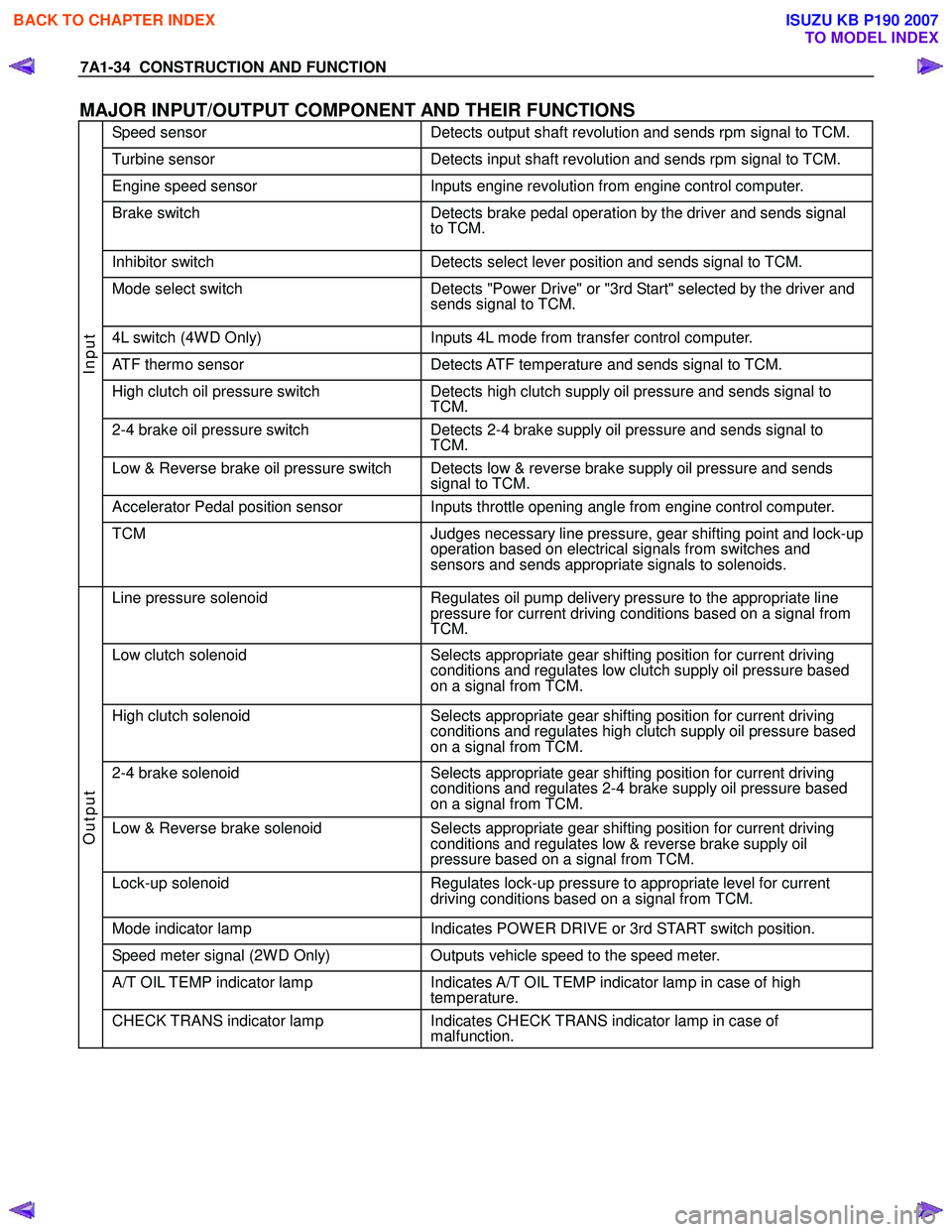
MAJOR INPUT/OUTPUT COMPONENT AND THEIR FUNCTIONS
Speed sensor Detects output shaft revolution and sends rpm signal to TCM.
Turbine sensor Detects input shaft revolution and sends rpm signal to TCM.
Engine speed sensor Inputs engine revolution from engine control computer.
Brake switch Detects brake pedal operation by the driver and sends signal
to TCM.
Inhibitor switch Detects select lever position and sends signal to TCM.
Mode select switch Detects "Power Drive" or "3rd Start" selected by the driver and
sends signal to TCM.
4L switch (4W D Only) Inputs 4L mode from transfer control computer.
ATF thermo sensor Detects ATF temperature and sends signal to TCM.
High clutch oil pressure switch Detects high clutch supply oil pressure and sends signal to
TCM.
2-4 brake oil pressure switch Detects 2-4 brake supply oil pressure and sends signal to
TCM.
Low & Reverse brake oil pressure switch Detects low & reverse brake supply oil pressure and sends signal to TCM.
Accelerator Pedal position sensor Inputs throttle opening angle from engine control computer.
Input
TCM Judges necessary line pressure, gear shifting point and lock-up
operation based on electrical signals from switches and
sensors and sends appropriate signals to solenoids.
Line pressure solenoid Regulates oil pump delivery pressure to the appropriate line
pressure for current driving conditions based on a signal from
TCM.
Low clutch solenoid Selects appropriate gear shifting position for current driving
conditions and regulates low clutch supply oil pressure based
on a signal from TCM.
High clutch solenoid Selects appropriate gear shifting position for current driving
conditions and regulates high clutch supply oil pressure based
on a signal from TCM.
2-4 brake solenoid Selects appropriate gear shifting position for current driving
conditions and regulates 2-4 brake supply oil pressure based
on a signal from TCM.
Low & Reverse brake solenoid Selects appropriate gear shifting position for current driving
conditions and regulates low & reverse brake supply oil
pressure based on a signal from TCM.
Lock-up solenoid Regulates lock-up pressure to appropriate level for current
driving conditions based on a signal from TCM.
Mode indicator lamp Indicates POW ER DRIVE or 3rd START switch position.
Speed meter signal (2W D Only) Outputs vehicle speed to the speed meter.
A/T OIL TEMP indicator lamp Indicates A/T OIL TEMP indicator lamp in case of high
temperature.
Output
CHECK TRANS indicator lamp Indicates CHECK TRANS indicator lamp in case of
malfunction.
BACK TO CHAPTER INDEX
TO MODEL INDEX
ISUZU KB P190 2007
Page 4308 of 6020
7A2-24 TRANSMISSION CONTROL SYSTEM (JR405E)
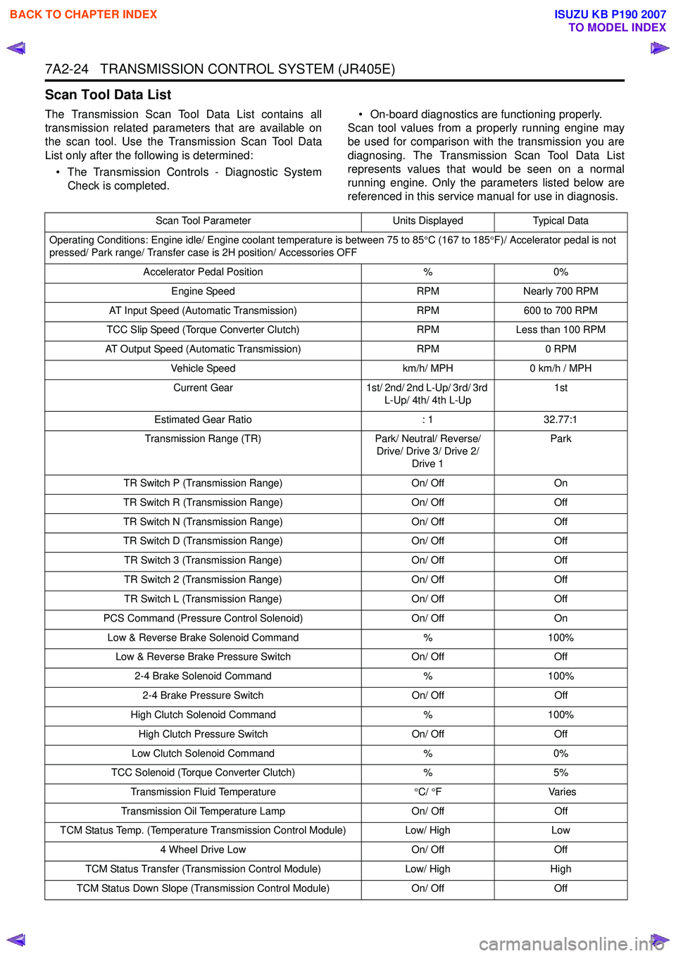
Scan Tool Data List
The Transmission Scan Tool Data List contains all
transmission related parameters that are available on
the scan tool. Use the Transmission Scan Tool Data
List only after the following is determined:
• The Transmission Controls - Diagnostic System Check is completed. • On-board diagnostics are functioning properly.
Scan tool values from a properly running engine may
be used for comparison with the transmission you are
diagnosing. The Transmission Scan Tool Data List
represents values that would be seen on a normal
running engine. Only the parameters listed below are
referenced in this service manual for use in diagnosis.
Scan Tool Parameter Units DisplayedTypical Data
Operating Conditions: Engine idle/ Engine coolant temperature is between 75 to 85 °C (167 to 185 °F)/ Accelerator pedal is not
pressed/ Park range/ Transfer case is 2H position/ Accessories OFF
Accelerator Pedal Position %0%
Engine Speed RPMNearly 700 RPM
AT Input Speed (Automatic Transmission) RPM600 to 700 RPM
TCC Slip Speed (Torque Converter Clutch) RPMLess than 100 RPM
AT Output Speed (Automatic Transmission) RPM0 RPM
Vehicle Speed km/h/ MPH0 km/h / MPH
Current Gear 1st/ 2nd/ 2nd L-Up/ 3rd/ 3rd
L-Up/ 4th/ 4th L-Up 1st
Estimated Gear Ratio : 132.77:1
Transmission Range (TR) Park/ Neutral/ Reverse/
Drive/ Drive 3/ Drive 2/ Drive 1 Park
TR Switch P (Transmission Range) On/ OffOn
TR Switch R (Transmission Range) On/ OffOff
TR Switch N (Transmission Range) On/ OffOff
TR Switch D (Transmission Range) On/ OffOff
TR Switch 3 (Transmission Range) On/ OffOff
TR Switch 2 (Transmission Range) On/ OffOff
TR Switch L (Transmission Range) On/ OffOff
PCS Command (Pressure Control Solenoid) On/ OffOn
Low & Reverse Brake Solenoid Command %100%
Low & Reverse Brake Pressure Switch On/ OffOff
2-4 Brake Solenoid Command %100%
2-4 Brake Pressure Switch On/ OffOff
High Clutch Solenoid Command %100%
High Clutch Pressure Switch On/ OffOff
Low Clutch Solenoid Command %0%
TCC Solenoid (Torque Converter Clutch) %5%
Transmission Fluid Temperature °C/ °F V arie s
Transmission Oil Temperature Lamp On/ OffOff
TCM Status Temp. (Temperature Transmission Control Module) Low/ HighLow
4 Wheel Drive Low On/ OffOff
TCM Status Transfer (Transmission Control Module) Low/ HighHigh
TCM Status Down Slope (Transmission Control Module) On/ OffOff
BACK TO CHAPTER INDEX
TO MODEL INDEX
ISUZU KB P190 2007
Page 4310 of 6020
7A2-26 TRANSMISSION CONTROL SYSTEM (JR405E)
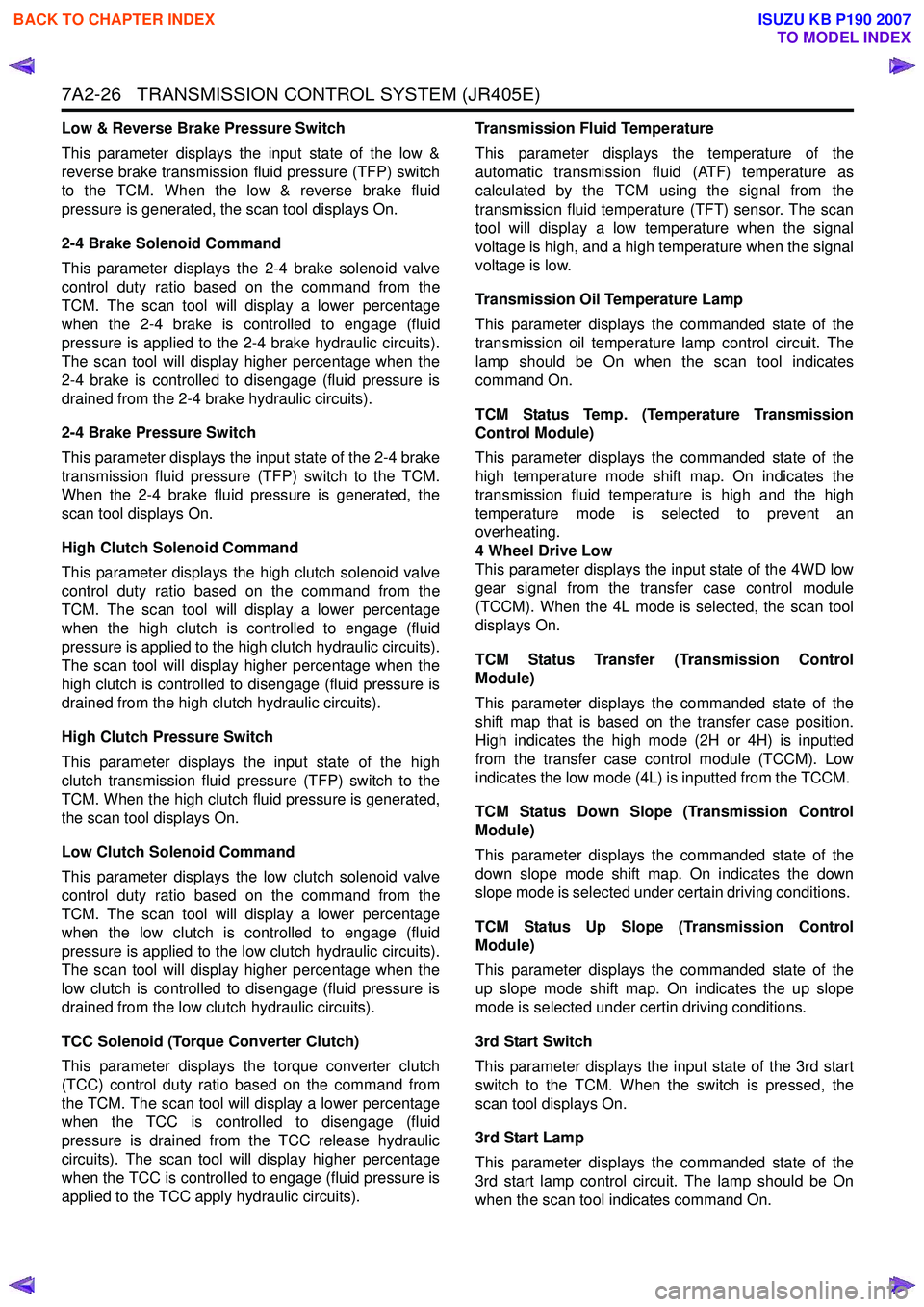
Low & Reverse Brake Pressure Switch
This parameter displays the input state of the low &
reverse brake transmission fluid pressure (TFP) switch
to the TCM. When the low & reverse brake fluid
pressure is generated, the scan tool displays On.
2-4 Brake Solenoid Command
This parameter displays the 2-4 brake solenoid valve
control duty ratio based on the command from the
TCM. The scan tool will display a lower percentage
when the 2-4 brake is controlled to engage (fluid
pressure is applied to the 2-4 brake hydraulic circuits).
The scan tool will display higher percentage when the
2-4 brake is controlled to disengage (fluid pressure is
drained from the 2-4 brake hydraulic circuits).
2-4 Brake Pressure Switch
This parameter displays the input state of the 2-4 brake
transmission fluid pressure (TFP) switch to the TCM.
When the 2-4 brake fluid pressure is generated, the
scan tool displays On.
High Clutch Solenoid Command
This parameter displays the high clutch solenoid valve
control duty ratio based on the command from the
TCM. The scan tool will display a lower percentage
when the high clutch is controlled to engage (fluid
pressure is applied to the high clutch hydraulic circuits).
The scan tool will display higher percentage when the
high clutch is controlled to disengage (fluid pressure is
drained from the high clutch hydraulic circuits).
High Clutch Pressure Switch
This parameter displays the input state of the high
clutch transmission fluid pressure (TFP) switch to the
TCM. When the high clutch fluid pressure is generated,
the scan tool displays On.
Low Clutch Solenoid Command
This parameter displays the low clutch solenoid valve
control duty ratio based on the command from the
TCM. The scan tool will display a lower percentage
when the low clutch is controlled to engage (fluid
pressure is applied to the low clutch hydraulic circuits).
The scan tool will display higher percentage when the
low clutch is controlled to disengage (fluid pressure is
drained from the low clutch hydraulic circuits).
TCC Solenoid (Torque Converter Clutch)
This parameter displays the torque converter clutch
(TCC) control duty ratio based on the command from
the TCM. The scan tool will display a lower percentage
when the TCC is controlled to disengage (fluid
pressure is drained from the TCC release hydraulic
circuits). The scan tool will display higher percentage
when the TCC is controlled to engage (fluid pressure is
applied to the TCC apply hydraulic circuits). Transmission Fluid Temperature
This parameter displays the temperature of the
automatic transmission fluid (ATF) temperature as
calculated by the TCM using the signal from the
transmission fluid temperature (TFT) sensor. The scan
tool will display a low temperature when the signal
voltage is high, and a high temperature when the signal
voltage is low.
Transmission Oil Temperature Lamp
This parameter displays the commanded state of the
transmission oil temperature lamp control circuit. The
lamp should be On when the scan tool indicates
command On.
TCM Status Temp. (Temperature Transmission
Control Module)
This parameter displays the commanded state of the
high temperature mode shift map. On indicates the
transmission fluid temperature is high and the high
temperature mode is selected to prevent an
overheating.
4 Wheel Drive Low
This parameter displays the input state of the 4WD low
gear signal from the transfer case control module
(TCCM). When the 4L mode is selected, the scan tool
displays On.
TCM Status Transfer (Transmission Control
Module)
This parameter displays the commanded state of the
shift map that is based on the transfer case position.
High indicates the high mode (2H or 4H) is inputted
from the transfer case control module (TCCM). Low
indicates the low mode (4L) is inputted from the TCCM.
TCM Status Down Slope (Transmission Control
Module)
This parameter displays the commanded state of the
down slope mode shift map. On indicates the down
slope mode is selected under certain driving conditions.
TCM Status Up Slope (Transmission Control
Module)
This parameter displays the commanded state of the
up slope mode shift map. On indicates the up slope
mode is selected under certin driving conditions.
3rd Start Switch
This parameter displays the input state of the 3rd start
switch to the TCM. When the switch is pressed, the
scan tool displays On.
3rd Start Lamp
This parameter displays the commanded state of the
3rd start lamp control circuit. The lamp should be On
when the scan tool indicates command On.
BACK TO CHAPTER INDEX
TO MODEL INDEX
ISUZU KB P190 2007
Page 4830 of 6020
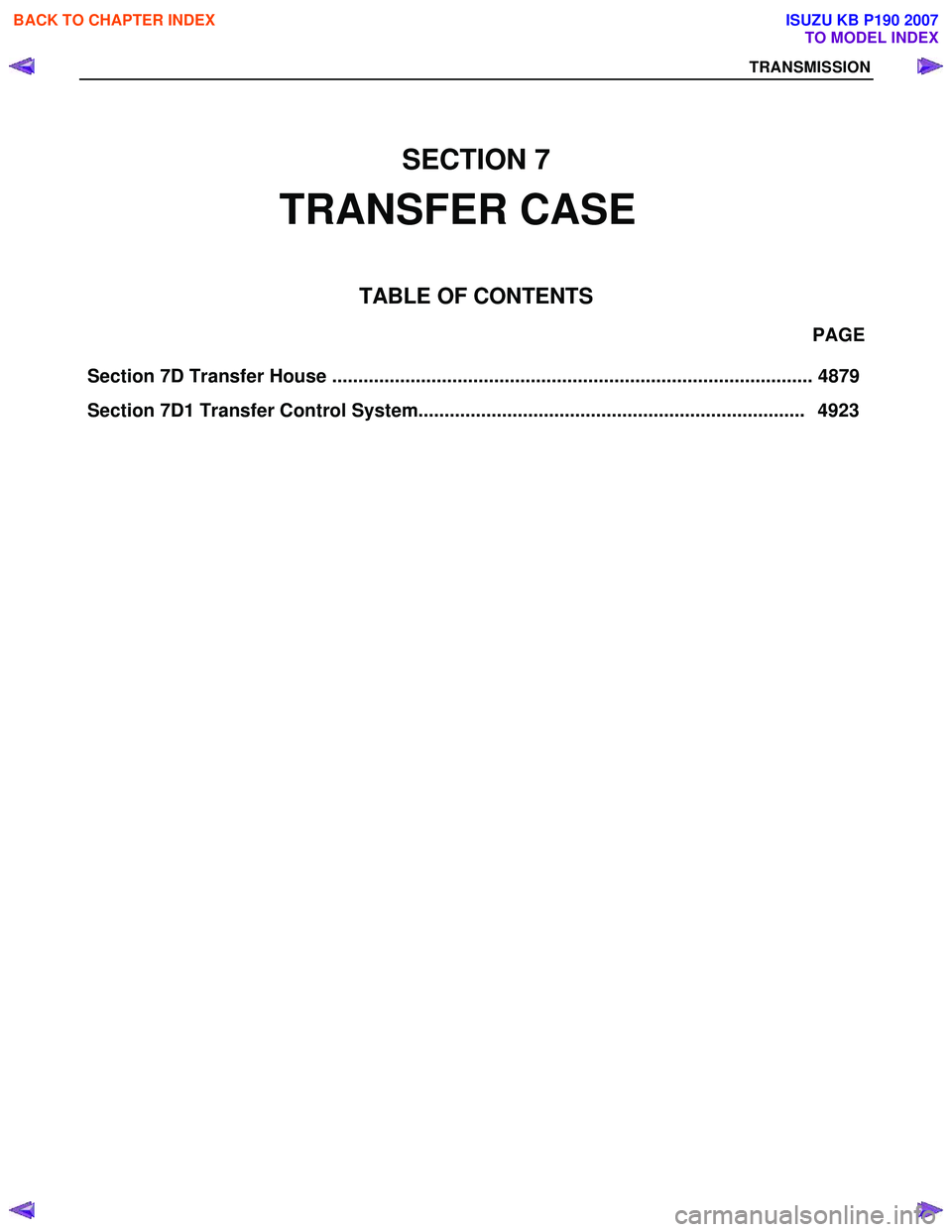
Section 7D Transfer House ............................................................................................ 4879 PAGE
Section 7D1 Transfer Control System.......................................................................... 4923
SECTION 7
TRANSFER CASE
TA BLE OF CONTENTS
TRANSMISSION
BACK TO CHAPTER INDEX
TO MODEL INDEX
ISUZU KB P190 2007