2007 ISUZU KB P190 transfer case
[x] Cancel search: transfer casePage 574 of 6020

4C1-70 FRONT WHEEL DRIVE
PROPELLER SHAFT 1. NOISE
Checkpoint Trouble Cause Countermeasure
Spider bearingReplaceWorn or jammed
ReplaceDamaged or worn
NG
NG
OKYoke spline
2. VIBRATION
Shaft balanceAdjustUnbalance
ReplaceIncorrect
NG
NG
OKShaft runout
Transmission rear housing
bushing, transfer case
housing bushing
ReplaceWorn
NG
OK
Yoke splineReplaceJammed
NG
OK
BACK TO CHAPTER INDEX
TO MODEL INDEX
ISUZU KB P190 2007
Page 607 of 6020

5A-14 BRAKE CONTROL SYSTEM
Connector List
No. Connector face No. Connector face
B-23
White
Meter-A C-36
SilverEngine room - LH ; Ground
B-24
White
Meter-B C-44
WhiteStoplight switch
B-48
Black
G sensor C-53
OrangeABS sensor Front-RH
B-54
White
J/B I2 C-54
OrangeABS sensor Front-LH
B-56
White
J/B I4 C-67
Black
EHCU
B-58
Black
Data link connector C-107
WhiteJ/B E2
B-62
White
Ignition switch (IGSUB : G1) C-108
WhiteJ/B E1
B-63
White
Ignition switch (IGSUB : G2) C-109
SilverBody-LH ; ground
B-82
Silver
W eld splice 6 (Ground) C-111
BlackTransfer case control module
C-2
Silver
Engine room - RH ground F-4
Gray ABS sensor
BACK TO CHAPTER INDEX
TO MODEL INDEX
ISUZU KB P190 2007
Page 1967 of 6020
6E-350 ENGINE CONTROL SYSTEM (4JK1/4JJ1)
• The hardware key is plugged into the computerport.
• Vehicle system voltage: - There are no charging system concerns. Allcharging system concerns must be repaired
before programming the ECM.
- The battery voltage is greater than 12 volts but less than 16 volts. The battery must be fully
charged before programming the ECM.
- A battery charger is NOT connected to the vehicles battery. Incorrect system voltage or
voltage fluctuations from a battery charger may
cause programming failure or ECM damage.
- Turn OFF or disable any system that may put a load on the vehicles battery. Turn OFF or
disable systems such as:
◊ Heating, ventilation, and air conditioning
(HVAC) systems
◊ Headlights
◊ Room lights
◊ Accessory equipment
• The ignition switch is in the proper position. The scan tool prompts you to turn ON the ignition, with
the engine OFF. DO NOT change the position of
the ignition switch during the programming
procedure unless instructed to do so.
• All tool connections are secure: - The RS-232 cable
- The connection at the DLC
- The voltage supply circuits
• DO NOT disturb the tool harnesses while programming. If an interruption occurs during the
programming procedure, programming failure or
ECM damage may occur.
• If you are performing the Pass-Thru programming procedure using a notebook computer without the
power cord, ensure that the internal battery is fully
charged.
Service Programming System (SPS)
(Remote Procedure)
Notice: Some module will not accept SPS remote
procedure using 10MB PCMCIA card. In such case,
use 32MB PCMCIA card or SPS pass-thru procedure.
The Remote SPS method is a three-step process that
involves the following procedures:
1. Connecting the scan tool to the vehicle and obtaining the information from the ECM.
2. Connecting the scan tool to the terminal and downloading a new calibration file from the
terminal into the scan tool memory.
3. Reconnecting the scan tool to the vehicle and uploading the new calibration file into the ECM. Performing the Remote Procedure
1. Connect a scan tool to the vehicle and obtain the ECM information using the following procedure:
Notice: Ensure the ECM is installed in the vehicle and
the battery is fully charged before programming.
a. Install a scan tool.
b. Turn ON the ignition, with the engine OFF.
c. Select Service Programming System (SPS) > Request Info.
d. If there is already stored in the scan tool, the existing data is displayed on the screen. The
scan tool asks user to keep existing data "Keep
Data" or "Continue" to request new vehicle
information from the ECM. If there is no data in
the scan tool, it will immediately start vehicle
identification.
e. Select the vehicle description by following the on-screen instructions based on stamped VIN
or affixed VIN plate on the vehicle.
f. During obtaining information, the scan tool is receiving information from all modules at the
same time. But only ECM information is
displayed on the screen.
g. Turn OFF all accessories and press "Okay".
h. Verify that the correct VIN is displayed on the scan tool. If the VIN is incorrect or no VIN,
record the correct VIN.
2. Turn OFF the ignition.
3. Turn OFF the scan tool and disconnect from the vehicle.
4. Transfer the data from the terminal to the scan tool using the following procedure:
Notice: The TIS supports service programming with
the Tech 2 scan tool only.
a. Connect the scan tool to the terminal.
b. Launch the TIS application.
c. Select the Service Programming System at the main screen.
d. Highlight the following information on the Select Diagnostic Tool and Programming Process
screen, then click "Next".
• Select Diagnostic Tool - Tech 2
• Select Programming Process - Identify whether an existing ECM is being
reprogrammed or an ECM is being replaced
with a new one
• Select ECU Location - Vehicle
e. Verify the connections on the Preparing for Communication screen, then click "Next".
f. Verify the VIN on the Validate Vehicle Identification Number (VIN) screen, then click
"Next".
BACK TO CHAPTER INDEX
TO MODEL INDEX
ISUZU KB P190 2007
Page 2225 of 6020
ENGINE DRIVEABILITY AND EMISSIONS 6E–55
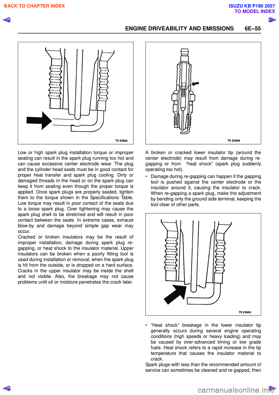
Low or high spark plug installation torque or improper
seating can result in the spark plug running too hot and
can cause excessive center electrode wear. The plug
and the cylinder head seats must be in good contact for
proper heat transfer and spark plug cooling. Dirty or
damaged threads in the head or on the spark plug can
keep it from seating even though the proper torque is
applied. Once spark plugs are properly seated, tighten
them to the torque shown in the Specifications Table.
Low torque may result in poor contact of the seats due
to a loose spark plug. Over tightening may cause the
spark plug shell to be stretched and will result in poor
contact between the seats. In extreme cases, exhaust
blow-by and damage beyond simple gap wear may
occur.
Cracked or broken insulators may be the result of
improper installation, damage during spark plug re-
gapping, or heat shock to the insulator material. Upper
insulators can be broken when a poorly fitting tool is
used during installation or removal, when the spark plug
is hit from the outside, or is dropped on a hard surface.
Cracks in the upper insulator may be inside the shell
and not visible. Also, the breakage may not cause
problems until oil or moisture penetrates the crack later. A broken or cracked lower insulator tip (around the
center electrode) may result from damage during re-
gapping or from “heat shock” (spark plug suddenly
operating too hot).
• Damage during re-gapping can happen if the gapping tool is pushed against the center electrode or the
insulator around it, causing the insulator to crack.
When re-gapping a spark plug, make the adjustment
by bending only the ground side terminal, keeping the
tool clear of other parts.
• “Heat shock” breakage in the lower insulator tip generally occurs during several engine operating
conditions (high speeds or heavy loading) and may
be caused by over-advanced timing or low grade
fuels. Heat shock refers to a rapid increase in the tip
temperature that causes the insulator material to
crack.
Spark plugs with less than the recommended amount of
service can sometimes be cleaned and re-gapped, then
BACK TO CHAPTER INDEX
TO MODEL INDEX
ISUZU KB P190 2007
Page 2668 of 6020

Engine Mechanical – V6 Page 6A1–189
28 Remove the centre exhaust pipe (1), refer to 6F
Exhaust System - V6 - V6.
Figure 6A1 – 327
29 Disconnect the two post-catalytic converter oxygen sensor wiring harness connectors, 1 each bank.
Figure 6A1 – 328
30 Disconnect the two pre-catalytic converter oxygen sensor wiring harness connectors, 1 each bank.
31 Remove the front exhaust flange nuts, three each bank.
32 Remove the front left-hand exhaust pipe from the rubber mount.
33 Remove the front exhaust pipes from the vehicle, for further information, refer to 6F Exhaust System - V6.
Figure 6A1 – 329
34 Remove the transfer case from the vehicle (4W D Only), refer to 7D Transfer Case and Adaptor Housing.
BACK TO CHAPTER INDEX
TO MODEL INDEX
ISUZU KB P190 2007
Page 2709 of 6020
Engine Mechanical – V6 Page 6A1–230
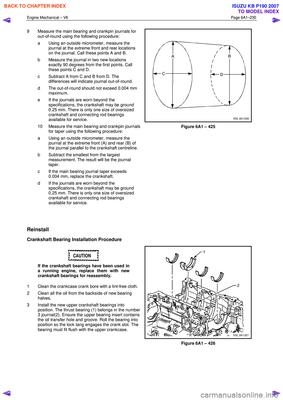
9 Measure the main bearing and crankpin journals for
out-of-round using the following procedure:
a Using an outside micrometer, measure the journal at the extreme front and rear locations
on the journal. Call these points A and B.
b Measure the journal in two new locations exactly 90 degrees from the first points. Call
these points C and D.
c Subtract A from C and B from D. The differences will indicate journal out-of-round.
d The out-of-round should not exceed 0.004 mm maximum.
e If the journals are worn beyond the specifications, the crankshaft may be ground
0.25 mm. There is only one size of oversized
crankshaft and connecting rod bearings
available for service.
10 Measure the main bearing and crankpin journals for taper using the following procedure:
a Using an outside micrometer, measure the journal at the extreme front (A) and rear (B) of
the journal parallel to the crankshaft centreline.
b Subtract the smallest from the largest measurement. The result will be the journal
taper.
c If the main bearing journal taper exceeds 0.004 mm, replace the crankshaft.
d If the journals are worn beyond the specifications, the crankshaft may be ground
0.25 mm. There is only one size of oversized
crankshaft and connecting rod bearings
available for service.
Figure 6A1 – 425
Reinstall
Crankshaft Bearing Installation Procedure
CAUTION
If the crankshaft bearings have been used in
a running engine, replace them with new
crankshaft bearings for reassembly.
1 Clean the crankcase crank bore with a lint-free cloth.
2 Clean all the oil from the backside of new bearing halves.
3 Install the new upper crankshaft bearings into position. The thrust bearing (1) belongs in the number
3 journal(2). Ensure the upper bearing insert contains
the oil transfer hole and groove. Roll the bearing into
position so the lock tang engages the crank slot. The
bearing must fit flush with the upper crankcase.
Figure 6A1 – 426
BACK TO CHAPTER INDEX
TO MODEL INDEX
ISUZU KB P190 2007
Page 3021 of 6020
Engine Mechanical – V6 Page 6A1–244
Page 6A1–244
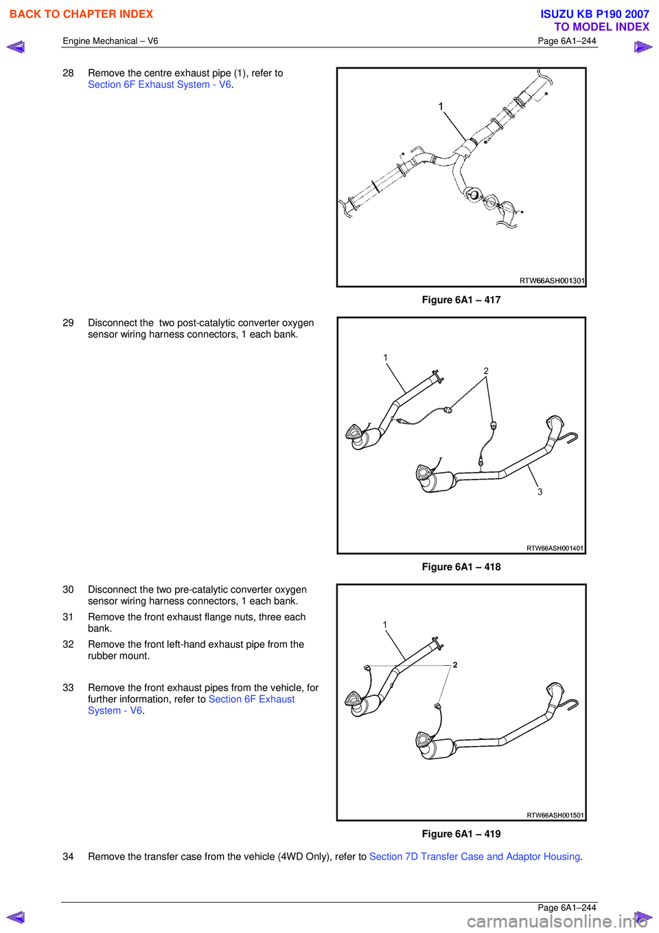
28 Remove the centre exhaust pipe (1), refer to
Section 6F Exhaust System - V6 .
Figure 6A1 – 417
29 Disconnect the two post-catalytic converter oxygen sensor wiring harness connectors, 1 each bank.
Figure 6A1 – 418
30 Disconnect the two pre-catalytic converter oxygen sensor wiring harness connectors, 1 each bank.
31 Remove the front exhaust flange nuts, three each bank.
32 Remove the front left-hand exhaust pipe from the rubber mount.
33 Remove the front exhaust pipes from the vehicle, for further information, refer to Section 6F Exhaust
System - V6 .
Figure 6A1 – 419
34 Remove the transfer case from t he vehicle (4WD Only), refer to Section 7D Transfer Case and Adaptor Housing .
BACK TO CHAPTER INDEX
TO MODEL INDEX
ISUZU KB P190 2007
Page 3065 of 6020
Engine Mechanical – V6 Page 6A1–288
Page 6A1–288
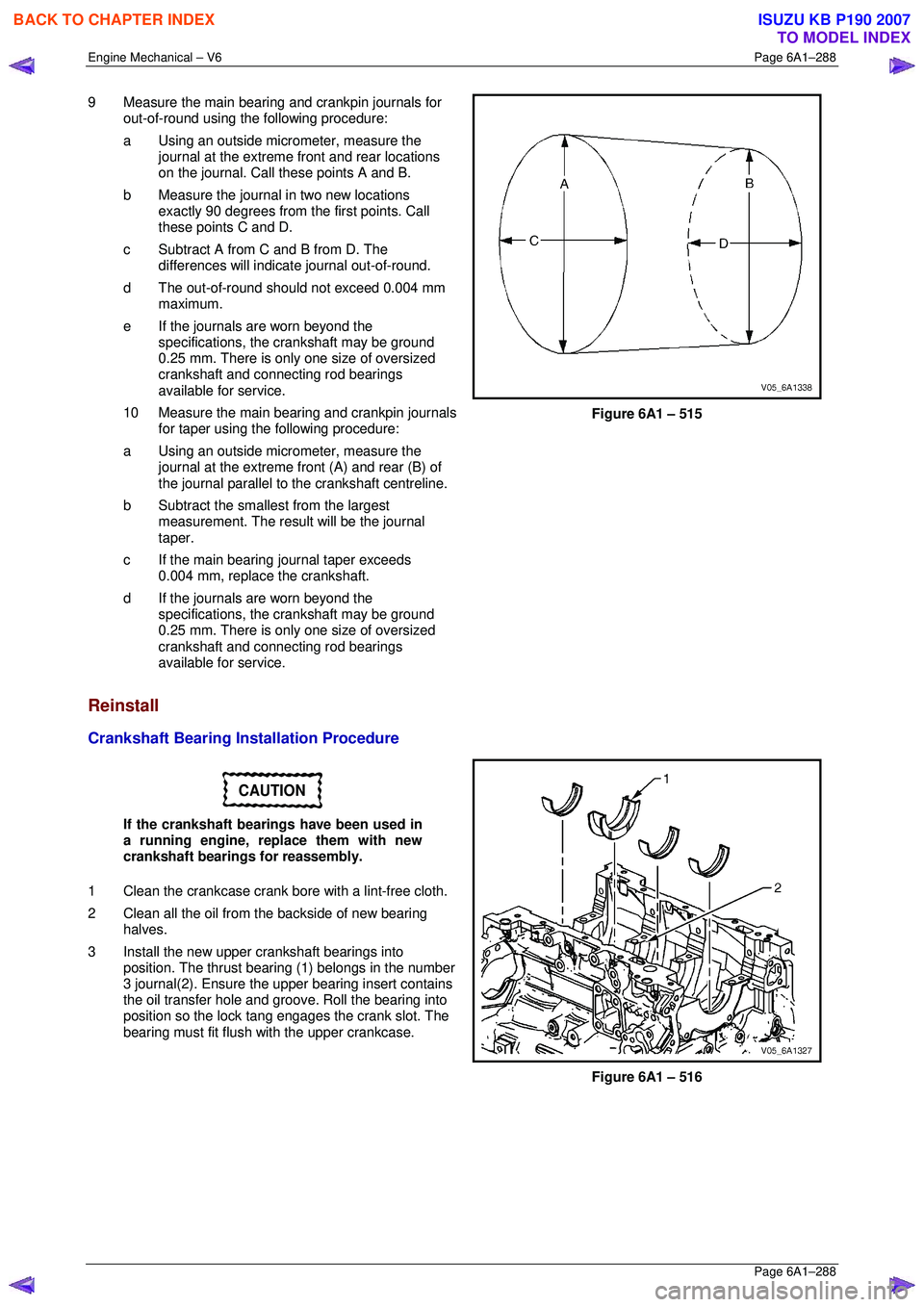
9 Measure the main bearing and crankpin journals for
out-of-round using the following procedure:
a Using an outside micr ometer, measure the
journal at the extreme front and rear locations
on the journal. Call these points A and B.
b Measure the journal in two new locations exactly 90 degrees from the first points. Call
these points C and D.
c Subtract A from C and B from D. The differences will indicate journal out-of-round.
d The out-of-round shoul d not exceed 0.004 mm
maximum.
e If the journals are worn beyond the specifications, the crankshaft may be ground
0.25 mm. There is only one size of oversized
crankshaft and connecting rod bearings
available for service.
10 Measure the main bearing and crankpin journals for taper using the following procedure:
a Using an outside micr ometer, measure the
journal at the extreme fr ont (A) and rear (B) of
the journal parallel to t he crankshaft centreline.
b Subtract the smallest from the largest measurement. The result will be the journal
taper.
c If the main bearing journal taper exceeds 0.004 mm, replace the crankshaft.
d If the journals are worn beyond the specifications, the crankshaft may be ground
0.25 mm. There is only one size of oversized
crankshaft and connecting rod bearings
available for service.
Figure 6A1 – 515
Reinstall
Crankshaft Bearing Installation Procedure
CAUTION
If the crankshaft bearings have been used in
a running engine, replace them with new
crankshaft bearings for reassembly.
1 Clean the crankcase crank bore with a lint-free cloth.
2 Clean all the oil from the backside of new bearing halves.
3 Install the new upper crankshaft bearings into position. The thrust beari ng (1) belongs in the number
3 journal(2). Ensure the upper bearing insert contains
the oil transfer hole and groove. Roll the bearing into
position so the lock tang engages the crank slot. The
bearing must fit flush with the upper crankcase.
Figure 6A1 – 516
BACK TO CHAPTER INDEX
TO MODEL INDEX
ISUZU KB P190 2007