2007 ISUZU KB P190 transfer case
[x] Cancel search: transfer casePage 3576 of 6020
Engine Management – V6 – Service Operations Page 6C1-3–52
Oil Fouled (3)
W et, oily deposits with minor electrode wear possibly due to oil leaking past worn piston rings.
Breaking in a new or recently overhauled engine before the rings are fully seated may also result in this condition.
Deposit Fouling A (4)
Red brown, yellow and white coloured coatings on the insulator tip which are by-products of combustion. They come
from fuel and lubricating oil which generally contain additives. Most powdery deposits have no adverse effect on spark
plug operation, however, they may cause intermittent missing under severe operating conditions.
Deposit Fouling B (5)
Deposits similar to those identified in deposit fouling A (4). These are also by-products of combustion from fuel and
lubricating oil. Excessive valve stem clearances and / or defective intake valve seals allow too much oil to enter the
combustion chamber. The deposits will accumulate on the portion of the spark plug that projects into the chamber and
will be heaviest on the side facing the intake valve. If this condition is only detected in one or two cylinders, check the
valve stem seals.
Deposit Fouling C (6)
Most powdery deposits identified in deposit fouling A (4) have no adverse effect on the operation of the spark plug as
long as they remain powdery.
Under certain conditions of operation however, these deposits melt and form a shiny glaze coating on the insulator.
W hen hot, this acts as a good electrical conductor allowing the current to flow along the deposit instead of sparking
across the gap.
Detonation (7)
Commonly referred to as engine knock or pinging, detonation causes severe shocks inside the combustion chamber
causing damage to parts.
Pre-ignition (8)
Burnt or blistered insulator tip and badly eroded electrodes probably due to the excessive heat.
This is often caused by a cooling system blockage, sticking valves, improperly installed spark plugs or plugs that are the
wrong heat rating (too hot).
Sustained high speed with a heavy load can produce temperatures high enough to cause pre-ignition.
Heat Shock Failure (9)
A rapid increase in spark plug tip temperature under severe operating conditions can cause heat shock and result in
fractured insulators. This is a common cause of broken and cracked insulator tips.
Insufficient Installation Torque (10)
Poor contact between the spark plug and the cylinder head seat.
The lack of proper heat transfer that results from poor seat contact causes overheating of the spark plug. In many cases,
severe damage occurs. Dirty threads in the cylinder head can cause the plug to seize before it is seated.
Ensure the cylinder head and spark plug threads are free of deposits, burrs and scale before installation.
BACK TO CHAPTER INDEX
TO MODEL INDEX
ISUZU KB P190 2007
Page 3759 of 6020
SECTION 7
TRANSMISSION
TA BLE OF CONTENTS
TRANSMISSION 7
A UTO MATIC TR ANS MISSIO N 4 L 60 E
TRANSMISSION AW30-40LE MODEL
TRANSMISSION JR405E MODEL
MANUAL TRANSMISSION MSG MUA MUX MODELS
CLUTCH
TRANSFER CASE
TO MODEL INDEX
BACK TO MAIN INDEX
ISUZU KB P190 2007
Page 3916 of 6020
Automatic Transmission – 4L60E – On-vehicle Servicing Page 7C4–3
1 General Information
This Section describes the removal and reinstallation procedures of the four speed 4L60E hydra-matic automatic
transmission as well as the service operations which can be performed with the transmission still fitted to the vehicle.
1.1 General Service Information
Description
The shift selector mechanism is linked to the transmission manual shaft with a selector cable. A heat protector is fitted
over the neutral start and back-up switch and manual shaft select lever.
For rear wheel drive (RWD) vehicles an extension housing is fitted to the rear of the transmission case.
Four wheel drive (4W D) vehicles have an adaptor housing and transfer case fitted to the rear of the transmission case,
for description and service operation refer to 7D Transfer Case and Adaptor Housing.
The four speed 4L60E hydra-matic automatic transmission is fitted with a filler tube, a breather hose and a vent pipe for
hot fluid overflow.
The transmission fluid is driven through a cooler within the radiator via the cooler line/hose assemblies to maintain
normal operating temperature.
Service Information
Throughout the service operations within this
Section, when handling retaining clips, using
compressed air or cleaning fluids, wear safety
equipment to avoid personal injury.
Refer to 7C1 Automatic Transmission – 4L60E – General Information for the following:
• information relating to mechanical and electrical operations,
• abbreviations, transmission specifications, special tools and torque wrench specifications,
• servicing, cleaning and inspection procedure recommendations.
It is essential to read and understand the General Information, W arnings, Cautions and Service Notes contained in that
same Section, before any service operation is performed on the four speed 4L60E hydra-matic automatic transmission or
any associated components.
Failure to comply with the procedures and service notes can affect the reliable and efficient operation of this automatic
transmission.
1.2 WARNINGS, CAUTIONS and NOTES
This Section contains various W ARNINGS, CAUTIONS and NOTE statements that you must observe carefully to reduce
the risk of death or injury during service, repair procedures or vehicle operation. Incorrect service or repair procedures
may damage the vehicle or cause operational faults. W ARNINGS, CAUTION and NOTE statements are not exhaustive.
GM HOLDEN LTD can not possibly warn of all the potentially hazardous consequences of failure to follow these
instructions.
Definition of WARNING, CAUTION and NOTE Statements
Diagnosis and repair procedures in this Section contain both general and specific W ARNING, CAUTION and NOTE
statements. GM HOLDEN LTD is dedicated to the presentation of service information that helps the technician to
diagnose and repair the systems necessary for proper operation of the vehicle. Certain procedures may present a hazard
to the technician if they are not followed in the recommended manner. W ARNING, CAUTION and NOTE statements are
designed to help prevent these hazards from occurring, but not all hazards can be foreseen.
BACK TO CHAPTER INDEX
TO MODEL INDEX
ISUZU KB P190 2007
Page 3931 of 6020
Automatic Transmission – 4L60E – On-vehicle Servicing Page 7C4–18
Ensure the four wheels are off the ground
before performing the starting test.
4 W ith the ignition switched to the ON position, check if the engine can only be started in the Park and Neutral shift selector positions and ensure the back-up lamps illuminate when Reverse is selected. A further minor adjustment
may be required to achieve this state.
NOTE
To gain access to the rear attaching screw (11) it
will be necessary to remove the connector.
5 After the switch has been adjusted, tighten the rear attaching screw (11) to the correct torque specification. Neutral start and back-up lamp switch
attaching screw torque specification .................. 25.0 Nm
6 Reinstall the connector and the CPA securing pin.
7 Remove the switch front attaching screw (1).
8 Install the heat shield (3) and tighten the attaching screws (1 and 2) to the correct torque specification.
Heat shield front attaching screw
torque specification ............................................ 25.0 Nm
Heat shield rear attaching screw torque specification ..............................................9.0 Nm
9 Lower the vehicle to the ground and re-check the operation of the neutral start and back-up lamp switch. The vehicle must start only with the shift selector in the Park or Neutral positions and the back-up lamps should only
illuminate when Reverse is selected.
3.5 Vehicle Speed Sensor
NOTE
For the speed sensor fitted to four wheel drive
vehicles (4WD), refer to 7D Transfer Case and
Adaptor Housing.
Remove
1 Raise the vehicle and support in a safe manner, refer
to 0A General Information for the location of support
points.
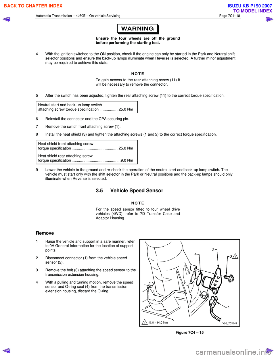
2 Disconnect connector (1) from the vehicle speed sensor (2).
3 Remove the bolt (3) attaching the speed sensor to the transmission extension housing.
4 With a pulling and turning motion, remove the speed sensor and O-ring seal (4) from the transmission
extension housing, discard the O-ring.
Figure 7C4 – 15
BACK TO CHAPTER INDEX
TO MODEL INDEX
ISUZU KB P190 2007
Page 3937 of 6020
Automatic Transmission – 4L60E – On-vehicle Servicing Page 7C4–24
7 Lubricate the outside of a new bush with automatic
transmission fluid to reduce the chance of material
pick-up.
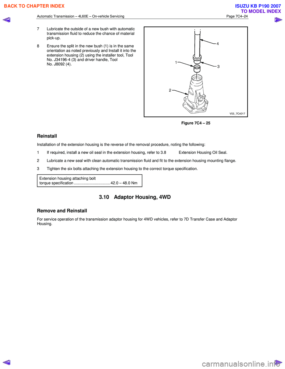
8 Ensure the split in the new bush (1) is in the same orientation as noted previously and Install it into the
extension housing (2) using the installer tool, Tool
No. J34196-4 (3) and driver handle, Tool
No. J8092 (4).
Figure 7C4 – 25
Reinstall
Installation of the extension housing is the reverse of the removal procedure, noting the following:
1 If required, install a new oil seal in the extension housing, refer to 3.8 Extension Housing Oil Seal.
2 Lubricate a new seal with clean automatic transmission fluid and fit to the extension housing mounting flange.
3 Tighten the six bolts attaching the extension housing to the correct torque specification.
Extension housing attaching bolt
torque specification ................................. 42.0 – 48.0 Nm
3.10 Adaptor Housing, 4WD
Remove and Reinstall
For service operation of the transmission adaptor housing for 4W D vehicles, refer to 7D Transfer Case and Adaptor
Housing.
BACK TO CHAPTER INDEX
TO MODEL INDEX
ISUZU KB P190 2007
Page 3956 of 6020
Automatic Transmission – 4L60E – On-vehicle Servicing Page 7C4–43
If the verifier disc does not clip into place, the
quick-connect fitting is not engaged, rectify
as required.
10 As a security check, push and clip each verification disc into place over the quick-connect fittings. If difficulty is experienced, repeat the installation process until the verification disc can be clipped into place over the radiator
quick-connect fitting.
11 Snap the outlet cooler line (4) in the clip (5) of the radiator fan shroud.
12 Ensure the routeing of the cooler lines is correct and there is no fouling of the lines.
13 Tighten the screw attaching the cooler lines bracket to the correct torque specifications.
Transmission cooler lines bracket
attaching screw torque specification .................. 23.0 Nm
14 If required, top up the transmission fluid level (cold).
15 Start the engine and check for any fluid leak at the fittings. If a leak is found, stop the engine and rectify the leak.
16 Check and top up the transmission fluid to the correct level as required, refer to 2.1 Transmission Fluid.
3.18 Transmission Assembly
Remove
Disconnection of the battery affects certain
vehicle electronic systems. Refer to 6D1-3
Battery, before disconnecting the battery.
1 Disconnect the battery ground lead.
2 Raise the vehicle and support in a safe manner, refer to 0A General Information for the location of support points.
3 Remove the heat shield from the neutral start and back-up lamp switch, gently prise the selector cable from the transmission external manual shaft linkage and remove the selector cable from the bracket, refer to
3.3 Selector Cable Assembly.
4 Disconnect the harness connectors from the following:
a Vehicle speed sensor, refer to 3.5 Vehicle Speed Sensor.
b Neutral start and back-up switch, refer to 3.4 Neutral Start and Back-up Lamp Switch.
c For the following on four wheel drive vehicles (4W D), refer to 7D Transfer Case and Adaptor Housing:
• neutral switch,
• 2WD – 4WD shift actuator switch,
• speed sensor.
NOTE
If the battery is connected, avoid turning the
ignition switch to the ON position, as the transfer
case control module (TTCM) must first be
removed (memory to be cleared as Check 4W D
Indicator will light).
5 Remove the following components: a Front and centre exhaust assemblies, refer to 6F Exhaust System.
BACK TO CHAPTER INDEX
TO MODEL INDEX
ISUZU KB P190 2007
Page 3957 of 6020
Automatic Transmission – 4L60E – On-vehicle Servicing Page 7C4–44
b Starter motor, refer to 6D1-2 Starting System.
b Rear propeller shaft and for 4WD front propeller shaft, refer to 4A Propeller Shaft.
6 On 4WD vehicle, disconnect the harness two clips from the upper side of the transfer case.
7 From within the starter motor access hole, remove the three bolts (2) attaching the torque converter to the flexplate and discard, refer to Figure 7C4 – 62.
8 Remove the transmission support, refer to 3.7 Transmission Support and Mount.
9 Disconnect the fuel and EVAP pipes three brackets and clips, refer to 6C Fuel System – V6.
Before lowering the transmission take care of
the following:
• Do not strain the harness and connector
as the connector pins could be
permanently damaged.
• Ensure the inlet manifold does not hit the
firewall.
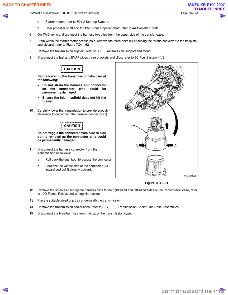
10 Carefully lower the transmission to provide enough clearance to disconnect the harness connector (1).
Do not wiggle the connector from side to side
during removal as the connector pins could
be permanently damaged.
11 Disconnect the harness connector from the transmission as follows:
a Roll back the dust boot to access the connector.
b Squeeze the widest side of the connector (A) inward and pull it directly upward.
Figure 7C4 – 61
12 Remove the screws attaching the harness clips to the right-hand and left-hand sides of the transmission case, refer to 12O Fuses, Relays and W iring Harnesses.
13 Place a suitable sized drip tray underneath the transmission.
14 Remove the transmission cooler lines, refer to 3.17 Transmission Cooler Line/Hose Assemblies.
15 Disconnect the breather hose from the top of the transmission case.
BACK TO CHAPTER INDEX
TO MODEL INDEX
ISUZU KB P190 2007
Page 3958 of 6020
Automatic Transmission – 4L60E – On-vehicle Servicing Page 7C4–45
Support the transmission when removing the
attaching bolts to avoid damage to the torque
converter and flexplate. Do not have the
transmission hanging.
NOTE
The bolts attaching the torque converter housing
are facing forward except for the bolt in position ℑ
which is facing rearward.
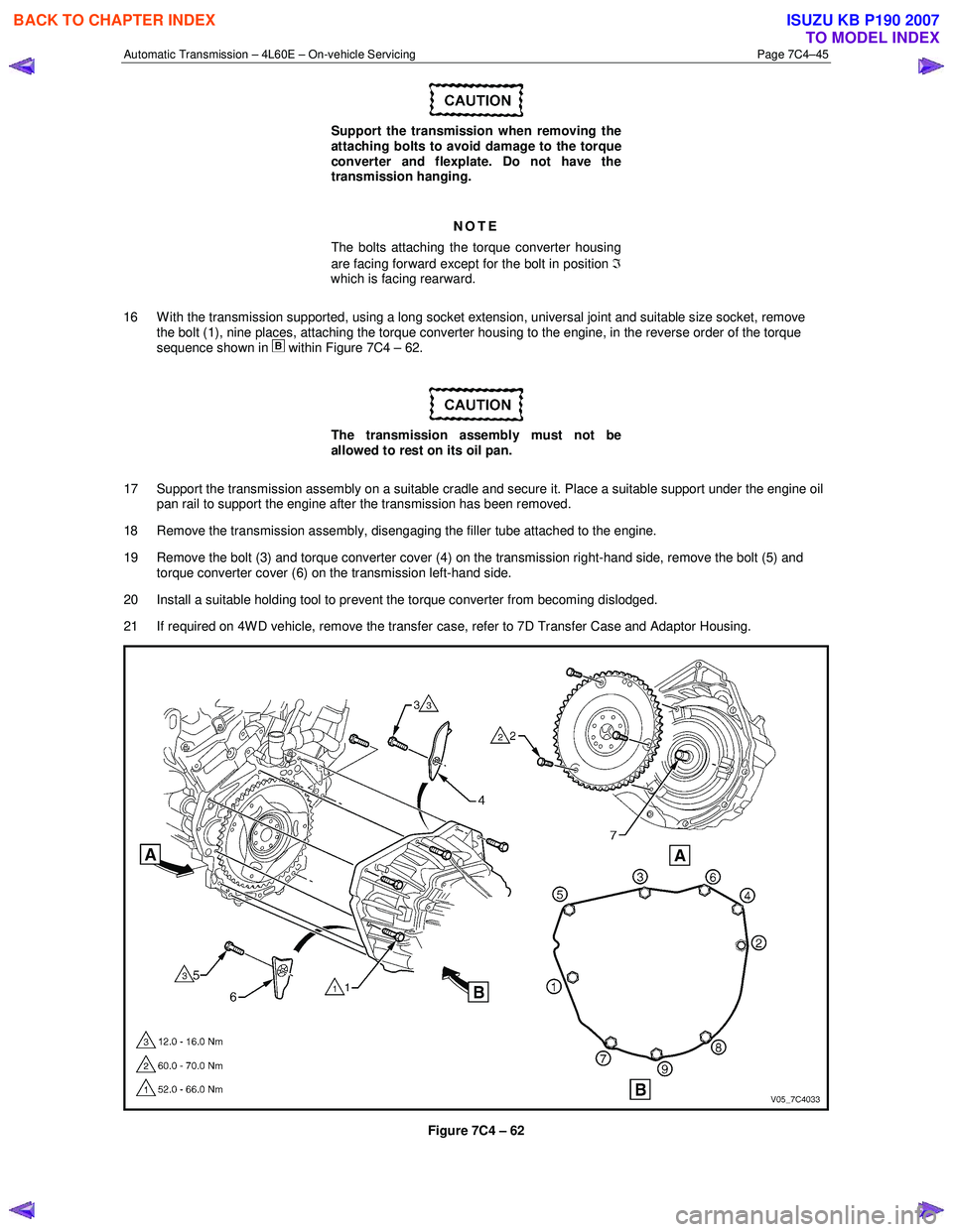
16 W ith the transmission supported, using a long socket extension, universal joint and suitable size socket, remove the bolt (1), nine places, attaching the torque converter housing to the engine, in the reverse order of the torque
sequence shown in
within Figure 7C4 – 62.
The transmission assembly must not be
allowed to rest on its oil pan.
17 Support the transmission assembly on a suitable cradle and secure it. Place a suitable support under the engine oil pan rail to support the engine after the transmission has been removed.
18 Remove the transmission assembly, disengaging the filler tube attached to the engine.
19 Remove the bolt (3) and torque converter cover (4) on the transmission right-hand side, remove the bolt (5) and torque converter cover (6) on the transmission left-hand side.
20 Install a suitable holding tool to prevent the torque converter from becoming dislodged.
21 If required on 4W D vehicle, remove the transfer case, refer to 7D Transfer Case and Adaptor Housing.
Figure 7C4 – 62
BACK TO CHAPTER INDEX
TO MODEL INDEX
ISUZU KB P190 2007