2007 ISUZU KB P190 battery location
[x] Cancel search: battery locationPage 2302 of 6020
6E–132 ENGINE DRIVEABILITY AND EMISSIONS
terminals, and poor terminal-to-wire connection.
• Damaged harness - Inspect the wiring harness for damage, short to ground, short to battery positive,
and open circuit. If the harness appears to be OK, observe the IAT display on the Tech 2 while moving
connectors and wiring harnesses related to the IAT
sensor. A change in the IAT display will indicate the
location of the fault.
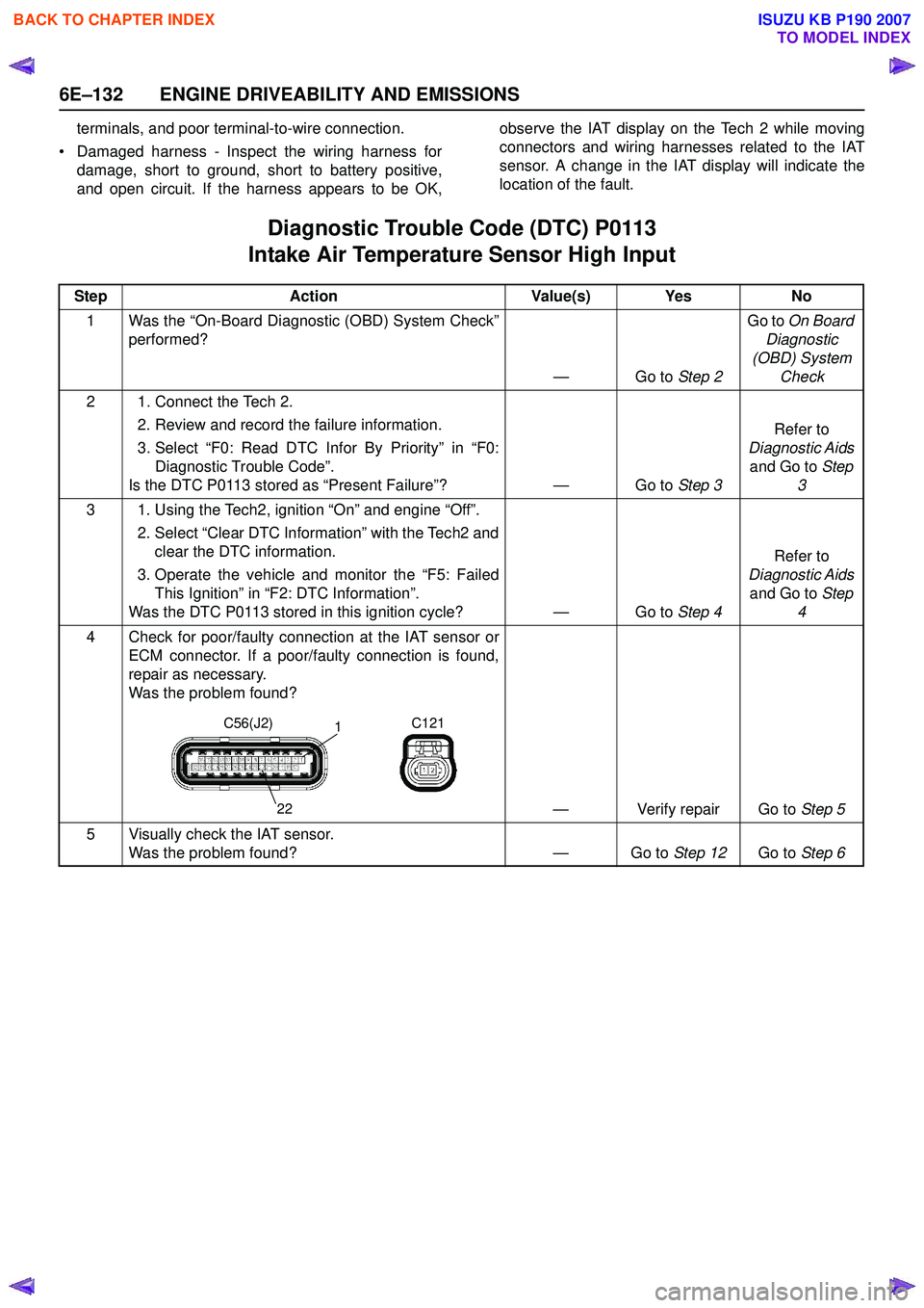
Diagnostic Trouble Code (DTC) P0113
Intake Air Temperature Sensor High Input
Step Action Value(s) Yes No
1 Was the “On-Board Diagnostic (OBD) System Check” performed?
—Go to Step 2Go to
On Board
Diagnostic
(OBD) System Check
2 1. Connect the Tech 2. 2. Review and record the failure information.
3. Select “F0: Read DTC Infor By Priority” in “F0: Diagnostic Trouble Code”.
Is the DTC P0113 stored as “Present Failure”? — Go to Step 3Refer to
Diagnostic Aids and Go to Step
3
3 1. Using the Tech2, ignition “On” and engine “Off”. 2. Select “Clear DTC Information” with the Tech2 andclear the DTC information.
3. Operate the vehicle and monitor the “F5: Failed This Ignition” in “F2: DTC Information”.
Was the DTC P0113 stored in this ignition cycle? — Go to Step 4Refer to
Diagnostic Aids and Go to Step
4
4 Check for poor/faulty connection at the IAT sensor or ECM connector. If a poor/faulty connection is found,
repair as necessary.
Was the problem found?
— Verify repair Go to Step 5
5 Visually check the IAT sensor. Was the problem found? — Go to Step 12Go to Step 6
C56(J2) C121
1
22
BACK TO CHAPTER INDEX
TO MODEL INDEX
ISUZU KB P190 2007
Page 2306 of 6020
6E–136 ENGINE DRIVEABILITY AND EMISSIONS
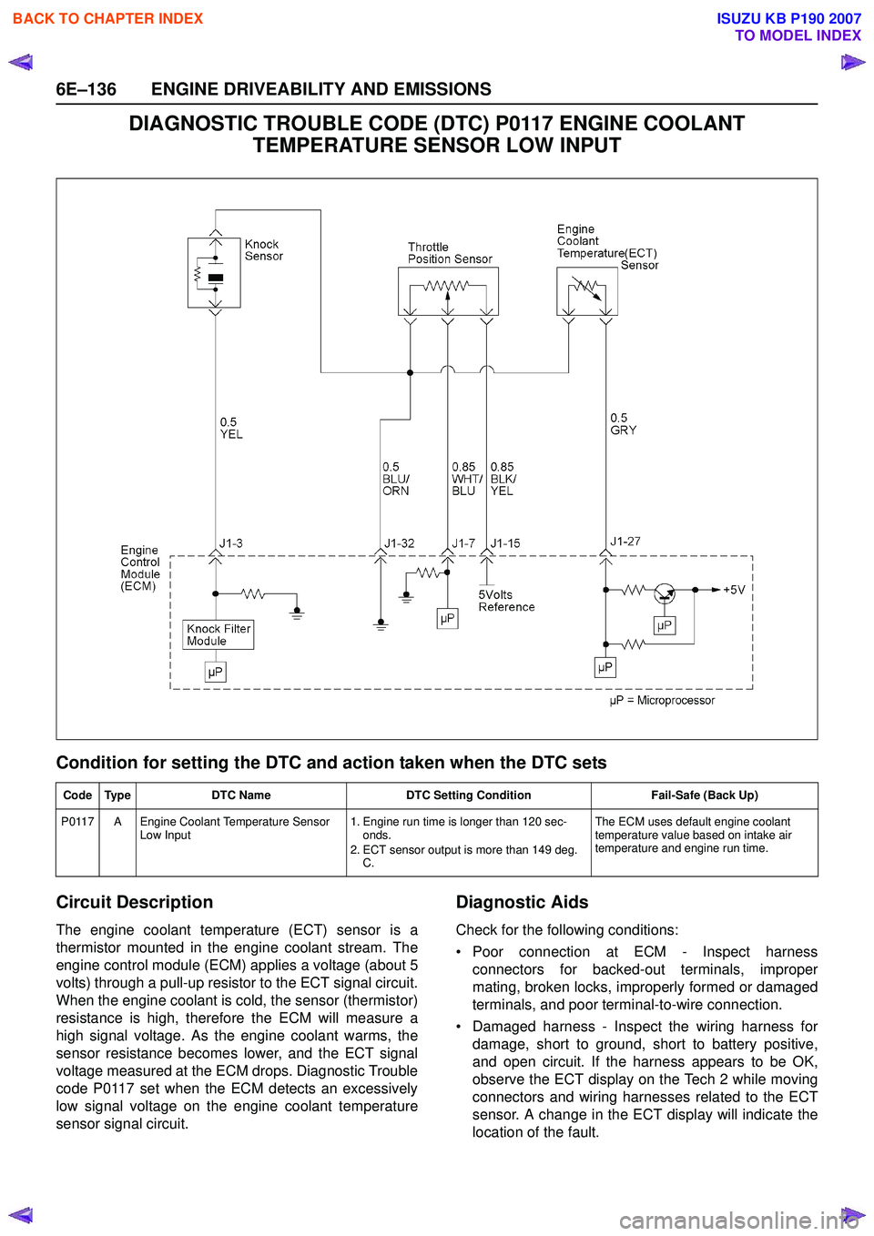
DIAGNOSTIC TROUBLE CODE (DTC) P0117 ENGINE COOLANT TEMPERATURE SENSOR LOW INPUT
Condition for setting the DTC and action taken when the DTC sets
Circuit Description
The engine coolant temperature (ECT) sensor is a
thermistor mounted in the engine coolant stream. The
engine control module (ECM) applies a voltage (about 5
volts) through a pull-up resistor to the ECT signal circuit.
When the engine coolant is cold, the sensor (thermistor)
resistance is high, therefore the ECM will measure a
high signal voltage. As the engine coolant warms, the
sensor resistance becomes lower, and the ECT signal
voltage measured at the ECM drops. Diagnostic Trouble
code P0117 set when the ECM detects an excessively
low signal voltage on the engine coolant temperature
sensor signal circuit.
Diagnostic Aids
Check for the following conditions:
• Poor connection at ECM - Inspect harness connectors for backed-out terminals, improper
mating, broken locks, improperly formed or damaged
terminals, and poor terminal-to-wire connection.
• Damaged harness - Inspect the wiring harness for damage, short to ground, short to battery positive,
and open circuit. If the harness appears to be OK,
observe the ECT display on the Tech 2 while moving
connectors and wiring harnesses related to the ECT
sensor. A change in the ECT display will indicate the
location of the fault.
Code Type DTC Name DTC Setting Condition Fail-Safe (Back Up)
P0117 A Engine Coolant Temperature Sensor Low Input 1. Engine run time is longer than 120 sec-
onds.
2. ECT sensor output is more than 149 deg. C. The ECM uses default engine coolant
temperature value based on intake air
temperature and engine run time.
BACK TO CHAPTER INDEX
TO MODEL INDEX
ISUZU KB P190 2007
Page 2309 of 6020
ENGINE DRIVEABILITY AND EMISSIONS 6E–139
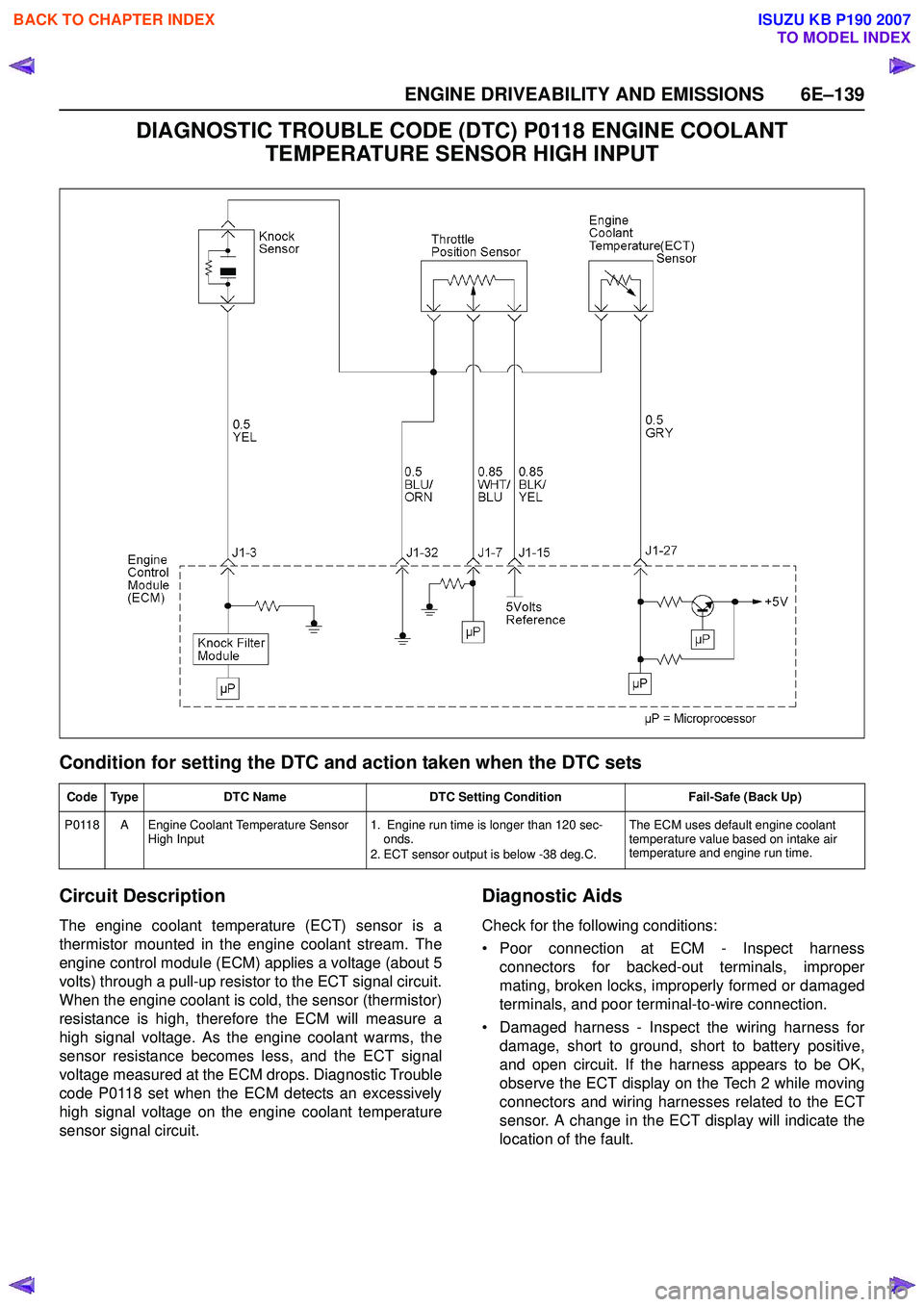
DIAGNOSTIC TROUBLE CODE (DTC) P0118 ENGINE COOLANT TEMPERATURE SENSOR HIGH INPUT
Condition for setting the DTC and action taken when the DTC sets
Circuit Description
The engine coolant temperature (ECT) sensor is a
thermistor mounted in the engine coolant stream. The
engine control module (ECM) applies a voltage (about 5
volts) through a pull-up resistor to the ECT signal circuit.
When the engine coolant is cold, the sensor (thermistor)
resistance is high, therefore the ECM will measure a
high signal voltage. As the engine coolant warms, the
sensor resistance becomes less, and the ECT signal
voltage measured at the ECM drops. Diagnostic Trouble
code P0118 set when the ECM detects an excessively
high signal voltage on the engine coolant temperature
sensor signal circuit.
Diagnostic Aids
Check for the following conditions:
• Poor connection at ECM - Inspect harness connectors for backed-out terminals, improper
mating, broken locks, improperly formed or damaged
terminals, and poor terminal-to-wire connection.
• Damaged harness - Inspect the wiring harness for damage, short to ground, short to battery positive,
and open circuit. If the harness appears to be OK,
observe the ECT display on the Tech 2 while moving
connectors and wiring harnesses related to the ECT
sensor. A change in the ECT display will indicate the
location of the fault.
Code Type DTC Name DTC Setting Condition Fail-Safe (Back Up)
P0118 A Engine Coolant Temperature Sensor High Input 1. Engine run time is longer than 120 sec-
onds.
2. ECT sensor output is below -38 deg.C. The ECM uses default engine coolant
temperature value based on intake air
temperature and engine run time.
BACK TO CHAPTER INDEX
TO MODEL INDEX
ISUZU KB P190 2007
Page 2313 of 6020
ENGINE DRIVEABILITY AND EMISSIONS 6E–143
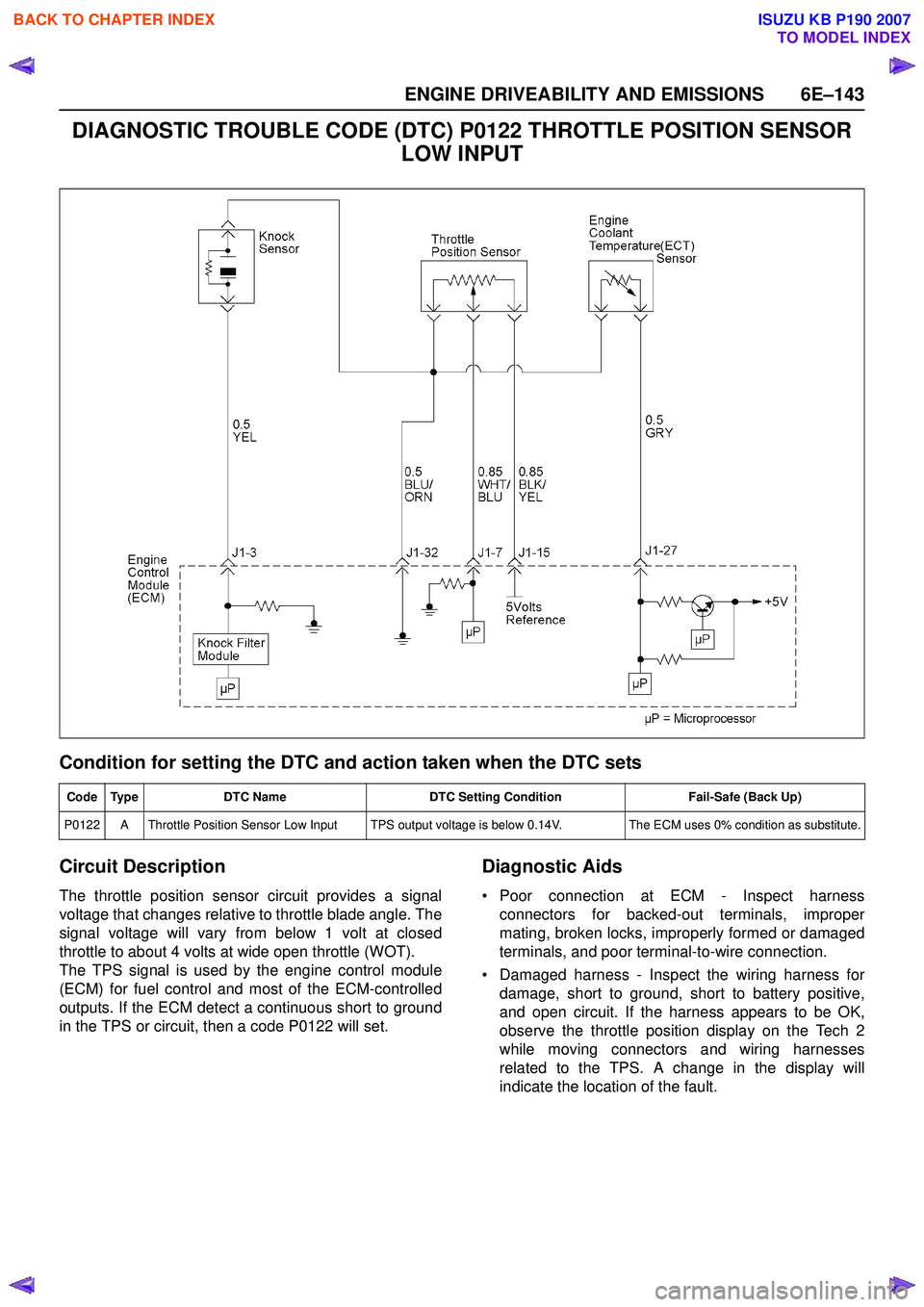
DIAGNOSTIC TROUBLE CODE (DTC) P0122 THROTTLE POSITION SENSOR LOW INPUT
Condition for setting the DTC and action taken when the DTC sets
Circuit Description
The throttle position sensor circuit provides a signal
voltage that changes relative to throttle blade angle. The
signal voltage will vary from below 1 volt at closed
throttle to about 4 volts at wide open throttle (WOT).
The TPS signal is used by the engine control module
(ECM) for fuel control and most of the ECM-controlled
outputs. If the ECM detect a continuous short to ground
in the TPS or circuit, then a code P0122 will set.
Diagnostic Aids
• Poor connection at ECM - Inspect harness connectors for backed-out terminals, improper
mating, broken locks, improperly formed or damaged
terminals, and poor terminal-to-wire connection.
• Damaged harness - Inspect the wiring harness for damage, short to ground, short to battery positive,
and open circuit. If the harness appears to be OK,
observe the throttle position display on the Tech 2
while moving connectors and wiring harnesses
related to the TPS. A change in the display will
indicate the location of the fault.
Code Type DTC Name DTC Setting Condition Fail-Safe (Back Up)
P0122 A Throttle Position Sensor Low Input TPS output voltage is below 0.14V. The ECM uses 0% condition as substitute.
BACK TO CHAPTER INDEX
TO MODEL INDEX
ISUZU KB P190 2007
Page 2317 of 6020
ENGINE DRIVEABILITY AND EMISSIONS 6E–147
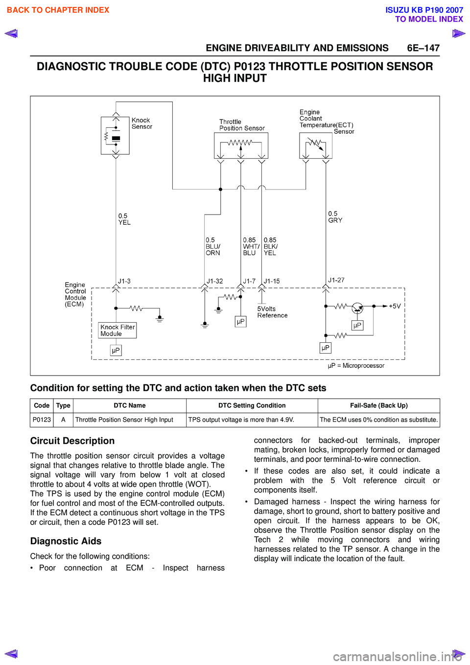
DIAGNOSTIC TROUBLE CODE (DTC) P0123 THROTTLE POSITION SENSOR HIGH INPUT
Condition for setting the DTC and action taken when the DTC sets
Circuit Description
The throttle position sensor circuit provides a voltage
signal that changes relative to throttle blade angle. The
signal voltage will vary from below 1 volt at closed
throttle to about 4 volts at wide open throttle (WOT).
The TPS is used by the engine control module (ECM)
for fuel control and most of the ECM-controlled outputs.
If the ECM detect a continuous short voltage in the TPS
or circuit, then a code P0123 will set.
Diagnostic Aids
Check for the following conditions:
• Poor connection at ECM - Inspect harness connectors for backed-out terminals, improper
mating, broken locks, improperly formed or damaged
terminals, and poor terminal-to-wire connection.
• If these codes are also set, it could indicate a problem with the 5 Volt reference circuit or
components itself.
• Damaged harness - Inspect the wiring harness for damage, short to ground, short to battery positive and
open circuit. If the harness appears to be OK,
observe the Throttle Position sensor display on the
Tech 2 while moving connectors and wiring
harnesses related to the TP sensor. A change in the
display will indicate the location of the fault.
Code Type DTC Name DTC Setting Condition Fail-Safe (Back Up)
P0123 A Throttle Position Sensor High Input TPS output voltage is more than 4.9V. The ECM uses 0% condition as substitute.
BACK TO CHAPTER INDEX
TO MODEL INDEX
ISUZU KB P190 2007
Page 2351 of 6020
ENGINE DRIVEABILITY AND EMISSIONS 6E–181
Diagnostic Aids
An intermittent may be caused by a poor connection,
rubbed-through wire insulation or a wire broken inside
the insulation. Check for:
• Poor connection - Inspect the ECM harness and connectors for improper mating, broken locks,
improperly formed or damaged terminals, and poor
terminal-to-wire connection. • Damaged harness - Inspect the wiring harness for
damage; shorts to ground, shorts to battery positive
and open circuits. If the harness appears to be OK,
disconnect the ECM, turn the ignition on and observe
a voltmeter connected to the 58X reference circuit at
the ECM harness connector while moving connectors
and wiring harnesses related to the ECM. A change
in voltage will indicate the location of the fault.
Diagnostic Trouble Code (DTC) P0336
Crankshaft Position Sensor Circuit Range/performance (58x)
Diagnostic Trouble Code (DTC) P0337
Crankshaft Position Sensor Circuit Low Input (58x)
Step Action Value(s) Yes No
1 Was the “On-Board Diagnostic (OBD) System Check” performed?
—Go to Step 2Go to
On Board
Diagnostic
(OBD) System Check
2 1. Connect the Tech 2. 2. Review and record the failure information.
3. Select “F0: Read DTC Infor By Priority” in “F0: Diagnostic Trouble Code”.
Is the DTC P0336 or P0337 stored as “Present
Failure”? — Go to Step 3Refer to
Diagnostic Aids and Go to Step
3
3 1. Using the Tech2, ignition “On” and engine “Off”. 2. Select “Clear DTC Information” with the Tech2 andclear the DTC information.
3. Operate the vehicle and monitor the “F5: Failed This Ignition” in “F2: DTC Information”.
Was the DTC P0336 or P0337 stored in this ignition
cycle? — Go to Step 4Refer to
Diagnostic Aids and Go to Step
4
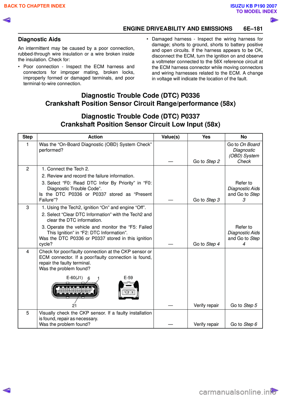
4 Check for poor/faulty connection at the CKP sensor or ECM connector. If a poor/faulty connection is found,
repair the faulty terminal.
Was the problem found?
— Verify repair Go to Step 5
5 Visually check the CKP sensor. If a faulty installation i s f o u n d , r e p a i r a s n e c e s s a r y.
Was the problem found? — Verify repair Go to Step 6
21
61
E-60(J1)
E-59
BACK TO CHAPTER INDEX
TO MODEL INDEX
ISUZU KB P190 2007
Page 2434 of 6020
6E–264 ENGINE DRIVEABILITY AND EMISSIONS
ON-VEHICLE SERVICE PROCEDURE
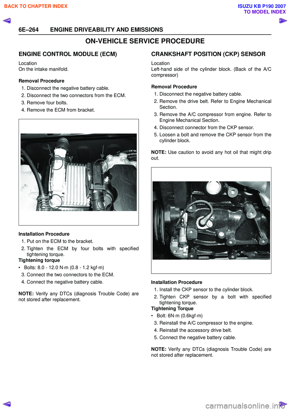
ENGINE CONTROL MODULE (ECM)
Location
On the intake manifold.
Removal Procedure 1. Disconnect the negative battery cable.
2. Disconnect the two connectors from the ECM.
3. Remove four bolts.
4. Remove the ECM from bracket.
Installation Procedure 1. Put on the ECM to the bracket.
2. Tighten the ECM by four bolts with specified tightening torque.
Tightening torque
• Bolts: 8.0 - 12.0 N·m (0.8 - 1.2 kgf·m) 3. Connect the two connectors to the ECM.
4. Connect the negative battery cable.
NOTE: Verify any DTCs (diagnosis Trouble Code) are
not stored after replacement.
CRANKSHAFT POSITION (CKP) SENSOR
Location
Left-hand side of the cylinder block. (Back of the A/C
compressor)
Removal Procedure 1. Disconnect the negative battery cable.
2. Remove the drive belt. Refer to Engine Mechanical Section.
3. Remove the A/C compressor from engine. Refer to Engine Mechanical Section.
4. Disconnect connector from the CKP sensor.
5. Loosen a bolt and remove the CKP sensor from the cylinder block.
NOTE: Use caution to avoid any hot oil that might drip
out.
Installation Procedure 1. Install the CKP sensor to the cylinder block.
2. Tighten CKP sensor by a bolt with specified tightening torque.
Tightening Torque
• Bolt: 6N·m (0.6kgf·m)
3. Reinstall the A/C compressor to the engine.
4. Reinstall the accessory drive belt.
5. Connect the negative battery cable.
NOTE: Verify any DTCs (diagnosis Trouble Code) are
not stored after replacement.
BACK TO CHAPTER INDEX
TO MODEL INDEX
ISUZU KB P190 2007
Page 2435 of 6020
ENGINE DRIVEABILITY AND EMISSIONS 6E–265
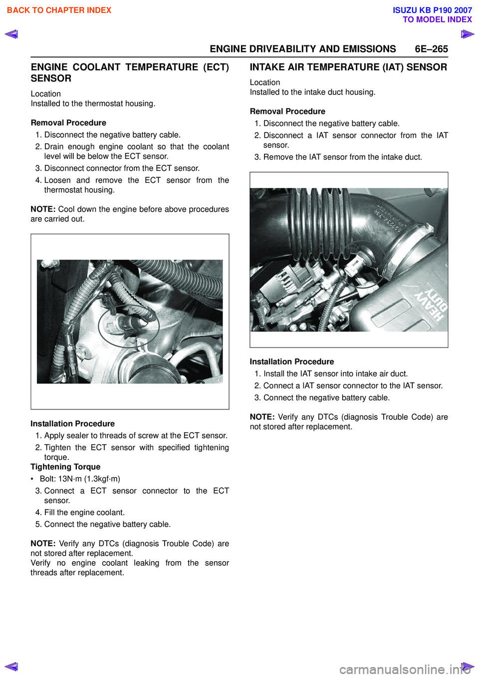
ENGINE COOLANT TEMPERATURE (ECT)
SENSOR
Location
Installed to the thermostat housing.
Removal Procedure 1. Disconnect the negative battery cable.
2. Drain enough engine coolant so that the coolant level will be below the ECT sensor.
3. Disconnect connector from the ECT sensor.
4. Loosen and remove the ECT sensor from the thermostat housing.
NOTE: Cool down the engine before above procedures
are carried out.
Installation Procedure
1. Apply sealer to threads of screw at the ECT sensor.
2. Tighten the ECT sensor with specified tightening torque.
Tightening Torque
• Bolt: 13N·m (1.3kgf·m)
3. Connect a ECT sensor connector to the ECT sensor.
4. Fill the engine coolant.
5. Connect the negative battery cable.
NOTE: Verify any DTCs (diagnosis Trouble Code) are
not stored after replacement.
Verify no engine coolant leaking from the sensor
threads after replacement.
INTAKE AIR TEMPERATURE (IAT) SENSOR
Location
Installed to the intake duct housing.
Removal Procedure 1. Disconnect the negative battery cable.
2. Disconnect a IAT sensor connector from the IAT sensor.
3. Remove the IAT sensor from the intake duct.
Installation Procedure 1. Install the IAT sensor into intake air duct.
2. Connect a IAT sensor connector to the IAT sensor.
3. Connect the negative battery cable.
NOTE: Verify any DTCs (diagnosis Trouble Code) are
not stored after replacement.
BACK TO CHAPTER INDEX
TO MODEL INDEX
ISUZU KB P190 2007