2007 ISUZU KB P190 battery location
[x] Cancel search: battery locationPage 2436 of 6020

6E–266 ENGINE DRIVEABILITY AND EMISSIONS
MANIFOLD ABSOLUTE PRESSURE (MAP)
SENSOR
Location
Installed on the intake manifold.
Removal Procedure 1. Disconenct the negative battery cable.
2. Disconnect a MAP sensor connector from the MAP sensor.
3. Loosen a bolt and remove the MAP sensor from the intake manifold.
4. Remove the MAP sensor from the bracket.
Installation Procedure 1. Tighten the MAP sensor by a bolt with specified tightening torque.
Tightening Torque
• Bolt: 8N·m (0.8kgf·m) 2. Connect a MAP sensor connector to the MAP sensor.
3. Connect the negative battery cable.
NOTE: Verify any DTCs (diagnosis Trouble Code) are
not stored after replacement.
THROTTLE POSITION SENSOR (TPS)
Location
Installed on the throttle body.
Removal Procedure 1. Disconnect the negative battery cable.
2. Disconnect the TPS connector.
3. Loosen two screws and remove TPS from the throttle body.
Installation Procedure 1. Temporary tighten the TPS by two screws.
2. Connect a TPS connectors to the TPS.
3. Connect the Tech2 to the vehicle.
4. Connect the negative battery cable.
5. Select "Data Display" with the Tech2.
6. Check the throttle position data and adjust the TPS position.
7. Tighten two screws.
NOTE: Verify any DTCs (diagnosis Trouble Code) are
not stored after replacement.
BACK TO CHAPTER INDEX
TO MODEL INDEX
ISUZU KB P190 2007
Page 2437 of 6020
ENGINE DRIVEABILITY AND EMISSIONS 6E–267
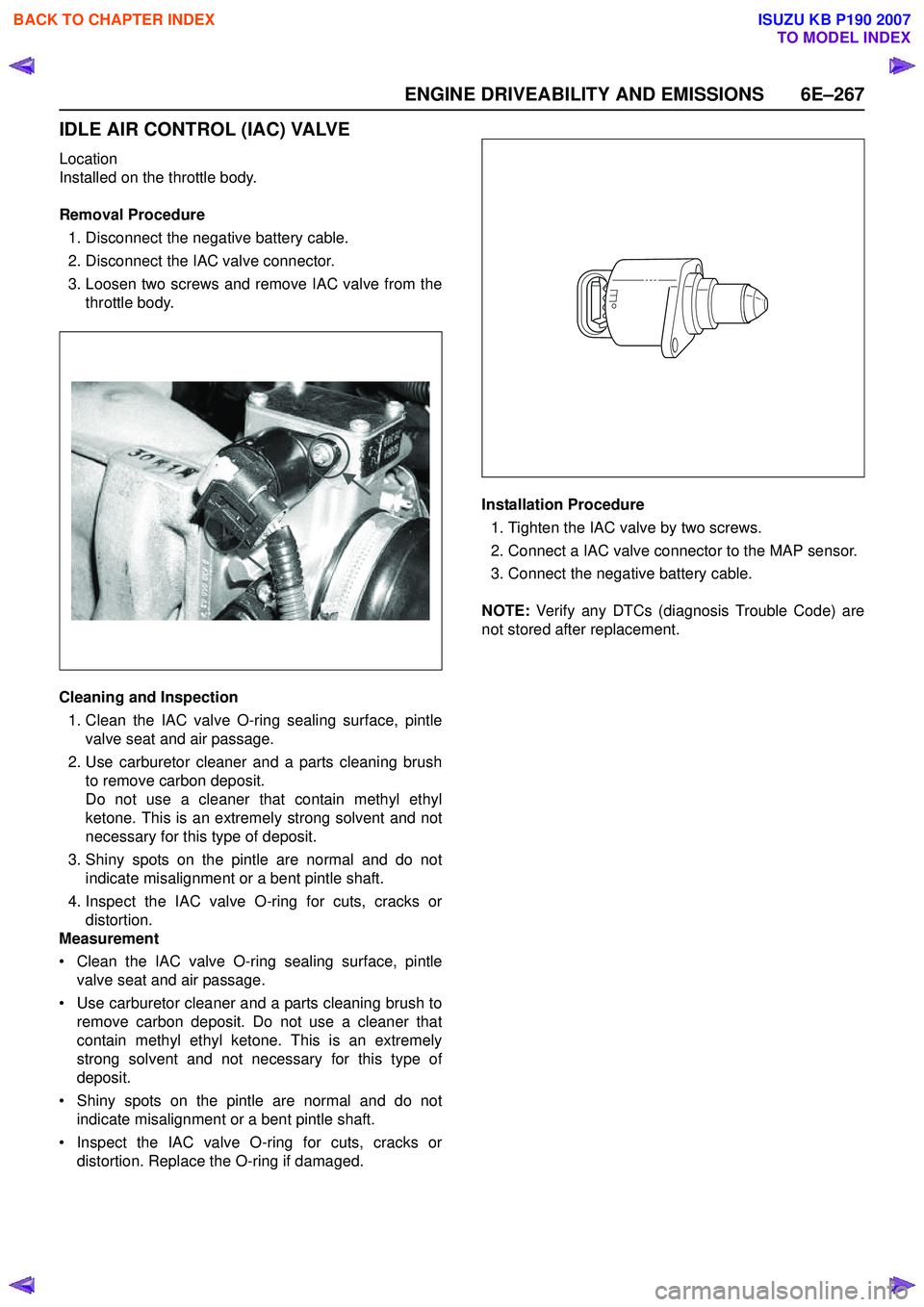
IDLE AIR CONTROL (IAC) VALVE
Location
Installed on the throttle body.
Removal Procedure 1. Disconnect the negative battery cable.
2. Disconnect the IAC valve connector.
3. Loosen two screws and remove IAC valve from the throttle body.
Cleaning and Inspection 1. Clean the IAC valve O-ring sealing surface, pintle valve seat and air passage.
2. Use carburetor cleaner and a parts cleaning brush to remove carbon deposit.
Do not use a cleaner that contain methyl ethyl
ketone. This is an extremely strong solvent and not
necessary for this type of deposit.
3. Shiny spots on the pintle are normal and do not indicate misalignment or a bent pintle shaft.
4. Inspect the IAC valve O-ring for cuts, cracks or distortion.
Measurement
• Clean the IAC valve O-ring sealing surface, pintle valve seat and air passage.
• Use carburetor cleaner and a parts cleaning brush to remove carbon deposit. Do not use a cleaner that
contain methyl ethyl ketone. This is an extremely
strong solvent and not necessary for this type of
deposit.
• Shiny spots on the pintle are normal and do not indicate misalignment or a bent pintle shaft.
• Inspect the IAC valve O-ring for cuts, cracks or distortion. Replace the O-ring if damaged. Installation Procedure
1. Tighten the IAC valve by two screws.
2. Connect a IAC valve connector to the MAP sensor.
3. Connect the negative battery cable.
NOTE: Verify any DTCs (diagnosis Trouble Code) are
not stored after replacement.
BACK TO CHAPTER INDEX
TO MODEL INDEX
ISUZU KB P190 2007
Page 2438 of 6020
6E–268 ENGINE DRIVEABILITY AND EMISSIONS
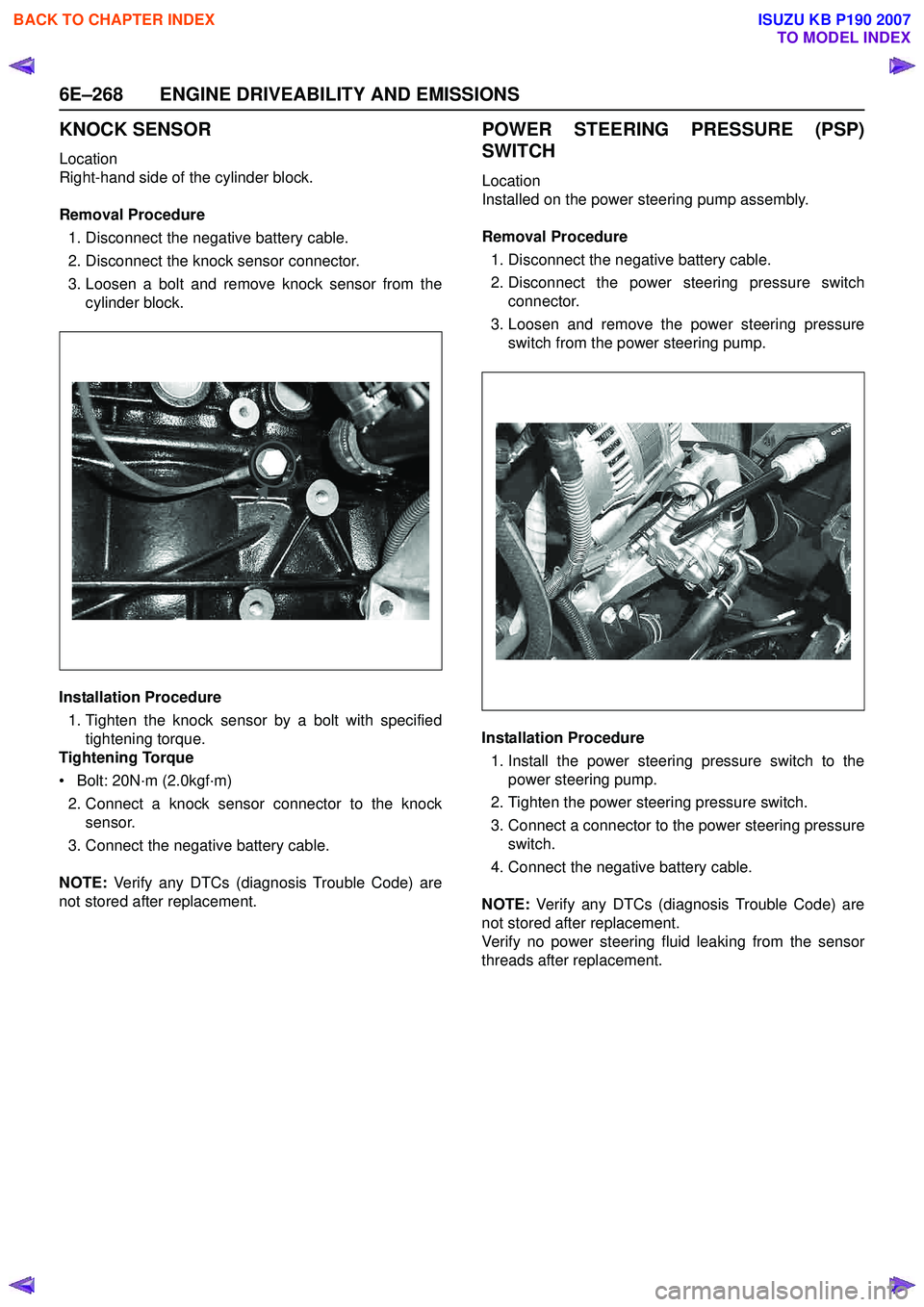
KNOCK SENSOR
Location
Right-hand side of the cylinder block.
Removal Procedure 1. Disconnect the negative battery cable.
2. Disconnect the knock sensor connector.
3. Loosen a bolt and remove knock sensor from the cylinder block.
Installation Procedure 1. Tighten the knock sensor by a bolt with specified tightening torque.
Tightening Torque
• Bolt: 20N·m (2.0kgf·m) 2. Connect a knock sensor connector to the knock sensor.
3. Connect the negative battery cable.
NOTE: Verify any DTCs (diagnosis Trouble Code) are
not stored after replacement.
POWER STEERING PRESSURE (PSP)
SWITCH
Location
Installed on the power steering pump assembly.
Removal Procedure 1. Disconnect the negative battery cable.
2. Disconnect the power steering pressure switch connector.
3. Loosen and remove the power steering pressure switch from the power steering pump.
Installation Procedure 1. Install the power steering pressure switch to the power steering pump.
2. Tighten the power steering pressure switch.
3. Connect a connector to the power steering pressure switch.
4. Connect the negative battery cable.
NOTE: Verify any DTCs (diagnosis Trouble Code) are
not stored after replacement.
Verify no power steering fluid leaking from the sensor
threads after replacement.
BACK TO CHAPTER INDEX
TO MODEL INDEX
ISUZU KB P190 2007
Page 2439 of 6020

ENGINE DRIVEABILITY AND EMISSIONS 6E–269
HEATED OXYGEN SENSOR (HO2S)
Location
Installed on the exhaust pipe.
Removal Procedure 1. Disconnect the negative battery cable.
2. Disconnect the O
2 sensor connector.
3. Loosen and remove the O
2 sensor from the exhaust
pipe.
Inspection
Inspect the louvered end of the sensor for grease, dirt,
excessive carbon build up or other contamination.
Installation Procedure
1. Install the O
2 sensor to the exhaust pipe.
2. Tighten the O
2 sensor with specified tightening
torque.
Tightening Torque
• Bolt: 42N·m (4.3kgf·m)
3. Connect a O
2 sensor connector to the O2 sensor.
4. Connect the negative battery cable.
NOTE: Verify any DTCs (diagnosis Trouble Code) are
not stored after replacement.
Verify no exhaust gas leaking from the sensor threads
after replacement.
EVAP CANISTER PURGE VALVE
SOLENOID
Location
On the intake manifold.
Removal Procedure 1. Disconenct the negative battery cable.
2. Disconnect a purge solenoid connector from the purge solenoid.
3. Disconnect two hoses from the purge solenoid valve.
4. Slide from the bracket and remove the purge solenoid.
Installation Procedure 1. Insert EVAP purge solenoid valve onto the bracket.
2. Connect two hoses to the purge solenoid valve.
3. Connect a purge solenoid connector to the purge solenoid.
4. Connect the negative battery cable.
NOTE: Verify any DTCs (diagnosis Trouble Code) are
not stored after replacement.
Verify proper connection of two hoses.
BACK TO CHAPTER INDEX
TO MODEL INDEX
ISUZU KB P190 2007
Page 2445 of 6020
ENGINE DRIVEABILITY AND EMISSIONS 6E–275
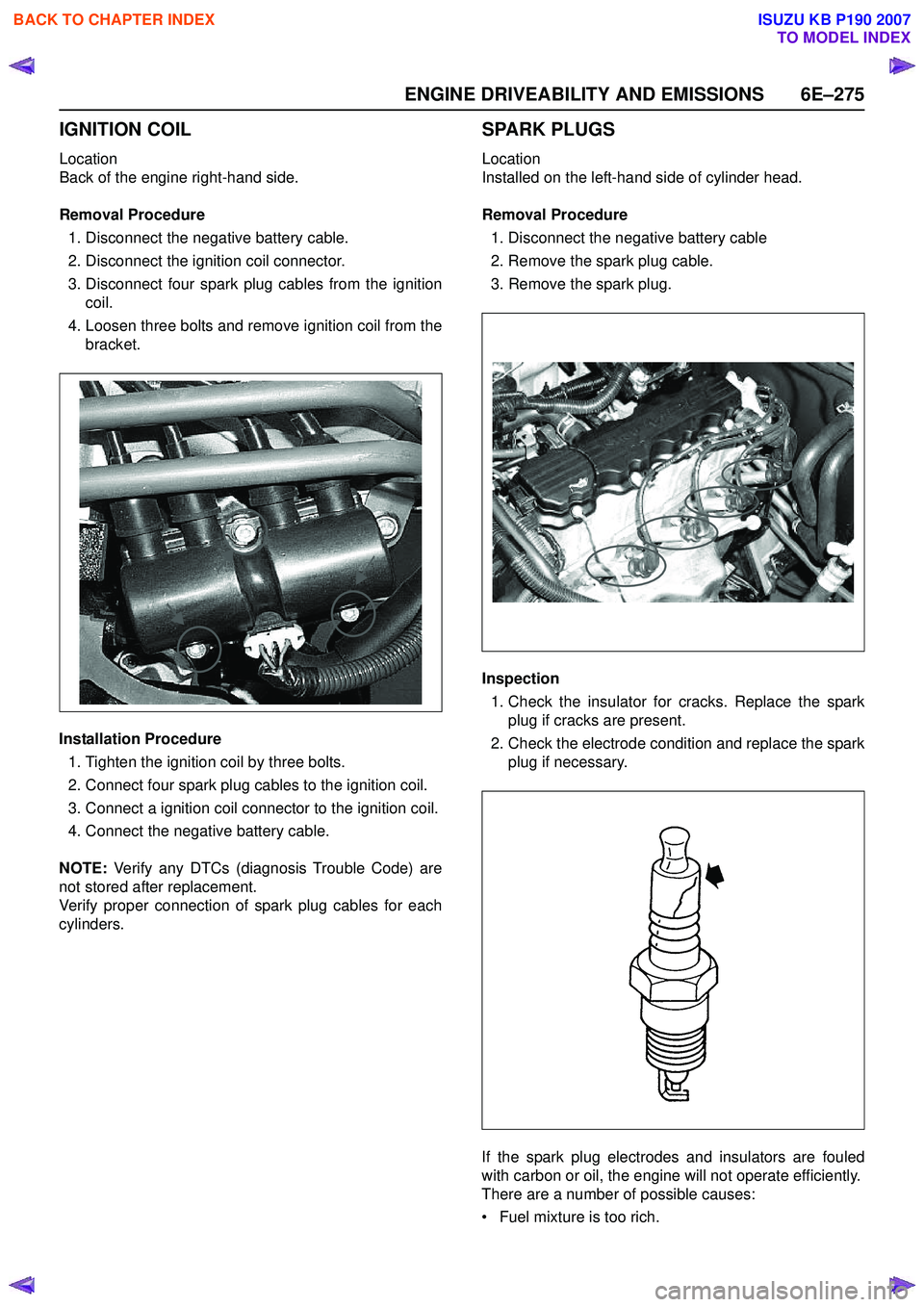
IGNITION COIL
Location
Back of the engine right-hand side.
Removal Procedure 1. Disconnect the negative battery cable.
2. Disconnect the ignition coil connector.
3. Disconnect four spark plug cables from the ignition coil.
4. Loosen three bolts and remove ignition coil from the bracket.
Installation Procedure 1. Tighten the ignition coil by three bolts.
2. Connect four spark plug cables to the ignition coil.
3. Connect a ignition coil connector to the ignition coil.
4. Connect the negative battery cable.
NOTE: Verify any DTCs (diagnosis Trouble Code) are
not stored after replacement.
Verify proper connection of spark plug cables for each
cylinders.
SPARK PLUGS
Location
Installed on the left-hand side of cylinder head.
Removal Procedure 1. Disconnect the negative battery cable
2. Remove the spark plug cable.
3. Remove the spark plug.
Inspection 1. Check the insulator for cracks. Replace the spark plug if cracks are present.
2. Check the electrode condition and replace the spark plug if necessary.
If the spark plug electrodes and insulators are fouled
with carbon or oil, the engine will not operate efficiently.
There are a number of possible causes:
• Fuel mixture is too rich.
BACK TO CHAPTER INDEX
TO MODEL INDEX
ISUZU KB P190 2007
Page 3182 of 6020
Engine Cooling – V6 Engine Page 6B1–47
Disconnection of the battery affects certain
vehicle electronic systems. Refer to 1.1
WARNING, CAUTION and NOTES, before
removing the ground lead.
2 Disconnect the battery ground lead. Refer to 8A – Electrical Body & Chassis.
Refer to ‘
‘‘
‘
Environmental Issues ’
’’
’
in 3.1
Service Notes, before draining the coolant.
3 Draining the coolant from the system. Refer to 3.3 Draining and Filling Cooling System in this Section.
4 Raise the front of the vehicle and support on safety stands. Refer to 0A General Information for the location of jacking and support points.
Always wear protective safety glasses when
working with spring type hose clamps.
Failure to do so could result in eye injury.
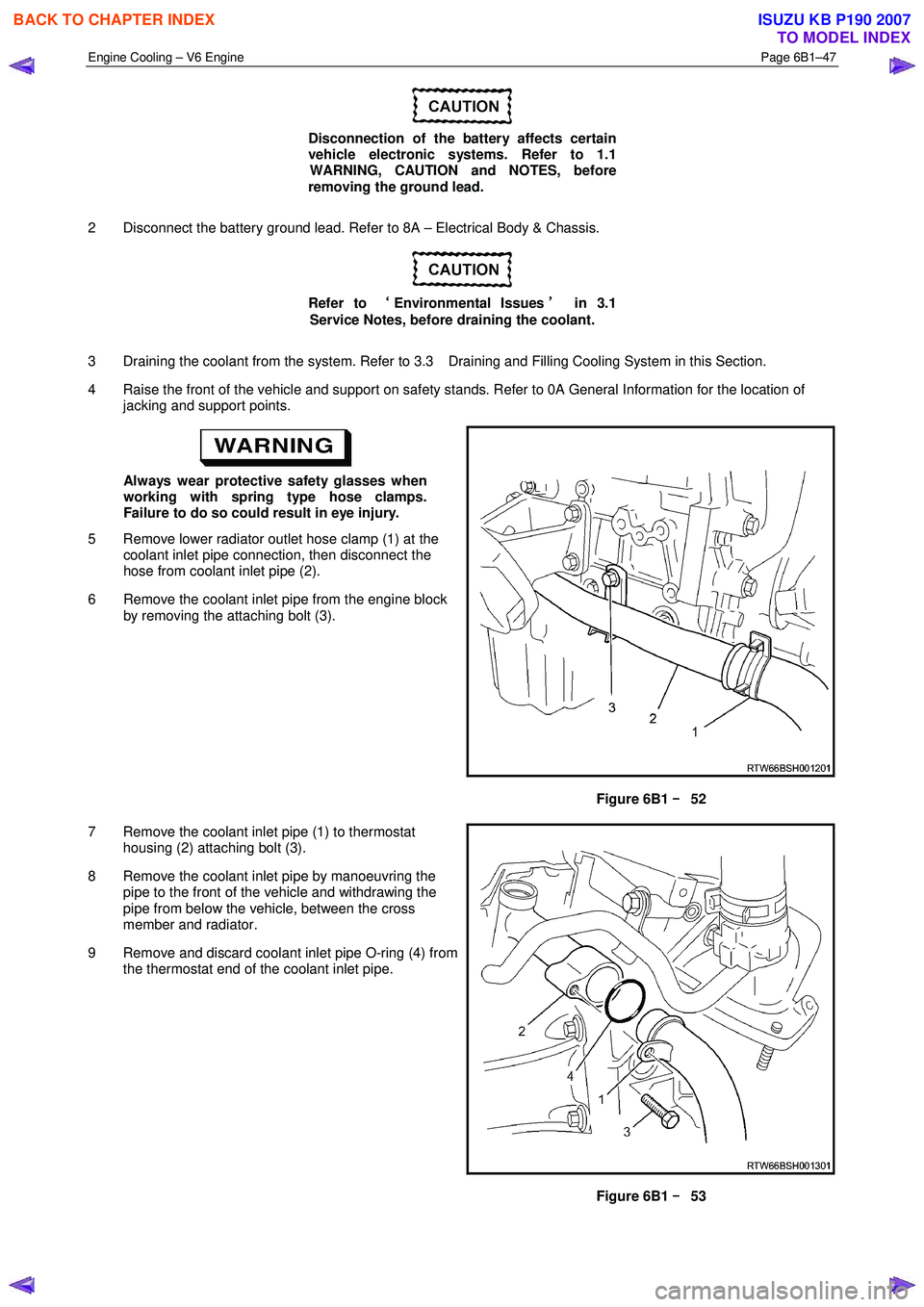
5 Remove lower radiator outlet hose clamp (1) at the coolant inlet pipe connection, then disconnect the
hose from coolant inlet pipe (2).
6 Remove the coolant inlet pipe from the engine block by removing the attaching bolt (3).
Figure 6B1 –
––
–
52
7 Remove the coolant inlet pipe (1) to thermostat housing (2) attaching bolt (3).
8 Remove the coolant inlet pipe by manoeuvring the pipe to the front of the vehicle and withdrawing the
pipe from below the vehicle, between the cross
member and radiator.
9 Remove and discard coolant inlet pipe O-ring (4) from the thermostat end of the coolant inlet pipe.
Figure 6B1 –
––
–
53
BACK TO CHAPTER INDEX
TO MODEL INDEX
ISUZU KB P190 2007
Page 3183 of 6020
Engine Cooling – V6 Engine Page 6B1–48
Install
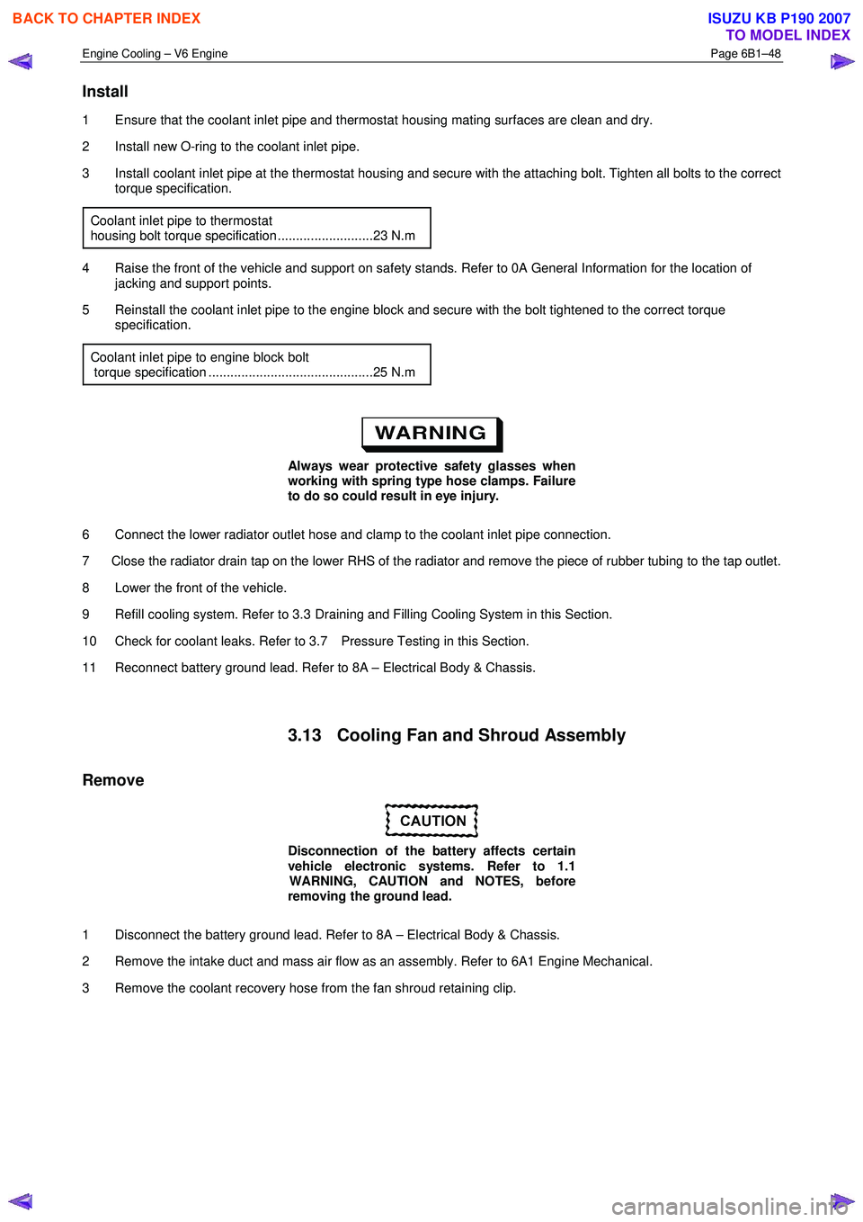
1 Ensure that the coolant inlet pipe and thermostat housing mating surfaces are clean and dry.
2 Install new O-ring to the coolant inlet pipe.
3 Install coolant inlet pipe at the thermostat housing and secure with the attaching bolt. Tighten all bolts to the correct torque specification.
Coolant inlet pipe to thermostat
housing bolt torque specification ..........................23 N.m
4 Raise the front of the vehicle and support on safety stands. Refer to 0A General Information for the location of jacking and support points.
5 Reinstall the coolant inlet pipe to the engine block and secure with the bolt tightened to the correct torque specification.
Coolant inlet pipe to engine block bolt
torque specification .............................................25 N.m
Always wear protective safety glasses when
working with spring type hose clamps. Failure
to do so could result in eye injury.
6 Connect the lower radiator outlet hose and clamp to the coolant inlet pipe connection.
7 Close the radiator drain tap on the lower RHS of the radiator and remove the piece of rubber tubing to the tap outlet.
8 Lower the front of the vehicle.
9 Refill cooling system. Refer to 3.3 Draining and Filling Cooling System in this Section.
10 Check for coolant leaks. Refer to 3.7 Pressure Testing in this Section.
11 Reconnect battery ground lead. Refer to 8A – Electrical Body & Chassis.
3.13 Cooling Fan and Shroud Assembly
Remove
Disconnection of the battery affects certain
vehicle electronic systems. Refer to 1.1
WARNING, CAUTION and NOTES, before
removing the ground lead.
1 Disconnect the battery ground lead. Refer to 8A – Electrical Body & Chassis.
2 Remove the intake duct and mass air flow as an assembly. Refer to 6A1 Engine Mechanical.
3 Remove the coolant recovery hose from the fan shroud retaining clip.
BACK TO CHAPTER INDEX
TO MODEL INDEX
ISUZU KB P190 2007
Page 3243 of 6020
Engine Management – V6 – General Information Page 6C1-1–1
6C1-1 Engine Management – V6
General Information
ATTENTION
Before performing any service operation or other procedure described in this Section, refer to 1.3 Warning
Caution and Notes for correct workshop practices with regard to safety and / or property damage.
1 General Information ............................................................................................................ ...................3
1.1 Introduction ............................................................................................................................................................ 3
1.2 Emission Control ................................................................................................................................................... 3
ADR 79/01 Emissions Standards .......................................................................................................................... 3
1.3 Warning Caution and Notes .................................................................................................................................. 4
Definition of WARNING, CAUTION and NOTE Statements ............................................................................. .... 4
WARNING defined ............................................................................................................................................. 4
CAUTION defined .............................................................................................................................................. 4
NOTE defined..................................................................................................................................................... 4
2 Component Locations ............................................................................................................ ...............5
2.1 Cylinder Numbering............................................................................................................................................... 5
2.2 Engine Compartment............................................................................................................................................. 5
2.3 Engine ..................................................................................................................................................................... 6
2.4 Interior..................................................................................................................................................................... 8
3 System Operation ...................................................................................................................................9
3.1 Fuel Delivery System ............................................................................................................................................. 9
Fuel System Pressure ........................................................................................................... ................................ 9
Fuel Injection System .......................................................................................................................................... 10
Short Term Fuel Trim ....................................................................................................................................... 10
Long Term Fuel Trim ........................................................................................................................................ 10
3.2 Air / Fuel Control System ...................................................................................................... .............................. 11
Starting Mode ....................................................................................................................................................... 11
Run Mode.............................................................................................................................................................. 11
Open Loop Mode................................................................................................................. ............................. 11
Closed Loop Mode ............................................................................................................... ............................ 11
Acceleration Mode .............................................................................................................. ................................. 11
Deceleration Mode ............................................................................................................................................... 11
Fuel Shut-off Mode .............................................................................................................................................. 11
Battery Voltage Correction Mode ................................................................................................ ....................... 12
Limp Mode ............................................................................................................................................................ 12
Engine Protection Mode ......................................................................................................... ............................. 12
Clear Flood Mode ................................................................................................................................................. 12
3.3 Ignition Control System........................................................................................................ ............................... 12
3.4 Starter Motor Operation....................................................................................................................................... 12
3.5 Throttle Actuator Control System ............................................................................................... ....................... 12
Description ........................................................................................................................................................... 12
Throttle Body Relearn Procedure ....................................................................................................................... 14
TAC System Default Actions / Reduce Power Modes................................................................................ ....... 14
Forced Engine Shutdown .................................................................................................................................... 14
3.6 Cruise Control System ........................................................................................................................................ 14
3.7 Brake Torque Management ........................................................................................................ ......................... 15
3.8 Emission Control Systems.................................................................................................................................. 15
Evaporative Emission Control System ............................................................................................ .................. 15
Engine Ventilation System .................................................................................................................................. 16
BACK TO CHAPTER INDEX
TO MODEL INDEX
ISUZU KB P190 2007