2007 ISUZU KB P190 battery location
[x] Cancel search: battery locationPage 5685 of 6020
RESTRAINT CONTROL SYSTEM 9A1-3
Diagnostic Information
CAUTION: When fasteners are removed, always
reinstall them at the same location from which they
were removed. If a fastener needs to be replaced,
use the correct part number fastener for that
application. If the correct part number fastener is
not available, a fastener of equal size and strength
(or stronger) may be used. Fasteners that are not
reused, and those requiring thread locking
compound, will be called out. The correct torque
value must be used when installing fasteners that
require it. If the above conditions are not followed,
parts or system damage could result.
Diagnostic Procedures
WARNING: TO AVOID DEPLOYMENT WHEN
TROUBLESHOOTING THE SRS, DO NOT USE
ELECTRICAL TEST EQUIPMENT SUCH AS
A
BATTERY-POWERED OR AC-POWERED
VOLTMETER, OHMMETER, ETC., OR ANY TYPE OF
ELECTRICAL EQUIPMENT OTHER THAN THAT
SPECIFIED IN THIS MANUAL. DO NOT USE A NON-
POWERED, PROBE-TYPE TESTER.
INSTRUCTIONS IN THIS MANUAL MUST BE
FOLLOWED CAREFULLY, OTHERWISE PERSONAL
INJURY MAY RESULT.
The diagnostic procedures used in this section are
designed to aid in finding and repairing SRS problems.
Outlined below are the steps to find and repair SRS
problems quickly and effectively. Failure to carefull
y
follow these procedures may result in extended
diagnostic time, incorrect diagnosis and incorrect parts
replacement.
1. Perform The “SRS Diagnostic System Check”.
The “SRS Diagnostic System Check” should always be the starting point of any SRS diagnostics. The
“SRS Diagnostic System Check” checks for prope
r
“SRS” warning lamp operation and checks for SRS
trouble codes using both “Flash Code” and “Scan
Tool” Methods.
2. Refer To The Proper Diagnostic Chart As Directed By The “SRS Diagnostic System
Check”.
The “SRS Diagnostic System Check” will lead you to the correct chart to diagnose any SRS problems.
Bypassing these procedures may result in extended
diagnostic time, incorrect diagnosis and incorrect
parts replacement.
3. Repeat The “SRS Diagnostic System Check”
After Any Repair Or Diagnostic Procedures Has
Been Performed.
Performing the “SRS Diagnostic System Check” after all repairs or diagnostic procedures, will assure
that the repair has been made correctly and that no
other conditions exist.
Diagnostic Codes
The SRS control unit maintains a history record of all
diagnostic codes that have been detected since the
SRS codes were last cleared during service.
1. Active Codes - Faults that are presently detected in this ignition cycle. Active codes are stored in RAM
(Random Access Memory).
2. History Codes - All faults detected since the last time the history fault memory was cleared. History codes
are stored in the EEPROM. (Electronically Erasable
Programmable Read only Memory)
How To Read Trouble Codes
All codes (Active and history) can be read (or cleared)
by using a scan tool or equivalent.
If a PDT is not available, have the vehicle serviced by a
HOLDEN dealer.
How To Clear Trouble Codes
Trouble codes can only be cleared by using a Scan
Tool. If a “scan tool” is not available then inform the
owner of the stored codes and suggest that the codes
are cleared upon the next visit to a ISUZU/GM
dealership.
Scan Tool Diagnostics
A scan tool can be used to read current and history
codes and to clear all history codes after a repair is
complete. The scan tool must be updated to
communicate with the SRS through a replaceable
cartridge or a manufacturer's update before it can be
used for SRS diagnostics. To use the scan tool,
connect it to the DLC and turn the ignition switch “ON”.
Then follow the manufacturer's directions fo
r
communication with the SRS. The scan tool reads
serial data from the SRS control unit’s “Serial Data”
output (terminal 21) to the DLC (terminal 2).
BACK TO CHAPTER INDEX TO MODEL INDEX
ISUZU KB P190 2007
Page 5859 of 6020
11A-8 IMMOBILIZER CONTROL SYSTEM (4JK1/4JJ1/HFV6)
Diagnostic Information and Procedures
Diagnostic Starting Point - Immobilizer
Controls
Begin the system diagnosis with Diagnostic System
Check - Immobilizer Controls. The Diagnostic System
Check - Immobilizer Controls will provide the following
information:
• The identification of the control modules which command the system.
• The ability of the control modules to communicate through the serial data circuit.
• The identification of any stored diagnostic trouble codes (DTCs) and the their statuses.
The use of the Diagnostic System Check - Immobilizer
Controls will identify the correct procedure for
diagnosing the system and where the procedure is
located.
Diagnostic System Check - Immobilizer
Controls
Description
The Diagnostic System Check - Immobilizer Controls is
an organized approach to identifying a condition that is
created by a malfunction in the electronic immobilizer
control system. The Diagnostic System Check must be
the starting point for any immobilizer system concern.
The Diagnostic System Check directs the service
technician to the next logical step in order to diagnose
the concern. Understanding and correctly using the
diagnostic table reduces diagnostic time, and prevents
the replacement of good parts. Test Description
The numbers below refer to the step numbers on the
diagnostic table.
2. Lack of communication may be because of a partial
or a total malfunction of the serial data circuit.
6. The presence of DTCs which begin with U, indicate
that some other module is not communicating.
9. If there are other modules with DTCs set, refer to the
DTC list. The DTC list directs you to the appropriate
diagnostic procedure.
Important: • DO NOT perform this diagnostic if there is not an immobilizer system concern, unless another
procedure directs you to this diagnostic.
• Before you proceed with diagnosis, search for applicable service bulletins.
• Unless a diagnostic procedure instructs you, DO NOT clear the DTCs.
• Ensure the battery has a full charge.
• Ensure the battery cables (+) (-) are clean and tight.
• Ensure the ICU ground is clean, tight, and in the correct location.
• Ensure the ICU harness connector is clean and correctly connected.
• Ensure the ICU terminals are clean and correctly mating.
• Ensure the immobilizer security information is correctly programmed into the ICU, ECM and PIM.
• Ensure the ICU is correctly installed to the steering lock.
• Ensure objects does not block transponder key in the steering lock.
• Ensure another transponder key is not attached to the key ring.
Diagnostic System Check - Immobilizer Controls
Step Action Value(s)Yes No
1 Install a scan tool.
Does the scan tool turn ON? —
Go to Step 2 Go to Scan Tool
Does Not Power Up
2 1. Turn ON the ignition, with the engine OFF.
2. Attempt to establish communication with the listed control modules.
•ICU
• Engine control module (ECM)
• Powertrain interface module (PIM)
• Transmission control module (TCM) (AISIN A/T or 4L-60E)
Does the scan tool communicate with all the listed
control modules? —
Go to Step 3 Go to Scan Tool
Does Not
Communicate with CAN Device
BACK TO CHAPTER INDEX TO MODEL INDEX
ISUZU KB P190 2007
Page 5863 of 6020
11A-12 IMMOBILIZER CONTROL SYSTEM (4JK1/4JJ1/HFV6)
Scan Tool Does Not Power Up
Circuit Description
The data link connector (DLC) is a standardized 16-
cavity connector. Connector design and location is
dictated by an industry wide standard, and is required
to provide the following:
• Scan tool power battery positive voltage at terminal 16.
• Scan tool power ground at terminal 4. • Common signal ground at terminal 5.
The scan tool will power up with the ignition OFF. Some
modules however, will not communicate unless the
ignition is ON.
Schematic Reference: Immobilizer Controls
Schematics
Connector End View Reference: ICU Connector End
View
Circuit/ System Testing Scan Tool Does Not Power Up
Step Action Value(s)Yes No
1 Important
: Make sure the scan tool works properly
on another vehicle before using this chart.
1. Turn OFF the ignition.
2. Inspect the Meter (+B) (10A) fuse in the cabin fuse block.
Is the Meter (+B) (10A) fuse open? —
Go to Step 2 Go to Step 3
2 Replace the Meter (+B) (10A) fuse. If the fuse
continues to open, repair the short to ground on
one of the circuits that is fed by the Meter (+B)
(10A) fuse or replace the shorted attached
component.
Did you complete the repair? —
Go to Step 7
—
31. Check each circuit at the data link connector
(DLC) (B-58) for a backed out, spread or
missing terminal.
2. Repair the terminal as necessary.
Did you find and complete the repair? —
Go to Step 7 Go to Step 4
4 Connect a test lamp between the +B circuit (pin 16
of B-58) at the DLC and a known good ground.
Does the test lamp illuminate? —
Go to Step 6 Go to Step 5
5 Repair the open in the battery voltage circuit to the
DLC.
Did you complete the repair? —
Go to Step 7
—
61. Test each ground circuit at the DLC (pins 4
and 5 of B-58) for an open circuit or high
resistance.
2. Repair the circuit(s), clean or tighten ground as necessary.
Did you find and correct the condition? —
Go to Step 7 Go to Intermittent
Conditions
7 1. Connect the scan tool to the DLC.
2. Attempt to turn ON the scan tool.
Does the scan tool ON? —
System OK Go to Step 1
BACK TO CHAPTER INDEX
TO MODEL INDEX
ISUZU KB P190 2007
Page 5925 of 6020
IMMOBILIZER SYSTEM (C24SE, 4JA1-T) 11A-27
Diagnostic procedure
• Once the cause of DTC is repaired or gone,
engine can be operated normally, and present
DTC becomes history code.
• History code is canceled by no repeat failure on 25
consequence ignition key on afterward.
• History code cannot be canceled by batter
y
connector disconnected.
Clearing Diagnostic Trouble Codes
IMPORTANT: Do not clear DTCs unless directed to do
so by the service information provided for each
diagnostic procedure. W hen DTCs are cleared, the
Failure Record data which may help diagnose an
intermittent fault will also be erased from memory.
Verifying Vehicle Repair
Verification of vehicle repair will be more
comprehensive for vehicles with immobilizer system
diagnostic. Following a repair, the technician should
perform the following steps:
1. Review and record the Fail Records for the DTC
which has been diagnosed.
2. Clear DTC(s).
3. Operate the vehicle within conditions noted in the
Fail Records.
4. Monitor the DTC status information for the DTC
which has been diagnosed until the diagnostic test
associated with that DTC runs.
Following these steps are very important in verifying
repairs on immobilizer systems. Failure to follow these
steps could result in unnecessary repairs.
Diagnostic Aids
Check the condition for system parts.
• Installation condition, poor connection, damage,
system parts malfunction. Harness, Fuse, Relay,
Immobilizer coil (antenna), Key, Meter, Immobilize
r
control unit (ICU), Engine control module (ECM).
NOTE: Breakage of immobilizer fuse does not operate
immobilizer system. Check engine lamp flashes at this
time.
Check the Electro-Magnetic Interference (EMI)
• Location of vehicle check
Move the vehicle to a new location and perform
the check again.
• Non-OEM Parts.
Switch is "OFF" or remove the Non-OEM parts and
perform the check again.
• Other
Remove the accessory and another key from key.
Check the other items.
• Battery voltage is low.
• Immobilizer programming functions.
Must be programmed immobilizer system.
• Registration for security code, immobilizer control
unit parts number.
• Key switch operation.
Immobilizer system may detect a history DTC b
y
the timing of ON-OFF of a key switch.
• Active the immobilizer system.
• Keyless entry system is malfunction.
• Anti theft system is malfunction.
Check the operation
Check the operation "Lock / unlock" by using transmitte
r
(key) on the vehicle.
BACK TO CHAPTER INDEX TO MODEL INDEX
ISUZU KB P190 2007
Page 5955 of 6020
ANTITHEFT SYSTEM 11B-1
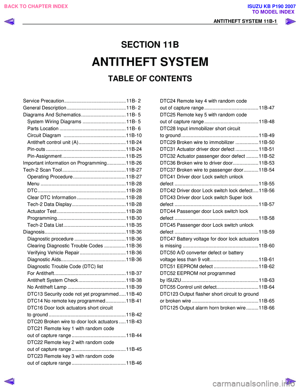
SECTION 11B
ANTITHEFT SYSTEM
TABLE OF CONTENTS
Service Precaution .................................................. 11B- 2
General Description ................................................ 11B- 2
Diagrams And Schematics ................................. 11B- 5 System W iring Diagrams ................................ 11B- 5
Parts Location ................................................. 11B- 6
Circuit Diagram ..............................................11B-10
Antitheft control unit (A) ...................................11B-24
Pin-outs ...........................................................11B-24
Pin-Assignment ...............................................11B-25
lmportant information on Programming..............11B-26
Tech-2 Scan Tool ...............................................11B-27 Operating Procedure .......................................11B-27
Menu ...............................................................11B-28
DTC .................................................................11B-28
Clear DTC Information ....................................11B-28
Tech-2 Data Display........................................11B-28
Actuator Test ...................................................11B-28
Programming...................................................11B-30
Tech-2 Data List ..............................................11B-35
Diagnosis............................................................11B-36 Diagnostic procedure ......................................11B-36
Clearing Diagnostic Trouble Codes ................11B-36
Verifying Vehicle Repair ..................................11B-36
Diagnostic Aids................................................11B-36
Diagnostic Trouble Code (DTC) list
For Antitheft.....................................................11B-37
Antitheft System Check ...................................11B-38
No Antitheft Lamp ...........................................11B-39
DTC13 Security code not yet programmed .....11B-40
DTC14 No remote key programmed ...............11B-41
DTC16 Door lock actuators short circuit
to ground .........................................................11B-42
DTC20 Broken wire to door lock actuators .....11B-43
DTC21 Remote key 1 with random code
out of capture range ........................................11B-44
DTC22 Remote key 2 with random code
out of capture range ........................................11B-45
DTC23 Remote key 3 with random code
out of capture range ........................................11B-46
DTC24 Remote key 4 with random code
out of capture range ........................................ 11B-47
DTC25 Remote key 5 with random code
out of capture range ........................................ 11B-48
DTC28 Input immobilizer short circuit
to ground ......................................................... 11B-49
DTC29 Broken wire to immobilizer ................. 11B-50
DTC31 Actuator driver door defect ................. 11B-51
DTC32 Actuator passenger door defect ......... 11B-52
DTC36 Broken wire to driver door................... 11B-53
DTC37 Broken wire to passenger door........... 11B-54
DTC41 Driver door Lock switch unlock
defect .............................................................. 11B-55
DTC42 Driver door Lock switch lock defect .... 11B-56
DTC43 Driver door Lock switch Super lock
defect .............................................................. 11B-57
DTC44 Passenger door Lock switch lock
defect .............................................................. 11B-58
DTC45 Passenger door Lock switch unlock
defect .............................................................. 11B-59
DTC47 Battery voltage for door lock actuators
is missing ........................................................ 11B-60
DTC50 A/D converter defect or battery
voltage less than 9 volt.................................... 11B-61
DTC51 EEPROM defect ................................. 11B-62
DTC52 EEPROM not programmed
by ISUZU ......................................................... 11B-63
DTC55 Control unit defect............................... 11B-64
DTC123 Output flasher short circuit to ground
or broken wire ................................................. 11B-65
DTC125 Output alarm horn broken wire ......... 11B-66
BACK TO CHAPTER INDEX TO MODEL INDEX
ISUZU KB P190 2007
Page 5990 of 6020
11B-36 ANTITHEFT SYSTEM
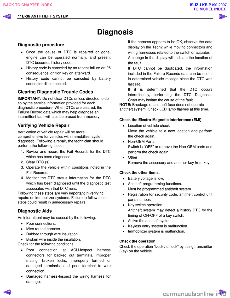
Diagnosis
Diagnostic procedure
• Once the cause of DTC is repaired or gone,
engine can be operated normally, and present
DTC becomes history code.
• History code is canceled by no repeat failure on 25
consequence ignition key on afterward.
• History code cannot be canceled by batter
y
connector disconnected.
Clearing Diagnostic Trouble Codes
IMPORTANT: Do not clear DTCs unless directed to do
so by the service information provided for each
diagnostic procedure. W hen DTCs are cleared, the
Failure Record data which may help diagnose an
intermittent fault will also be erased from memory.
Verifying Vehicle Repair
Verification of vehicle repair will be more
comprehensive for vehicles with immobilizer system
diagnostic. Following a repair, the technician should
perform the following steps:
1. Review and record the Fail Records for the DTC which has been diagnosed.
2. Clear DTC (s).
3. Operate the vehicle within conditions noted in the Fail Records.
4. Monitor the DTC status information for the DTC which has been diagnosed until the diagnostic test
associated with that DTC runs.
Following these steps are very important in verifying
repairs on immobilizer systems. Failure to follow these
steps could result in unnecessary repairs.
Diagnostic Aids
An intermittent may be caused by the following:
• Poor connections.
• Miss routed harness.
• Rubbed through wire insulation.
• Broken wire inside the insulation.
Check for the following conditions:
• Poor connection at ACU-Inspect harness
connectors for backed out terminals, imprope
r
mating, broken locks, improperly formed or
damaged terminals, and poor terminal to wire
connection.
• Damaged harness-Inspect the wiring harness fo
r
damage.
If the harness appears to be OK, observe the data
display on the Tech2 while moving connectors and
wiring harnesses related to the switch or actuator.
A change in the display will indicate the location of
the fault.
If DTC cannot be duplicated, the information included in the Failure Records data can be useful
in determined vehicle mileage since the DTC was
last set.
If it is determined that the DTC occurs intermittently, performing the DTC Diagnostic
Chart may isolate the cause of the fault.
NOTE: Breakage of antitheft fuse does not operate
antitheft system. Check LED lamp flashes at this time.
Check the Electro-Magnetic Interference (EMI)
• Location of vehicle check
Move the vehicle to a new location and perform
the check again.
• Non-OEM Parts.
Switch is “OFF” or remove the Non-OEM parts and
perform the check again.
• Other
Remove the accessory and another key from key.
Check the other items.
• Battery voltage is low.
• Antitheft programming functions.
Must be programmed antitheft system.
• Registration for security code, antitheft control unit
parts number.
• Key switch operation.
Antitheft system may detect a history DTC by the
timing of ON-OFF of a key switch.
• Active the antitheft system.
• Keyless entry system is malfunction.
• Immobilizer system is malfunction.
Check the operation
Check the operation "Lock / unlock" by using transmitter
(key) on the vehicle.
BACK TO CHAPTER INDEX TO MODEL INDEX
ISUZU KB P190 2007