2007 ISUZU KB P190 turn signal
[x] Cancel search: turn signalPage 3366 of 6020
Engine Management – V6 – Diagnostics Page 6C1-2–88
• DTC P0153 – HO2S Circuit Slow Response – Bank 2 Sensor 1
Circuit Description
The wide band heated oxygen sensor (HO2S) measures the amount of oxygen in the exhaust system and provides
more information than the switching style HO2S. The wide band sensor consists of an oxygen sensing cell, an oxygen
pumping cell, and a heater.
The exhaust gas sample passes through a diffusion gap between the sensing cell and the pumping cell. The engine
control module (ECM) supplies a voltage to the HO2S and uses this voltage as a reference to the amount of oxygen in
the exhaust system. An electronic circuit within the ECM controls the pump current through the oxygen pumping cell to
maintain a constant voltage in the oxygen sensing cell. The ECM monitors the voltage variation in the sensing cell and
attempts to keep the voltage constant by increasing or decreasing the amount of current flow, or oxygen ion flow, to the
pumping cell.
By measuring the amount of current required to maintain the voltage in the sensing cell, the ECM can determine the
concentration of oxygen in the exhaust. The HO2S voltage is displayed as a lambda value. A lambda value of 1 is equal
to a stoichiometric air fuel ratio of 14.7:1. Under normal operating conditions, the lambda value will remain around 1.
W hen the fuel system is lean, the oxygen level will be high and the lambda signal will be high or more than 1. W hen the
fuel system is rich, the oxygen level will be low, and the lambda signal will be low or less than 1. The ECM uses this
information to maintain the correct air / fuel ratio.
Conditions for Running the DTC
• Before the ECM can report DTC P0133 or P0153 failed, DTCs P0121, P0122, P0123, P0221, P0222, P0223,
P0336, P0338, P2237, and P2240 must run and pass.
• DTCs P0030, P0031, P0032, P0050, P0051, P0052, P0053, P0059, P0130, P0131, P0132, P0135, P0150, P0151,
P0151, P0152, P0155, P0442, P0443, P0446, P0455, P0458, P0459, P0496, P167A, P167B, P2096, P2097,
P2098, P2099, P2231, P2234, P2243, P2247, P2251, P2254, P2297, P2298, P2626, and P2629 are not set.
• The HO2S is at operating temperature.
• The HO2S is between 0.94 – 1.06 lambda.
• The engine speed is between 1,480 – 2,040 rpm.
• The volumetric efficiency is between 16.5 – 38.3 percent.
• The change in volumetric efficiency is less than 3 percent.
• The evaporative emission (EVAP) purge is not active, or the ECM determines the EVAP hydrocarbon (HC)
concentration is less than a predetermined amount when EVAP purge is active.
• The long term fuel trim correction is active.
• DTCs P0133 and P0153 run continuously once the above conditions are met for 10 minutes.
Conditions for Setting the DTC
• The ECM has determined that the dynamic value of the affected HO2S is less than a predetermined threshold.
• The above condition is met for more than 4 seconds.
Action Taken When the DTC Sets
• The ECM illuminates the malfunction indicator lamp (MIL) on the second consecutive ignition cycle that the
diagnostic runs and fails.
• The control module records the operating conditions at the time the diagnostic fails. The first time the diagnostic
fails, the control module stores this information in the Failure Records. If the diagnostic reports a failure on the
second consecutive ignition cycle, the control module records the operating conditions at the time of the failure.
The control module writes the operating conditions to the Freeze Frame and updates the Failure Records.
Conditions for Clearing the MIL/DTC
• The ECM turns OFF the malfunction indicator lamp (MIL) after four consecutive ignition cycles that the diagnostic
runs and does not fail.
• A current DTC, Last Test Failed, clears when the diagnostic runs and passes.
BACK TO CHAPTER INDEX
TO MODEL INDEX
ISUZU KB P190 2007
Page 3369 of 6020
Engine Management – V6 – Diagnostics Page 6C1-2–91
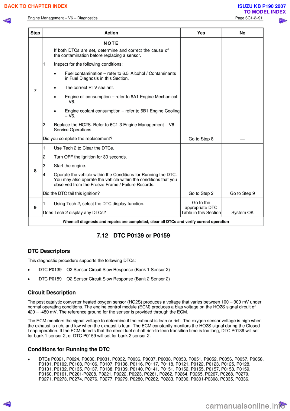
Step Action Yes No
7 NOTE
If both DTCs are set, determine and correct the cause of
the contamination before replacing a sensor.
1 Inspect for the following conditions:
• Fuel contamination – refer to 6.5 Alcohol / Contaminants
in Fuel Diagnosis in this Section.
• The correct RTV sealant.
• Engine oil consumption – refer to 6A1 Engine Mechanical
– V6.
• Engine coolant consumption – refer to 6B1 Engine Cooling
– V6.
2 Replace the HO2S. Refer to 6C1-3 Engine Management – V6 – Service Operations.
Did you complete the replacement? Go to Step 8 —
8 1 Use Tech 2 to Clear the DTCs.
2 Turn OFF the ignition for 30 seconds.
3 Start the engine.
4 Operate the vehicle within the Conditions for Running the DTC. You may also operate the vehicle within the conditions that you
observed from the Freeze Frame / Failure Records.
Did the DTC fail this ignition? Go to Step 2 Go to Step 9
9 1 Using Tech 2, select the DTC display function.
Does Tech 2 display any DTCs? Go to the
appropriate DTC
Table in this Section System OK
When all diagnosis and repairs are completed, clear all DTCs and verify correct operation
7.12 DTC P0139 or P0159
DTC Descriptors
This diagnostic procedure supports the following DTCs:
• DTC P0139 – O2 Sensor Circuit Slow Response (Bank 1 Sensor 2)
• DTC P0159 – O2 Sensor Circuit Slow Response (Bank 2 Sensor 2)
Circuit Description
The post catalytic converter heated oxygen sensor (HO2S) produces a voltage that varies between 100 – 900 mV under
normal operating conditions. The engine control module (ECM) produces a bias voltage on the HO2S signal circuit of
420 – -480 mV. The reference ground for the sensor is provided through the ECM.
The ECM monitors the signal voltage to determine if the exhaust is lean or rich. The oxygen sensor voltage is high when
the exhaust is rich, and low when the exhaust is lean. The ECM constantly monitors the HO2S signal during the Closed
Loop operation. If the ECM detects that the decel fuel cut-off rich-to-lean transition time is too long, DTC P0139 will set
for bank 1 sensor 2, or DTC P0159 will set for bank 2 sensor 2.
Conditions for Running the DTC
• DTCs P0021, P0024, P0030, P0031, P0032, P0036, P0037, P0038, P0050, P0051, P0052, P0056, P0057, P0058,
P0101, P0102, P0103, P0106, P0107, P0108, P0116, P0117, P0118, P0121, P0122, P0123, P0125, P0128,
P0131, P0132, P0135, P0137, P0138, P0139, P0140, P0141, P0151, P0152, P0155, P0157, P0158, P0159,
P0160, P0161, P0201-P0208, P0221, P0222, P0223, P0261, P0262, P0264, P0265, P0267, P0268, P0270,
P0271, P0273, P0274, P0276, P0277, P0279, P0280, P0282, P0283, P0300, P0301-P0308, P0335, P0336,
BACK TO CHAPTER INDEX
TO MODEL INDEX
ISUZU KB P190 2007
Page 3380 of 6020
Engine Management – V6 – Diagnostics Page 6C1-2–102
3-way catalytic converter damage. The malfunction indicator lamp (MIL) will flash ON and OFF when the conditions for
catalytic converter damage are present. DTCs P0301 through P0306 correspond to cylinders 1 through 6. If the ECM is
able to determine that a specific cylinder is misfiring, the DTC for that cylinder will set. If the misfire rate is sufficient to
cause emission levels to exceed a predetermined value, this DTC sets.
Conditions for Running the DTC
• DTCs P0121, P0122, P0123, P0221, P0222, P0223, P0335, P0336, or P0338 are not set.
• The engine speed is between 400 – 7,000 rpm and steady.
• The delivered torque signal is more than 10 percent at idle.
• The delivered torque signal is between 9 – 30 percent with the transmission in drive.
• The intake air temperature (IAT) is more than –30° C.
• The fuel level is more than 12 percent.
• The torque management is not active.
• DTC P0300 runs continuously when the above conditions exist for at least 1,000 engine revolutions.
Conditions for Setting the DTC
• The ECM detects a crankshaft rotation speed variation indicating a misfire rate sufficient to cause emissions levels
to exceed mandated standards.
• The condition above exists for more than 4 seconds.
Action Taken When the DTC Sets
• The control module activates the MIL on the second ignition cycle that the diagnostic runs and fails.
• The control module records the operating conditions at the time the diagnostic fails. The first time the diagnostic
fails, the control module stores this information in the Failure Records. If the diagnostic reports a failure on the
second consecutive ignition cycle, the control module records the operating conditions at the time of the failure.
The control module writes the operating conditions to the Freeze Frame and updates the Failure Records.
Conditions for Clearing the MIL/DTC
• The ECM turns OFF the malfunction indicator lamp (MIL) after four consecutive ignition cycles that the diagnostic
runs and does not fail.
• A current DTC, Last Test Failed, clears when the diagnostic runs and passes.
• A history DTC clears after 40 consecutive warm-up cycles, if no failures are reported by this or any other emission
related diagnostic.
• Use Tech 2 to clear the MIL and the DTC.
Additional Information
• A misfire DTC could be caused by an excessive vibration from sources other than the engine. Inspect for the
following possible sources:
− A tyre or wheel that is out of round or out of balance
− Variable thickness brake rotors
− An unbalanced drive shaft
− Certain rough road conditions
− A damaged accessory drive component or belt
• A misfire DTC could be caused by a camshaft actuator stuck in the full advance or retard position.
• For an intermittent condition, refer to 5.2 Intermittent Fault Conditions in this Section.
BACK TO CHAPTER INDEX
TO MODEL INDEX
ISUZU KB P190 2007
Page 3383 of 6020
Engine Management – V6 – Diagnostics Page 6C1-2–105
Circuit Description
The engine control module (ECM) uses information from the crankshaft position (CKP) sensor and the camshaft position
(CMP) sensor to determine when an engine misfire is occurring. By monitoring variations in the crankshaft rotation
speed for each cylinder, the ECM is able to detect individual misfire events. A misfire rate that is high enough can cause
3-way catalytic converter damage. The malfunction indicator lamp (MIL) will flash ON and OFF when the conditions for
catalytic converter damage are preset. DTCs P0301 – P0306 correspond to cylinders 1 to 6. If the ECM is able to
determine that a specific cylinder is misfiring, the DTC for that cylinder sets.
Conditions for Running the DTC
• DTCs P0121, P0122, P0123, P0221, P0222, P0223, P0335, P0336, or P0338 are not set.
• The engine speed is between 400 – 7,000 rpm and steady.
• The delivered torque signal is more than 10 percent at idle with the transmission in neutral.
• The delivered torque signal is between 10 – 30 percent with the transmission in drive.
• The intake air temperature (IAT) is more than –30° C.
• The engine run time is more than 45 seconds.
• The fuel level is more than 12 percent.
• The torque management is not active.
• DTCs P0301, P0302, P0303, P0304, P0305, and P0306 run continuously when the above conditions exist for at
least 1,000 engine revolutions.
Conditions for Setting the DTC
• The ECM detects a crankshaft rotation speed variation indicating a single cylinder misfire rate sufficient to cause
emissions levels to exceed mandated standards.
• The condition exists for more than 4 seconds.
Action Taken When the DTC Sets
• The control module activates the MIL on the second ignition cycle that the diagnostic runs and fails.
• The control module records the operating conditions at the time the diagnostic fails. The first time the diagnostic
fails, the control module stores this information in the Failure Records. If the diagnostic reports a failure on the
second consecutive ignition cycle, the control module records the operating conditions at the time of the failure.
The control module writes the operating conditions to the Freeze Frame and updates the Failure Records.
Conditions for Clearing the MIL/DTC
• The ECM turns OFF the malfunction indicator lamp (MIL) after four consecutive ignition cycles that the diagnostic
runs and does not fail.
• A current DTC, Last Test Failed, clears when the diagnostic runs and passes.
• A history DTC clears after 40 consecutive warm-up cycles, if no failures are reported by this or any other emission
related diagnostic.
• Use Tech 2 to clear the MIL and the DTC.
Additional Information
• A misfire DTC could be caused by an excessive vibration from sources other than the engine. Check for the
following possible sources:
− Tyre or wheel out of round or balance
− Variable thickness brake rotor or drum
− Drive shaft not balanced
− Certain rough road conditions
BACK TO CHAPTER INDEX
TO MODEL INDEX
ISUZU KB P190 2007
Page 3385 of 6020
Engine Management – V6 – Diagnostics Page 6C1-2–107
Step Action Yes No
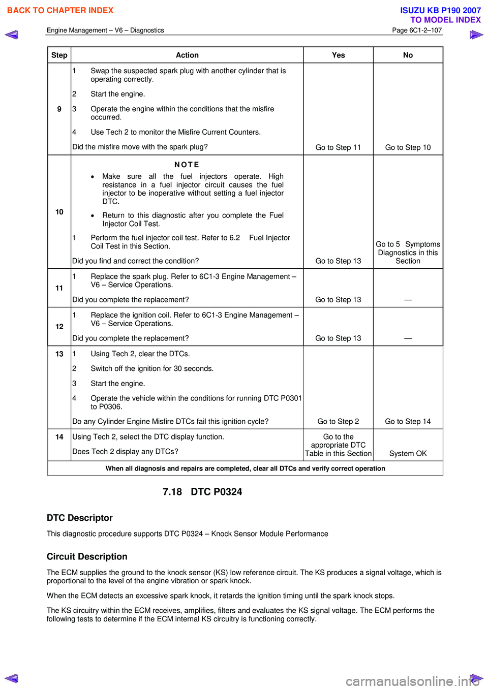
9 1 Swap the suspected spark plug with another cylinder that is
operating correctly.
2 Start the engine.
3 Operate the engine within the conditions that the misfire occurred.
4 Use Tech 2 to monitor the Misfire Current Counters.
Did the misfire move with the spark plug? Go to Step 11 Go to Step 10
10 NOTE
• Make sure all the fuel injectors operate. High
resistance in a fuel injector circuit causes the fuel
injector to be inoperative without setting a fuel injector
DTC.
• Return to this diagnostic after you complete the Fuel
Injector Coil Test.
1 Perform the fuel injector coil test. Refer to 6.2 Fuel Injector Coil Test in this Section.
Did you find and correct the condition? Go to Step 13 Go to 5 Symptoms
Diagnostics in this Section
11 1 Replace the spark plug. Refer to 6C1-3 Engine Management –
V6 – Service Operations.
Did you complete the replacement? Go to Step 13 —
12 1 Replace the ignition coil. Refer to 6C1-3 Engine Management –
V6 – Service Operations.
Did you complete the replacement? Go to Step 13 —
13 1 Using Tech 2, clear the DTCs.
2 Switch off the ignition for 30 seconds.
3 Start the engine.
4 Operate the vehicle within the conditions for running DTC P0301 to P0306.
Do any Cylinder Engine Misfire DTCs fail this ignition cycle? Go to Step 2 Go to Step 14
14 Using Tech 2, select the DTC display function.
Does Tech 2 display any DTCs? Go to the
appropriate DTC
Table in this Section System OK
When all diagnosis and repairs are completed, clear all DTCs and verify correct operation
7.18 DTC P0324
DTC Descriptor
This diagnostic procedure supports DTC P0324 – Knock Sensor Module Performance
Circuit Description
The ECM supplies the ground to the knock sensor (KS) low reference circuit. The KS produces a signal voltage, which is
proportional to the level of the engine vibration or spark knock.
W hen the ECM detects an excessive spark knock, it retards the ignition timing until the spark knock stops.
The KS circuitry within the ECM receives, amplifies, filters and evaluates the KS signal voltage. The ECM performs the
following tests to determine if the ECM internal KS circuitry is functioning correctly.
BACK TO CHAPTER INDEX
TO MODEL INDEX
ISUZU KB P190 2007
Page 3386 of 6020
Engine Management – V6 – Diagnostics Page 6C1-2–108
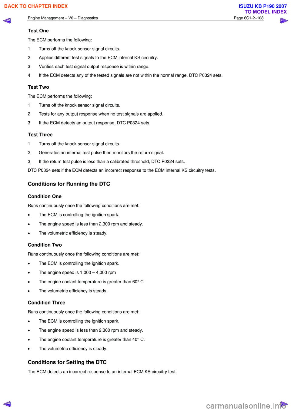
Test One
The ECM performs the following:
1 Turns off the knock sensor signal circuits.
2 Applies different test signals to the ECM internal KS circuitry.
3 Verifies each test signal output response is within range.
4 If the ECM detects any of the tested signals are not within the normal range, DTC P0324 sets.
Test Two
The ECM performs the following:
1 Turns off the knock sensor signal circuits.
2 Tests for any output response when no test signals are applied.
3 If the ECM detects an output response, DTC P0324 sets.
Test Three
1 Turns off the knock sensor signal circuits.
2 Generates an internal test pulse then monitors the return signal.
3 If the return test pulse is less than a calibrated threshold, DTC P0324 sets.
DTC P0324 sets if the ECM detects an incorrect response to the ECM internal KS circuitry tests.
Conditions for Running the DTC
Condition One
Runs continuously once the following conditions are met:
• The ECM is controlling the ignition spark.
• The engine speed is less than 2,300 rpm and steady.
• The volumetric efficiency is steady.
Condition Two
Runs continuously once the following conditions are met:
• The ECM is controlling the ignition spark.
• The engine speed is 1,000 – 4,000 rpm
• The engine coolant temperature is greater than 60 ° C.
• The volumetric efficiency is steady.
Condition Three
Runs continuously once the following conditions are met:
• The ECM is controlling the ignition spark.
• The engine speed is less than 2,300 rpm and steady.
• The engine coolant temperature is greater than 40 ° C.
• The volumetric efficiency is steady.
Conditions for Setting the DTC
The ECM detects an incorrect response to an internal ECM KS circuitry test.
BACK TO CHAPTER INDEX
TO MODEL INDEX
ISUZU KB P190 2007
Page 3387 of 6020
Engine Management – V6 – Diagnostics Page 6C1-2–109
Conditions for Clearing the DTC
DTC P0324 – Knock Sensor (KS) Module Performance is a Type B DTC. Refer to 1.4 Diagnostic Trouble Codes in
this Section, for action taken when a Type B DTC sets and conditions for clearing Type B DTC.
Additional Information
• Refer to 6C1-1 Engine Management – V6 – General Information for details of the knock sensor (KS) system
operation.
• The ECM turns off the KS signal circuits when performing the ECM internal KS circuitry tests. DTC P0324 sets if
there is a fault condition in the internal ECM KS circuitry. Therefore, the KS and the KS signal circuits are not
tested in DTC P0324 Diagnostic Table.
• For an intermittent fault condition, refer to 5.2 Intermittent Fault Conditions in this Section.
• Since fault condition in a wiring connector may trigger DTCs, always test the connectors related to this diagnostic
procedure for shorted terminals or poor wiring connection before replacing any component. Refer to 8A Electrical -
Body and Chassis for information on electrical fault diagnosis.
• To assist diagnosis, refer to 3 W iring Diagrams and Connector Charts in this Section, for the system wiring
diagram and connector charts.
Test Description
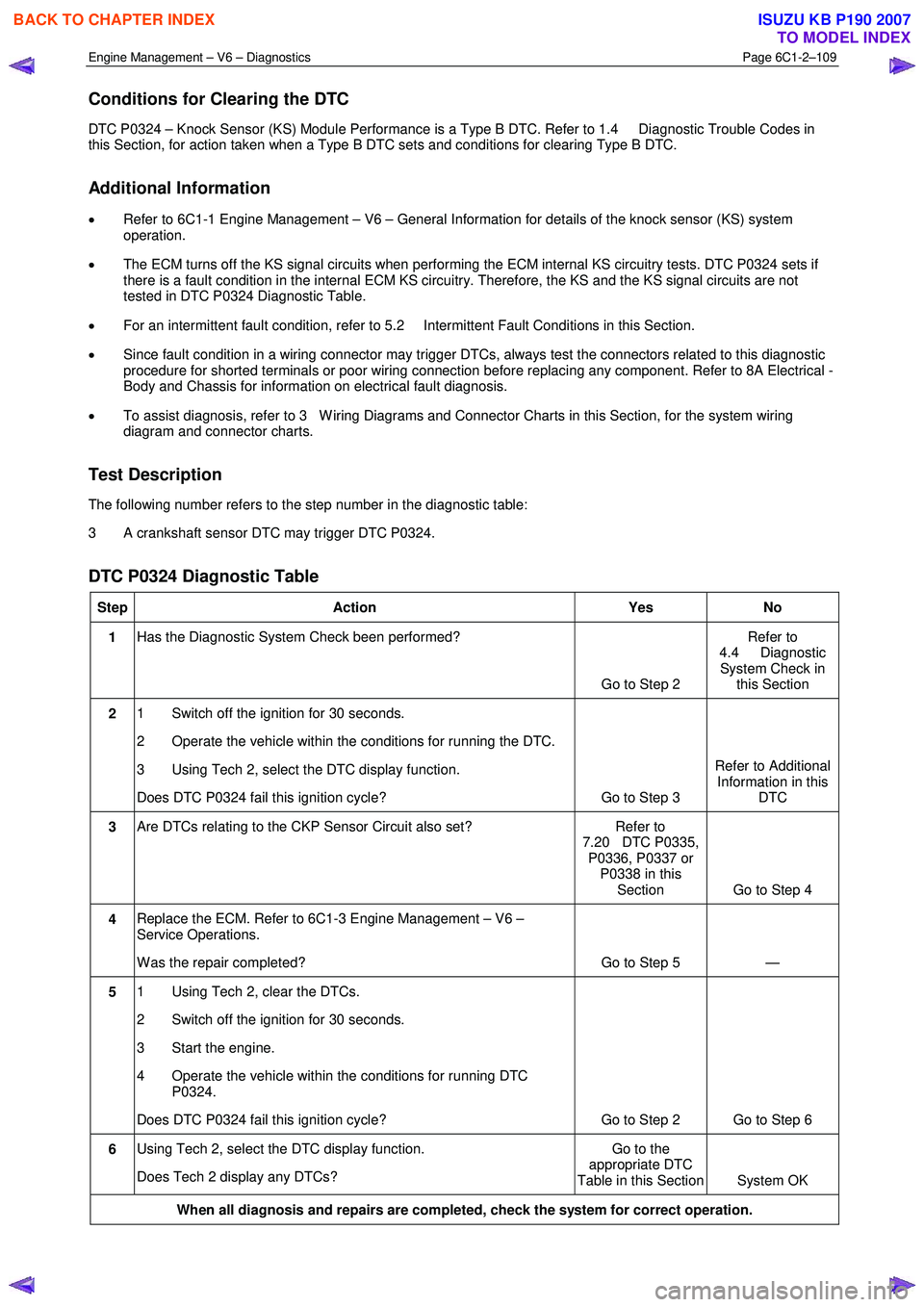
The following number refers to the step number in the diagnostic table:
3 A crankshaft sensor DTC may trigger DTC P0324.
DTC P0324 Diagnostic Table
Step Action Yes No
1 Has the Diagnostic System Check been performed?
Go to Step 2 Refer to
4.4 Diagnostic System Check in this Section
2 1 Switch off the ignition for 30 seconds.
2 Operate the vehicle within the conditions for running the DTC.
3 Using Tech 2, select the DTC display function.
Does DTC P0324 fail this ignition cycle? Go to Step 3 Refer to Additional
Information in this DTC
3 Are DTCs relating to the CKP Sensor Circuit also set? Refer to
7.20 DTC P0335, P0336, P0337 or P0338 in this Section Go to Step 4
4 Replace the ECM. Refer to 6C1-3 Engine Management – V6 –
Service Operations.
W as the repair completed? Go to Step 5 —
5 1 Using Tech 2, clear the DTCs.
2 Switch off the ignition for 30 seconds.
3 Start the engine.
4 Operate the vehicle within the conditions for running DTC P0324.
Does DTC P0324 fail this ignition cycle? Go to Step 2 Go to Step 6
6 Using Tech 2, select the DTC display function.
Does Tech 2 display any DTCs? Go to the
appropriate DTC
Table in this Section System OK
When all diagnosis and repairs are completed, check the system for correct operation.
BACK TO CHAPTER INDEX
TO MODEL INDEX
ISUZU KB P190 2007
Page 3413 of 6020
Engine Management – V6 – Diagnostics Page 6C1-2–135
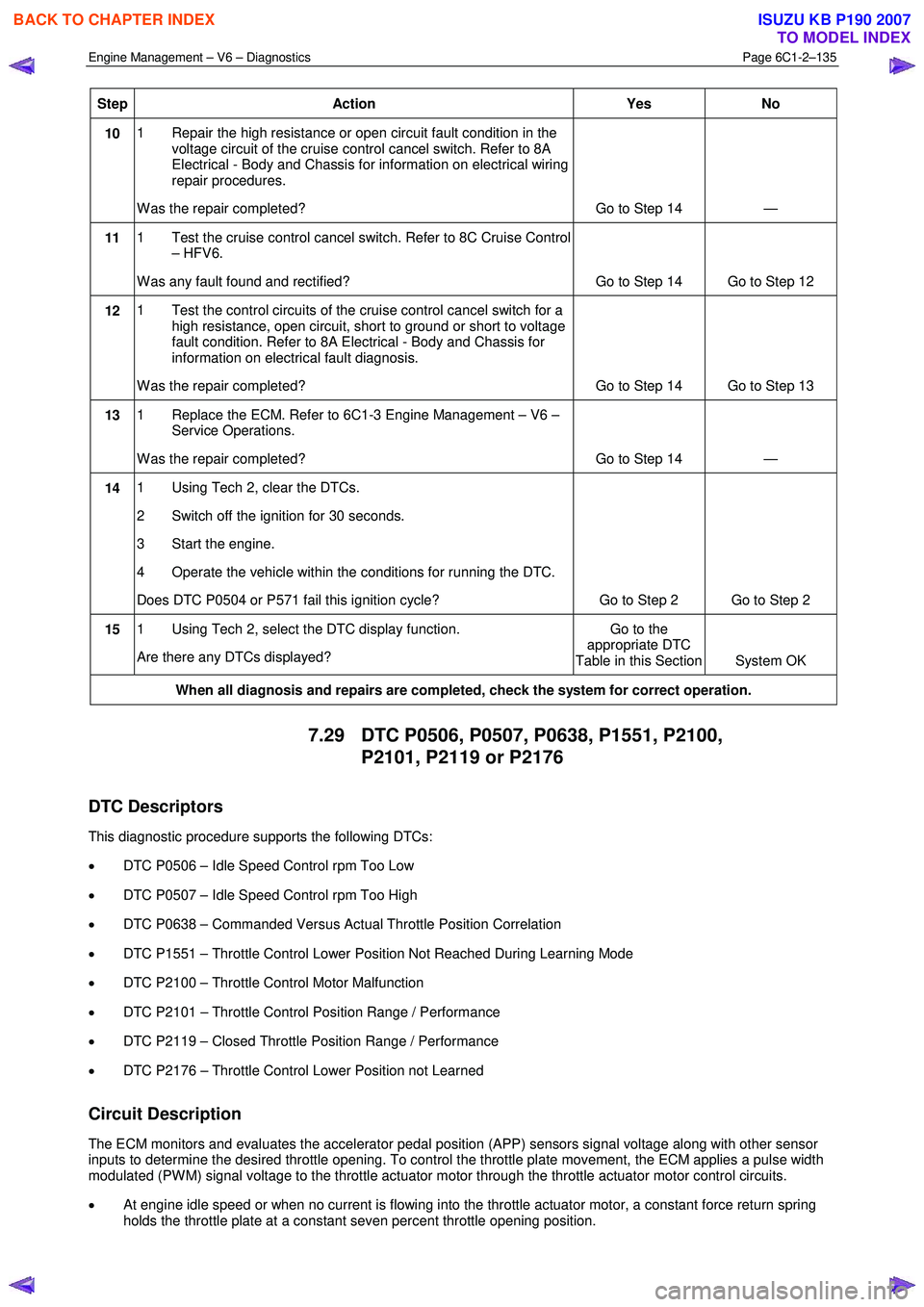
Step Action Yes No
10 1 Repair the high resistance or open circuit fault condition in the
voltage circuit of the cruise control cancel switch. Refer to 8A
Electrical - Body and Chassis for information on electrical wiring
repair procedures.
W as the repair completed? Go to Step 14 —
11 1 Test the cruise control cancel switch. Refer to 8C Cruise Control
– HFV6.
W as any fault found and rectified? Go to Step 14 Go to Step 12
12 1 Test the control circuits of the cruise control cancel switch for a
high resistance, open circuit, short to ground or short to voltage
fault condition. Refer to 8A Electrical - Body and Chassis for
information on electrical fault diagnosis.
W as the repair completed? Go to Step 14 Go to Step 13
13 1 Replace the ECM. Refer to 6C1-3 Engine Management – V6 –
Service Operations.
W as the repair completed? Go to Step 14 —
14 1 Using Tech 2, clear the DTCs.
2 Switch off the ignition for 30 seconds.
3 Start the engine.
4 Operate the vehicle within the conditions for running the DTC.
Does DTC P0504 or P571 fail this ignition cycle? Go to Step 2 Go to Step 2
15 1 Using Tech 2, select the DTC display function.
Are there any DTCs displayed? Go to the
appropriate DTC
Table in this Section System OK
When all diagnosis and repairs are completed, check the system for correct operation.
7.29 DTC P0506, P0507, P0638, P1551, P2100,
P2101, P2119 or P2176
DTC Descriptors
This diagnostic procedure supports the following DTCs:
• DTC P0506 – Idle Speed Control rpm Too Low
• DTC P0507 – Idle Speed Control rpm Too High
• DTC P0638 – Commanded Versus Actual Throttle Position Correlation
• DTC P1551 – Throttle Control Lower Position Not Reached During Learning Mode
• DTC P2100 – Throttle Control Motor Malfunction
• DTC P2101 – Throttle Control Position Range / Performance
• DTC P2119 – Closed Throttle Position Range / Performance
• DTC P2176 – Throttle Control Lower Position not Learned
Circuit Description
The ECM monitors and evaluates the accelerator pedal position (APP) sensors signal voltage along with other sensor
inputs to determine the desired throttle opening. To control the throttle plate movement, the ECM applies a pulse width
modulated (PW M) signal voltage to the throttle actuator motor through the throttle actuator motor control circuits.
• At engine idle speed or when no current is flowing into the throttle actuator motor, a constant force return spring
holds the throttle plate at a constant seven percent throttle opening position.
BACK TO CHAPTER INDEX
TO MODEL INDEX
ISUZU KB P190 2007