2007 ISUZU KB P190 turn signal
[x] Cancel search: turn signalPage 2246 of 6020
6E–76 ENGINE DRIVEABILITY AND EMISSIONS
MISCELLANEOUS TEST
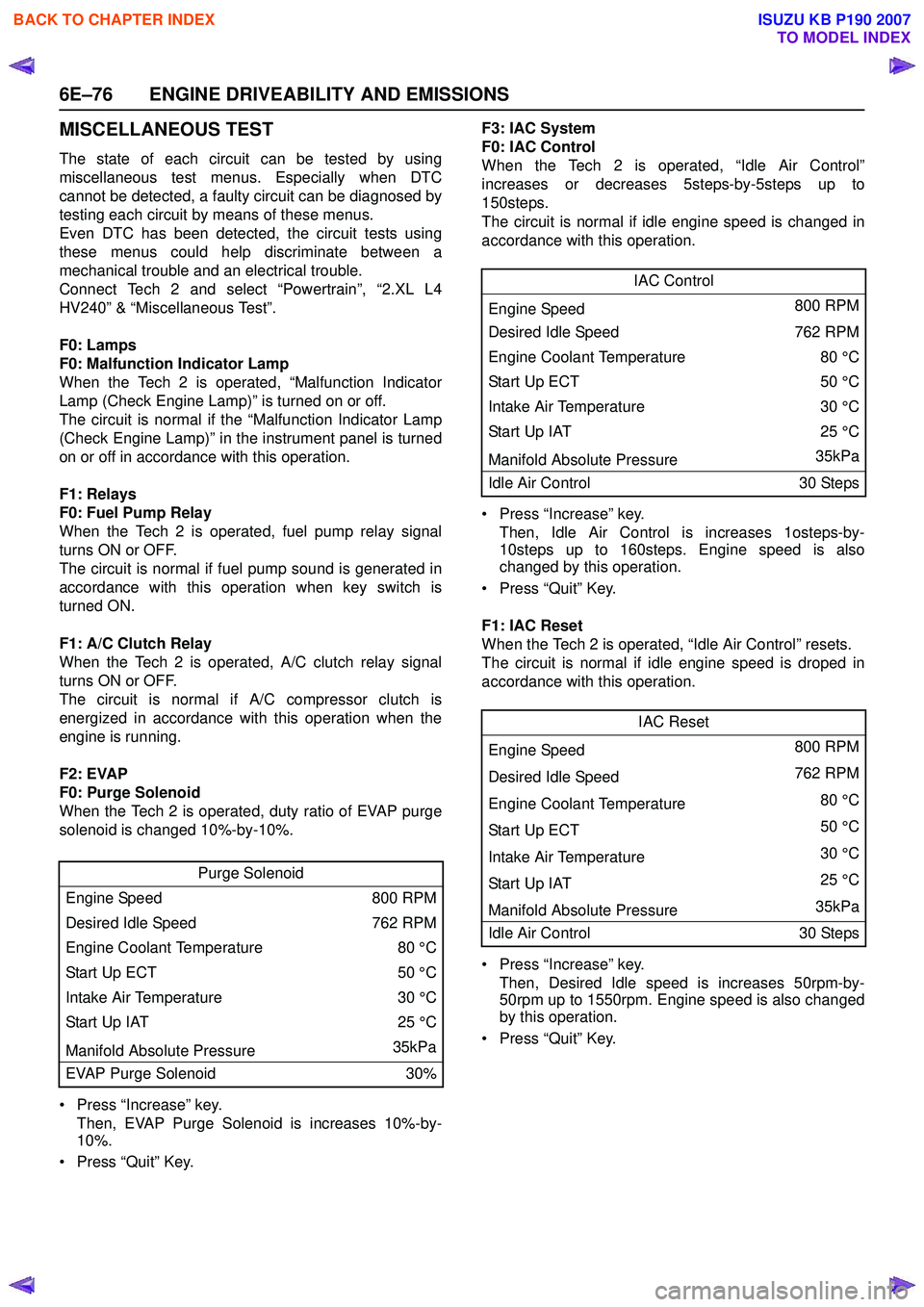
The state of each circuit can be tested by using
miscellaneous test menus. Especially when DTC
cannot be detected, a faulty circuit can be diagnosed by
testing each circuit by means of these menus.
Even DTC has been detected, the circuit tests using
these menus could help discriminate between a
mechanical trouble and an electrical trouble.
Connect Tech 2 and select “Powertrain”, “2.XL L4
HV240” & “Miscellaneous Test”.
F0: Lamps
F0: Malfunction Indicator Lamp
When the Tech 2 is operated, “Malfunction Indicator
Lamp (Check Engine Lamp)” is turned on or off.
The circuit is normal if the “Malfunction Indicator Lamp
(Check Engine Lamp)” in the instrument panel is turned
on or off in accordance with this operation.
F1: Relays
F0: Fuel Pump Relay
When the Tech 2 is operated, fuel pump relay signal
turns ON or OFF.
The circuit is normal if fuel pump sound is generated in
accordance with this operation when key switch is
turned ON.
F1: A/C Clutch Relay
When the Tech 2 is operated, A/C clutch relay signal
turns ON or OFF.
The circuit is normal if A/C compressor clutch is
energized in accordance with this operation when the
engine is running.
F2: EVAP
F0: Purge Solenoid
When the Tech 2 is operated, duty ratio of EVAP purge
solenoid is changed 10%-by-10%.
• Press “Increase” key. Then, EVAP Purge Solenoid is increases 10%-by-
10%.
• Press “Quit” Key. F3: IAC System
F0: IAC Control
When the Tech 2 is operated, “Idle Air Control”
increases or decreases 5steps-by-5steps up to
150steps.
The circuit is normal if idle engine speed is changed in
accordance with this operation.
• Press “Increase” key. Then, Idle Air Control is increases 1osteps-by-
10steps up to 160steps. Engine speed is also
changed by this operation.
• Press “Quit” Key.
F1: IAC Reset
When the Tech 2 is operated, “Idle Air Control” resets.
The circuit is normal if idle engine speed is droped in
accordance with this operation.
• Press “Increase” key. Then, Desired Idle speed is increases 50rpm-by-
50rpm up to 1550rpm. Engine speed is also changed
by this operation.
• Press “Quit” Key.
Purge Solenoid
Engine Speed 800 RPM
Desired Idle Speed 762 RPM
Engine Coolant Temperature 80 °C
Start Up ECT 50 °C
Intake Air Temperature 30 °C
Start Up IAT 25 °C
Manifold Absolute Pressure 35kPa
EVAP Purge Solenoid 30%
IAC Control
Engine Speed 800 RPM
Desired Idle Speed 762 RPM
Engine Coolant Temperature 80 °C
Sta rt U p E C T 50 °C
Intake Air Temperature 30 °C
Start Up IAT25 °C
Manifold Absolute Pressure 35kPa
Idle Air Control 30 Steps
IAC Reset
Engine Speed 800 RPM
Desired Idle Speed 762 RPM
Engine Coolant Temperature 80 °C
Sta rt U p E C T 50 °C
Intake Air Temperature 30 °C
Start Up IAT 25 °C
Manifold Absolute Pressure 35kPa
Idle Air Control 30 Steps
BACK TO CHAPTER INDEX
TO MODEL INDEX
ISUZU KB P190 2007
Page 2356 of 6020
6E–186 ENGINE DRIVEABILITY AND EMISSIONS
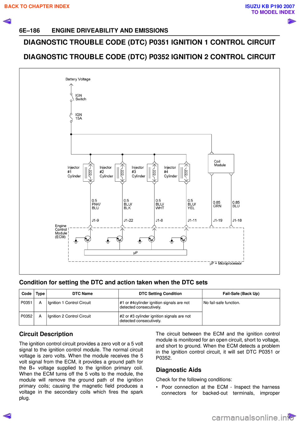
DIAGNOSTIC TROUBLE CODE (DTC) P0351 IGNITION 1 CONTROL CIRCUIT
DIAGNOSTIC TROUBLE CODE (DTC) P0352 IGNITION 2 CONTROL CIRCUIT
Condition for setting the DTC and action taken when the DTC sets
Circuit Description
The ignition control circuit provides a zero volt or a 5 volt
signal to the ignition control module. The normal circuit
voltage is zero volts. When the module receives the 5
volt signal from the ECM, it provides a ground path for
the B+ voltage supplied to the ignition primary coil.
When the ECM turns off the 5 volts to the module, the
module will remove the ground path of the ignition
primary coils; causing the magnetic field produces a
voltage in the secondary coils which fires the spark
plug. The circuit between the ECM and the ignition control
module is monitored for an open circuit, short to voltage,
and short to ground. When the ECM detects a problem
in the ignition control circuit, it will set DTC P0351 or
P0352.
Diagnostic Aids
Check for the following conditions:
• Poor connection at the ECM - Inspect the harness connectors for backed-out terminals, improper
Code Type DTC Name DTC Setting Condition Fail-Safe (Back Up)
P0351 A Ignition 1 Control Circuit #1 or #4cylinder ignition signals are not
detected consecutively. No fail-safe function.
P0352 A Ignition 2 Control Circuit #2 or #3 cylinder ignition signals are not
detected consecutively.
BACK TO CHAPTER INDEX
TO MODEL INDEX
ISUZU KB P190 2007
Page 2388 of 6020
6E–218 ENGINE DRIVEABILITY AND EMISSIONS
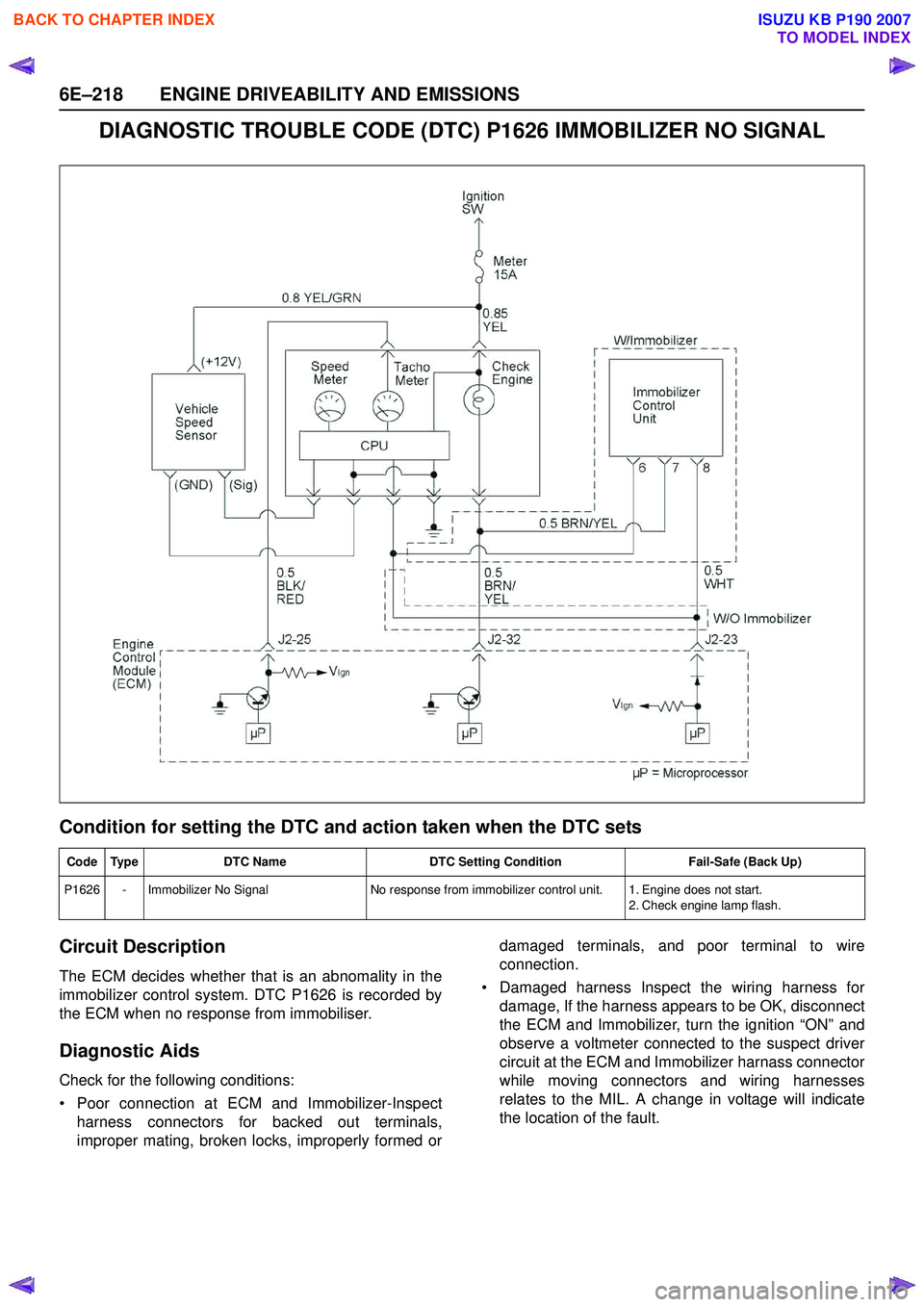
DIAGNOSTIC TROUBLE CODE (DTC) P1626 IMMOBILIZER NO SIGNAL
Condition for setting the DTC and action taken when the DTC sets
Circuit Description
The ECM decides whether that is an abnomality in the
immobilizer control system. DTC P1626 is recorded by
the ECM when no response from immobiliser.
Diagnostic Aids
Check for the following conditions:
• Poor connection at ECM and Immobilizer-Inspect harness connectors for backed out terminals,
improper mating, broken locks, improperly formed or damaged terminals, and poor terminal to wire
connection.
• Damaged harness Inspect the wiring harness for damage, If the harness appears to be OK, disconnect
the ECM and Immobilizer, turn the ignition “ON” and
observe a voltmeter connected to the suspect driver
circuit at the ECM and Immobilizer harnass connector
while moving connectors and wiring harnesses
relates to the MIL. A change in voltage will indicate
the location of the fault.
Code Type DTC Name DTC Setting Condition Fail-Safe (Back Up)
P1626 - Immobilizer No Signal No response from immobilizer control unit. 1. Engine does not start.
2. Check engine lamp flash.
BACK TO CHAPTER INDEX
TO MODEL INDEX
ISUZU KB P190 2007
Page 2392 of 6020

6E–222 ENGINE DRIVEABILITY AND EMISSIONS
DIAGNOSTIC TROUBLE CODE (DTC) P1631 IMMOBILIZER WRONG SIGNAL
Condition for setting the DTC and action taken when the DTC sets
Circuit Description
The ECM decides whether that is an abnomality in the
immobilizer control system. DTC P1631 is recorded by
the ECM when received response was not correct.
Diagnostic Aids
Check for the following conditions:
• Poor connection at ECM and Immobilizer-Inspect harness connectors for backed out terminals,
improper mating, broken locks, improperly formed or damaged terminals, and poor terminal to wire
connection.
• Damaged harness-Inspect the wiring harness for damage, If the harness appears to be OK, disconnect
the ECM and Immobilizer, turn the ignition “ON” and
observe a voltmeter connected to the suspect driver
circuit at the ECM and Immobilizer harnass connector
while moving connectors and wiring harnesses
relates to the MIL. A change in voltage will indicate
the location of the fault.
Code Type DTC Name DTC Setting Condition Fail-Safe (Back Up)
P1631 - Immobilizer Wrong Signal Received response is not correct.1. Engine does not start.
2. Check engine lamp flash.
BACK TO CHAPTER INDEX
TO MODEL INDEX
ISUZU KB P190 2007
Page 3251 of 6020
Engine Management – V6 – General Information Page 6C1-1–9
3 System Operation
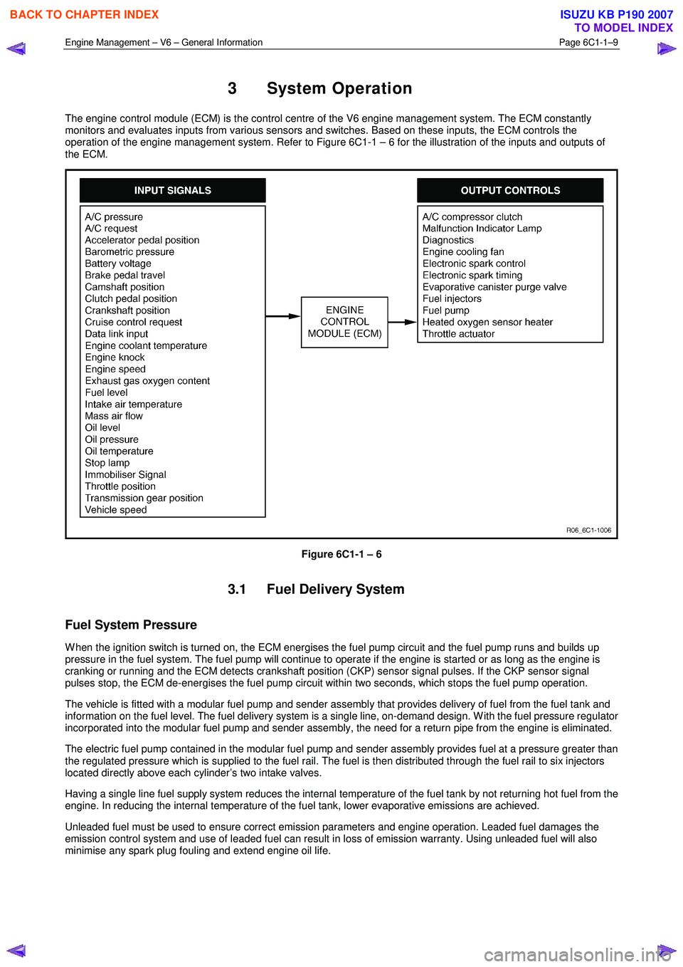
The engine control module (ECM) is the control centre of the V6 engine management system. The ECM constantly
monitors and evaluates inputs from various sensors and switches. Based on these inputs, the ECM controls the
operation of the engine management system. Refer to Figure 6C1-1 – 6 for the illustration of the inputs and outputs of
the ECM.
Figure 6C1-1 – 6
3.1 Fuel Delivery System
Fuel System Pressure
W hen the ignition switch is turned on, the ECM energises the fuel pump circuit and the fuel pump runs and builds up
pressure in the fuel system. The fuel pump will continue to operate if the engine is started or as long as the engine is
cranking or running and the ECM detects crankshaft position (CKP) sensor signal pulses. If the CKP sensor signal
pulses stop, the ECM de-energises the fuel pump circuit within two seconds, which stops the fuel pump operation.
The vehicle is fitted with a modular fuel pump and sender assembly that provides delivery of fuel from the fuel tank and
information on the fuel level. The fuel delivery system is a single line, on-demand design. W ith the fuel pressure regulator
incorporated into the modular fuel pump and sender assembly, the need for a return pipe from the engine is eliminated.
The electric fuel pump contained in the modular fuel pump and sender assembly provides fuel at a pressure greater than
the regulated pressure which is supplied to the fuel rail. The fuel is then distributed through the fuel rail to six injectors
located directly above each cylinder’s two intake valves.
Having a single line fuel supply system reduces the internal temperature of the fuel tank by not returning hot fuel from the
engine. In reducing the internal temperature of the fuel tank, lower evaporative emissions are achieved.
Unleaded fuel must be used to ensure correct emission parameters and engine operation. Leaded fuel damages the
emission control system and use of leaded fuel can result in loss of emission warranty. Using unleaded fuel will also
minimise any spark plug fouling and extend engine oil life.
BACK TO CHAPTER INDEX
TO MODEL INDEX
ISUZU KB P190 2007
Page 3252 of 6020
Engine Management – V6 – General Information Page 6C1-1–10
Fuel Injection System
Each cylinder of the V6 engine is fitted with one fuel injector. The engine control relay applies ignition positive voltage to
the fuel injector ignition circuit. The ECM controls the operation of the fuel injectors by applying a pulse width modulated
(PW M) ground to the fuel injector control circuit to control each fuel injector on-time.
W hile the engine is running, the ECM constantly monitors the various inputs and recalculates the appropriate on-time for
each injector. The calculation is based on the following:
• The injector flow rate,
• Mass of fuel passed by the energised injector per unit of time,
• The desired air / fuel ratio, and
• Actual air mass in each cylinder.
The ECM calculates the duration of the fuel injector on-time to deliver the correct amount of fuel for optimum drivability
and emission control. The period of time the fuel injector is energised is called the injector on-time and is measured in
milliseconds (thousandths of a second).
The V6 engine uses the sequential fuel injection system. Each fuel injector is energised individually at the correct
moment during its firing stroke as the cylinder’s intake valves are closing to provide enough time for the fuel to atomise
completely and mix with the intake air.
Short Term Fuel Trim
The short term fuel trim (STFT) represents the duration of the fuel injector on-time as calculated by the ECM, while the
ECM is in Closed Loop mode. The STFT allows the ECM to calculate the fuel injector on-time based on the heated
oxygen sensor (HO2S) signal input to the ECM. Therefore, the STFT is disabled when the ECM is in Open Loop mode.
• If the air / fuel mixture in the exhaust is balanced (lambda = 1) or when the STFT is disabled, the STFT value is 0%.
• W hen the HO2S sends an input signal to the ECM indicating the air / fuel mixture is rich, the STFT will be less than
0%, which indicates the ECM is decreasing the fuel injector on-time to reduce the amount of fuel in the air / fuel
mixture.
• W hen the HO2S sends an input signal to the ECM indicating the air / fuel mixture is lean, the STFT will be greater
than 0%, which indicates the ECM is increasing the fuel injector on-time to increase the amount of fuel in the air /
fuel mixture.
The percentage values of the STFT range from –25% to +25% and are directly proportional to the duration of the fuel
injector on-time.
Long Term Fuel Trim
The ECM stores the long term fuel trim (LTFT) in its memory to adjust the fuel injector on-time according to the long term
changes or deterioration in the engine components. The normal LTFT value is 0%.
The following describes the LTFT operation when the engine air filter is dirty that causes a restricted intake airflow fault
condition:
1 The HO2S sends an input signal to the ECM the air / fuel mixture is rich because of the reduced airflow. The STFT may reduce to a value of –10%, which decreases the fuel injector on-time to reduce the amount of fuel in the air /
fuel mixture supplied to the engine.
W ithout the use of the LTFT, the restricted airflow caused by the dirty air filter may reduce the STFT value to –10% until the air filter is replaced. This will decrease the range of negative adjustment available to the STFT to
compensate for other factors.
2 W hen the ECM detects the STFT has remained at –10% for a specific period, the ECM switches to the LTFT. The LTFT adjusts the duration of the fuel injector on-time until the air / fuel mixture in the exhaust is balanced (lambda =
1) and the STFT value returns to 0%.
3 The ECM stores this Long Term FT value in its memory, which is used to calculate the base fuel injector on-time.
The percentage values of the Long Term FT range from –100% to +100%. If the ECM detects the LTFT values are
outside the specified percentage range for a predetermined period, the ECM will set a Diagnostic Trouble Code and
switch to Open Loop mode.
BACK TO CHAPTER INDEX
TO MODEL INDEX
ISUZU KB P190 2007
Page 3253 of 6020
Engine Management – V6 – General Information Page 6C1-1–11
3.2 Air / Fuel Control System
The engine control module (ECM) controls the amount of air and fuel delivered into each of the engine cylinders. Based
on the various ECM inputs, the ECM switches to the following air / fuel control system mode to provide the optimum air /
fuel ratio under all engine operating conditions.
Starting Mode
W hen the ignition switch is moved to the START position and the engine begins to turn, a prime pulse may be injected to
speed starting. As soon as the ECM receives an input signal from the camshaft position (CMP) and crankshaft position
(CKP) sensor and determines which cylinder is in the firing stroke, the ECM applies a pulse width modulated (PW M)
ground to the injector control circuit. The ECM monitors mass air flow, intake air temperature, engine coolant
temperature, and throttle position to determine the required fuel injector on-time required for starting the engine.
Run Mode
The engine switches to run mode when the engine speed reaches 480 rpm after being started. The run mode has two
sub-modes called Open Loop and Closed Loop.
Open Loop Mode
The heated oxygen sensor (HO2S) does not produce a usable signal voltage output until it reaches operating
temperature. Therefore, while the HO2S is below its operating temperature, the ECM switches to open loop mode.
In open loop, the ECM ignores the signals from the HO2S and calculates the required injector pulse width based
primarily on inputs from the mass air flow (MAF), intake air temperature (IAT), and engine coolant temperature sensors.
The system will stay in the open loop mode until the HO2S produce a usable output.
Closed Loop Mode
Once the HO2S reaches operating temperature and starts producing its own signal voltage output, the ECM switches to
the closed loop mode.
In closed loop mode, the ECM initially calculates injector pulse width based on the same sensors used in open loop, and
additionally the ECM uses the oxygen sensor signals to modify and fine tune the fuel pulse width calculations to precisely
maintain the ideal 14.7 to 1 air / fuel ratio.
Acceleration Mode
The ECM monitors and calculates input signals from the accelerator pedal position (APP) and MAF sensor signals to
determine when the vehicle is being accelerated. If the ECM detects the accelerator pedal is depressed and there is a
demand for the vehicle to accelerate, the ECM switches to acceleration mode. In acceleration mode, the ECM increases
the fuel injector on-time to provide more fuel accordingly.
Deceleration Mode
The ECM monitors and calculates input signals from the APP and MAF sensor signals to determine when the vehicle is
being decelerated. If the ECM detects the vehicle is decelerating, the ECM switches to deceleration mode. In
deceleration mode, the ECM decreases the fuel injector on-time, or disables the fuel injectors for short periods, to reduce
exhaust emissions and improve fuel economy.
Fuel Shut-off Mode
To protect the engine from damage or to improve the vehicle's driveability, the ECM switches to the fuel shut-off mode. In
fuel shut-off mode, the ECM performs the following:
• The ECM disables the six fuel injectors under the following conditions:
− Ignition off – to prevent engine dieseling,
− Ignition on but no ignition reference signal – prevents flooding or backfiring,
− At high engine speed – greater than the red line (rev limiter),
− At high vehicle speed – greater than the rated tire speed (vehicle speed limiter), or
− Extended high speed closed throttle coast-down – reduces engine emissions and increases engine braking.
• The ECM selectively disables the appropriate number of fuel injectors when torque management has been enabled.
BACK TO CHAPTER INDEX
TO MODEL INDEX
ISUZU KB P190 2007
Page 3257 of 6020
Engine Management – V6 – General Information Page 6C1-1–15
W hen the cruise control ON-OFF switch, located on the right hand side of the dash panel, is pressed, the PIM, on
receiving the input from the switch, turns on the cruise ON-OFF switch warning lamp to inform the user that the cruise
control has been engaged.
W hen the cruise control switch assembly is pressed to SET/COAST, the PIM on receiving the input, sends a signal via
the serial data bus to the ECM. Providing the pre-conditions for cruise control operation have been met, the ECM
activates cruise control and commands the PIM to turn on the instrument cluster cruise set warning lamp, to inform the
user that cruise control is active. The ECM receives all the various inputs required to maintain the correct speed and then
controls the throttle plate depending on the load on the engine (ascending or descending hills, etc).
The cruise control is deactivated by either pressing the brake pedal, clutch pedal, cruise CANCEL or by the cruise control
ON-OFF button. In each of these instances, the ECM receives an input when any of these switches are activated. For
further information on the cruise control system, refer to 8C Cruise Control – HFV6.
3.7 Brake Torque Management
Brake torque management places limits on engine torque when the brakes are applied, regardless of the accelerator
pedal position (APP). The conditions under which brake torque management occur are as follows:
• The accelerator has been depressed before the brakes are applied,
• The brakes are applied and the ECM receives an input from the stop lamp switch,
• Vehicle speed is greater than 5 km/h,
• Engine speed is greater than 1200 rpm and
• Conditions exist for greater than 2.5 seconds.
W hen brake torque management has been implemented, the torque is reduced by altering the throttle plate opening by
25%. The ECM will monitor the rate at which the vehicle is slowing and adjust the throttle plate opening accordingly.
3.8 Emission Control Systems
Evaporative Emission Control System
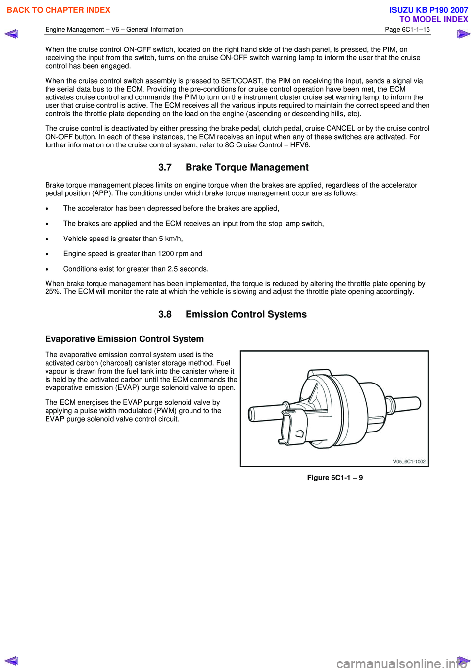
The evaporative emission control system used is the
activated carbon (charcoal) canister storage method. Fuel
vapour is drawn from the fuel tank into the canister where it
is held by the activated carbon until the ECM commands the
evaporative emission (EVAP) purge solenoid valve to open.
The ECM energises the EVAP purge solenoid valve by
applying a pulse width modulated (PW M) ground to the
EVAP purge solenoid valve control circuit.
Figure 6C1-1 – 9
BACK TO CHAPTER INDEX
TO MODEL INDEX
ISUZU KB P190 2007