2007 ISUZU KB P190 turn signal
[x] Cancel search: turn signalPage 1931 of 6020
6E-314 ENGINE CONTROL SYSTEM (4JK1/4JJ1)
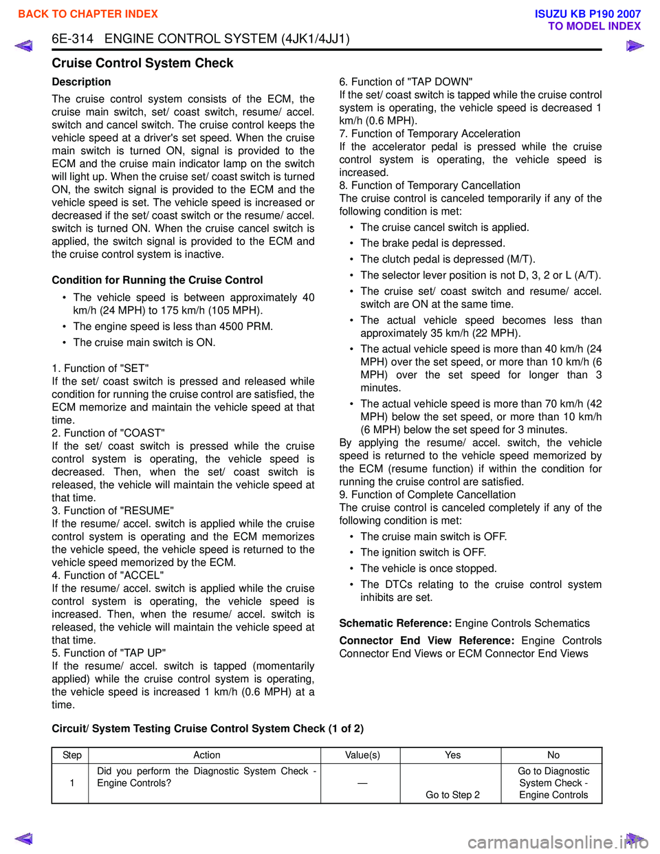
Cruise Control System Check
Description
The cruise control system consists of the ECM, the
cruise main switch, set/ coast switch, resume/ accel.
switch and cancel switch. The cruise control keeps the
vehicle speed at a driver's set speed. When the cruise
main switch is turned ON, signal is provided to the
ECM and the cruise main indicator lamp on the switch
will light up. When the cruise set/ coast switch is turned
ON, the switch signal is provided to the ECM and the
vehicle speed is set. The vehicle speed is increased or
decreased if the set/ coast switch or the resume/ accel.
switch is turned ON. When the cruise cancel switch is
applied, the switch signal is provided to the ECM and
the cruise control system is inactive.
Condition for Running the Cruise Control • The vehicle speed is between approximately 40 km/h (24 MPH) to 175 km/h (105 MPH).
• The engine speed is less than 4500 PRM.
• The cruise main switch is ON.
1. Function of "SET"
If the set/ coast switch is pressed and released while
condition for running the cruise control are satisfied, the
ECM memorize and maintain the vehicle speed at that
time.
2. Function of "COAST"
If the set/ coast switch is pressed while the cruise
control system is operating, the vehicle speed is
decreased. Then, when the set/ coast switch is
released, the vehicle will maintain the vehicle speed at
that time.
3. Function of "RESUME"
If the resume/ accel. switch is applied while the cruise
control system is operating and the ECM memorizes
the vehicle speed, the vehicle speed is returned to the
vehicle speed memorized by the ECM.
4. Function of "ACCEL"
If the resume/ accel. switch is applied while the cruise
control system is operating, the vehicle speed is
increased. Then, when the resume/ accel. switch is
released, the vehicle will maintain the vehicle speed at
that time.
5. Function of "TAP UP"
If the resume/ accel. switch is tapped (momentarily
applied) while the cruise control system is operating,
the vehicle speed is increased 1 km/h (0.6 MPH) at a
time. 6. Function of "TAP DOWN"
If the set/ coast switch is tapped while the cruise control
system is operating, the vehicle speed is decreased 1
km/h (0.6 MPH).
7. Function of Temporary Acceleration
If the accelerator pedal is pressed while the cruise
control system is operating, the vehicle speed is
increased.
8. Function of Temporary Cancellation
The cruise control is canceled temporarily if any of the
following condition is met:
• The cruise cancel switch is applied.
• The brake pedal is depressed.
• The clutch pedal is depressed (M/T).
• The selector lever position is not D, 3, 2 or L (A/T).
• The cruise set/ coast switch and resume/ accel. switch are ON at the same time.
• The actual vehicle speed becomes less than approximately 35 km/h (22 MPH).
• The actual vehicle speed is more than 40 km/h (24 MPH) over the set speed, or more than 10 km/h (6
MPH) over the set speed for longer than 3
minutes.
• The actual vehicle speed is more than 70 km/h (42 MPH) below the set speed, or more than 10 km/h
(6 MPH) below the set speed for 3 minutes.
By applying the resume/ accel. switch, the vehicle
speed is returned to the vehicle speed memorized by
the ECM (resume function) if within the condition for
running the cruise control are satisfied.
9. Function of Complete Cancellation
The cruise control is canceled completely if any of the
following condition is met:
• The cruise main switch is OFF.
• The ignition switch is OFF.
• The vehicle is once stopped.
• The DTCs relating to the cruise control system inhibits are set.
Schematic Reference: Engine Controls Schematics
Connector End View Reference: Engine Controls
Connector End Views or ECM Connector End Views
Circuit/ System Testing Cruise Control System Check (1 of 2)
Step Action Value(s)Yes No
1 Did you perform the Diagnostic System Check -
Engine Controls? —
Go to Step 2 Go to Diagnostic
System Check -
Engine Controls
BACK TO CHAPTER INDEX
TO MODEL INDEX
ISUZU KB P190 2007
Page 1933 of 6020
6E-316 ENGINE CONTROL SYSTEM (4JK1/4JJ1)
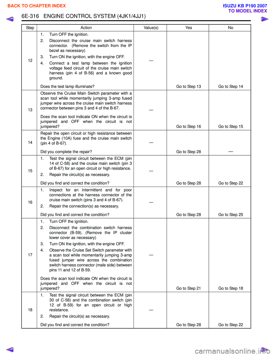
121. Turn OFF the ignition.
2. Disconnect the cruise main switch harness connector. (Remove the switch from the IP
bezel as necessary)
3. Turn ON the ignition, with the engine OFF.
4. Connect a test lamp between the ignition voltage feed circuit of the cruise main switch
harness (pin 4 of B-56) and a known good
ground.
Does the test lamp illuminate? —
Go to Step 13 Go to Step 14
13 Observe the Cruise Main Switch parameter with a
scan tool while momentarily jumping 3-amp fused
jumper wire across the cruise main switch harness
connector between pins 3 and 4 of the B-67.
Does the scan tool indicate ON when the circuit is
jumpered and OFF when the circuit is not
jumpered? —
Go to Step 16 Go to Step 15
14 Repair the open circuit or high resistance between
the Engine (10A) fuse and the cruise main switch
(pin 4 of B-67).
Did you complete the repair? —
Go to Step 28
—
151. Test the signal circuit between the ECM (pin
14 of C-58) and the cruise main switch (pin 3
of B-67) for an open circuit or high resistance.
2. Repair the circuit(s) as necessary.
Did you find and correct the condition? —
Go to Step 28 Go to Step 22
16 1. Inspect for an intermittent and for poor
connections at the harness connector of the
cruise main switch (pins 3 and 4 of B-67).
2. Repair the connection(s) as necessary.
Did you find and correct the condition? —
Go to Step 28 Go to Step 25
17 1. Turn OFF the ignition.
2. Disconnect the combination switch harness connector (B-59). (Remove the IP cluster
lower cover as necessary)
3. Turn ON the ignition, with the engine OFF.
4. Observe the Cruise Set Switch parameter with a scan tool while momentarily jumping 3-amp
fused jumper wire across the combination
switch harness connector (male side) between
pins 11 and 12 of B-59.
Does the scan tool indicate ON when the circuit is
jumpered and OFF when the circuit is not
jumpered? —
Go to Step 21 Go to Step 18
18 1. Test the signal circuit between the ECM (pin
30 of C-58) and the combination switch (pin
12 of B-59) for an open circuit or high
resistance.
2. Repair the circuit(s) as necessary.
Did you find and correct the condition? —
Go to Step 28 Go to Step 22
Step
Action Value(s)Yes No
BACK TO CHAPTER INDEX
TO MODEL INDEX
ISUZU KB P190 2007
Page 1934 of 6020
ENGINE CONTROL SYSTEM (4JK1/4JJ1) 6E-317
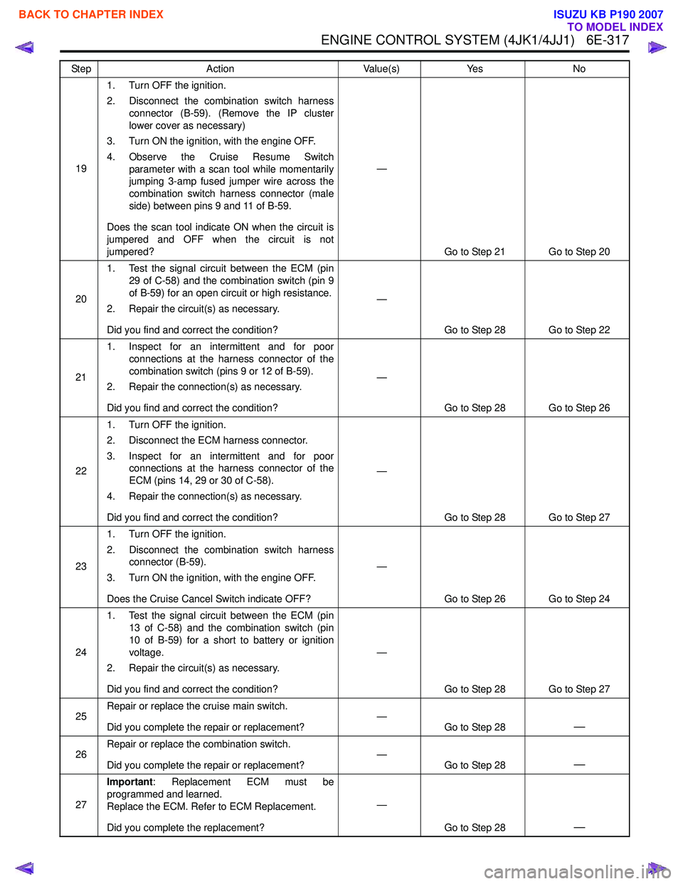
191. Turn OFF the ignition.
2. Disconnect the combination switch harness connector (B-59). (Remove the IP cluster
lower cover as necessary)
3. Turn ON the ignition, with the engine OFF.
4. Observe the Cruise Resume Switch parameter with a scan tool while momentarily
jumping 3-amp fused jumper wire across the
combination switch harness connector (male
side) between pins 9 and 11 of B-59.
Does the scan tool indicate ON when the circuit is
jumpered and OFF when the circuit is not
jumpered? —
Go to Step 21 Go to Step 20
20 1. Test the signal circuit between the ECM (pin
29 of C-58) and the combination switch (pin 9
of B-59) for an open circuit or high resistance.
2. Repair the circuit(s) as necessary.
Did you find and correct the condition? —
Go to Step 28 Go to Step 22
21 1. Inspect for an intermittent and for poor
connections at the harness connector of the
combination switch (pins 9 or 12 of B-59).
2. Repair the connection(s) as necessary.
Did you find and correct the condition? —
Go to Step 28 Go to Step 26
22 1. Turn OFF the ignition.
2. Disconnect the ECM harness connector.
3. Inspect for an intermittent and for poor connections at the harness connector of the
ECM (pins 14, 29 or 30 of C-58).
4. Repair the connection(s) as necessary.
Did you find and correct the condition? —
Go to Step 28 Go to Step 27
23 1. Turn OFF the ignition.
2. Disconnect the combination switch harness connector (B-59).
3. Turn ON the ignition, with the engine OFF.
Does the Cruise Cancel Switch indicate OFF? —
Go to Step 26 Go to Step 24
24 1. Test the signal circuit between the ECM (pin
13 of C-58) and the combination switch (pin
10 of B-59) for a short to battery or ignition
voltage.
2. Repair the circuit(s) as necessary.
Did you find and correct the condition? —
Go to Step 28 Go to Step 27
25 Repair or replace the cruise main switch.
Did you complete the repair or replacement? —
Go to Step 28
—
26Repair or replace the combination switch.
Did you complete the repair or replacement? —
Go to Step 28—
27Important
: Replacement ECM must be
programmed and learned.
Replace the ECM. Refer to ECM Replacement.
Did you complete the replacement? —
Go to Step 28
—
Step Action Value(s)Yes No
BACK TO CHAPTER INDEX
TO MODEL INDEX
ISUZU KB P190 2007
Page 1968 of 6020
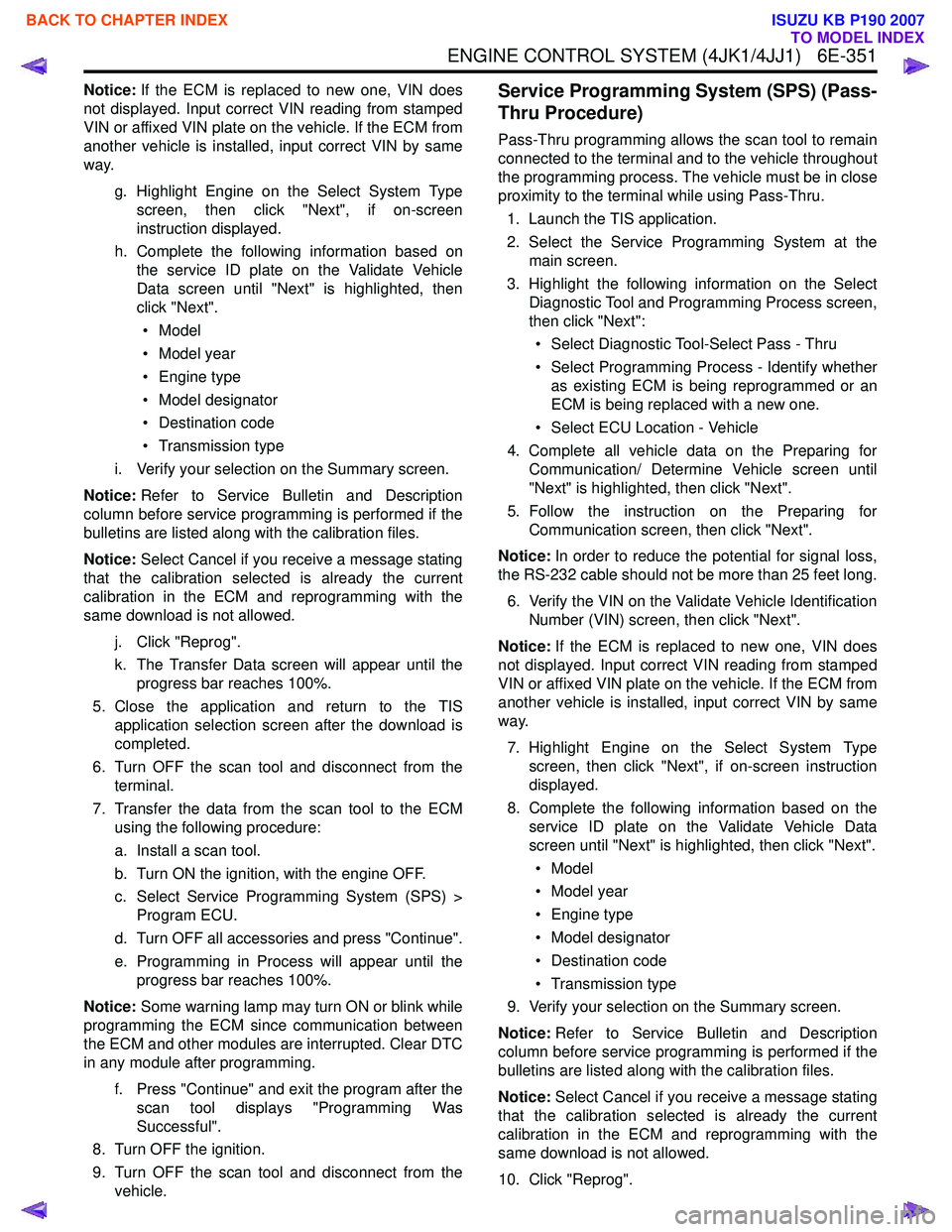
ENGINE CONTROL SYSTEM (4JK1/4JJ1) 6E-351
Notice:If the ECM is replaced to new one, VIN does
not displayed. Input correct VIN reading from stamped
VIN or affixed VIN plate on the vehicle. If the ECM from
another vehicle is installed, input correct VIN by same
way.
g. Highlight Engine on the Select System Typescreen, then click "Next", if on-screen
instruction displayed.
h. Complete the following information based on the service ID plate on the Validate Vehicle
Data screen until "Next" is highlighted, then
click "Next".
• Model
• Model year
• Engine type
• Model designator
• Destination code
• Transmission type
i. Verify your selection on the Summary screen.
Notice: Refer to Service Bulletin and Description
column before service programming is performed if the
bulletins are listed along with the calibration files.
Notice: Select Cancel if you receive a message stating
that the calibration selected is already the current
calibration in the ECM and reprogramming with the
same download is not allowed.
j. Click "Reprog".
k. The Transfer Data screen will appear until the progress bar reaches 100%.
5. Close the application and return to the TIS application selection screen after the download is
completed.
6. Turn OFF the scan tool and disconnect from the terminal.
7. Transfer the data from the scan tool to the ECM using the following procedure:
a. Install a scan tool.
b. Turn ON the ignition, with the engine OFF.
c. Select Service Programming System (SPS) > Program ECU.
d. Turn OFF all accessories and press "Continue".
e. Programming in Process will appear until the progress bar reaches 100%.
Notice: Some warning lamp may turn ON or blink while
programming the ECM since communication between
the ECM and other modules are interrupted. Clear DTC
in any module after programming.
f. Press "Continue" and exit the program after thescan tool displays "Programming Was
Successful".
8. Turn OFF the ignition.
9. Turn OFF the scan tool and disconnect from the vehicle.Service Programming System (SPS) (Pass-
Thru Procedure)
Pass-Thru programming allows the scan tool to remain
connected to the terminal and to the vehicle throughout
the programming process. The vehicle must be in close
proximity to the terminal while using Pass-Thru.
1. Launch the TIS application.
2. Select the Service Programming System at the main screen.
3. Highlight the following information on the Select Diagnostic Tool and Programming Process screen,
then click "Next":
• Select Diagnostic Tool-Select Pass - Thru
• Select Programming Process - Identify whether as existing ECM is being reprogrammed or an
ECM is being replaced with a new one.
• Select ECU Location - Vehicle
4. Complete all vehicle data on the Preparing for Communication/ Determine Vehicle screen until
"Next" is highlighted, then click "Next".
5. Follow the instruction on the Preparing for Communication screen, then click "Next".
Notice: In order to reduce the potential for signal loss,
the RS-232 cable should not be more than 25 feet long.
6. Verify the VIN on the Validate Vehicle Identification Number (VIN) screen, then click "Next".
Notice: If the ECM is replaced to new one, VIN does
not displayed. Input correct VIN reading from stamped
VIN or affixed VIN plate on the vehicle. If the ECM from
another vehicle is installed, input correct VIN by same
way.
7. Highlight Engine on the Select System Type screen, then click "Next", if on-screen instruction
displayed.
8. Complete the following information based on the service ID plate on the Validate Vehicle Data
screen until "Next" is highlighted, then click "Next".
• Model
• Model year
• Engine type
• Model designator
• Destination code
• Transmission type
9. Verify your selection on the Summary screen.
Notice: Refer to Service Bulletin and Description
column before service programming is performed if the
bulletins are listed along with the calibration files.
Notice: Select Cancel if you receive a message stating
that the calibration selected is already the current
calibration in the ECM and reprogramming with the
same download is not allowed.
10. Click "Reprog".
BACK TO CHAPTER INDEX
TO MODEL INDEX
ISUZU KB P190 2007
Page 1971 of 6020
6E-354 ENGINE CONTROL SYSTEM (4JK1/4JJ1)
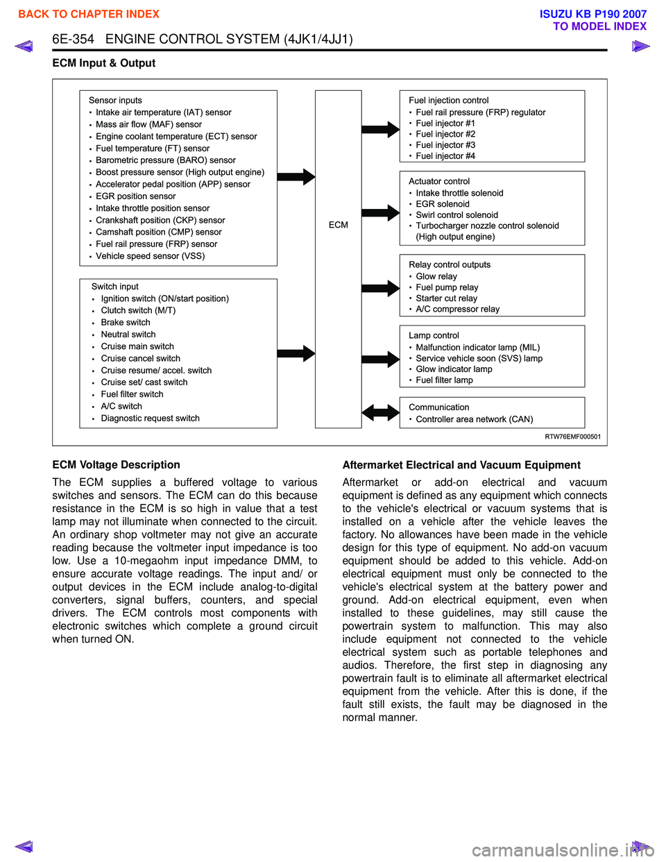
ECM Input & Output
ECM Voltage Description
The ECM supplies a buffered voltage to various
switches and sensors. The ECM can do this because
resistance in the ECM is so high in value that a test
lamp may not illuminate when connected to the circuit.
An ordinary shop voltmeter may not give an accurate
reading because the voltmeter input impedance is too
low. Use a 10-megaohm input impedance DMM, to
ensure accurate voltage readings. The input and/ or
output devices in the ECM include analog-to-digital
converters, signal buffers, counters, and special
drivers. The ECM controls most components with
electronic switches which complete a ground circuit
when turned ON. Aftermarket Electrical and Vacuum Equipment
Aftermarket or add-on electrical and vacuum
equipment is defined as any equipment which connects
to the vehicle's electrical or vacuum systems that is
installed on a vehicle after the vehicle leaves the
factory. No allowances have been made in the vehicle
design for this type of equipment. No add-on vacuum
equipment should be added to this vehicle. Add-on
electrical equipment must only be connected to the
vehicle's electrical system at the battery power and
ground. Add-on electrical equipment, even when
installed to these guidelines, may still cause the
powertrain system to malfunction. This may also
include equipment not connected to the vehicle
electrical system such as portable telephones and
audios. Therefore, the first step in diagnosing any
powertrain fault is to eliminate all aftermarket electrical
equipment from the vehicle. After this is done, if the
fault still exists, the fault may be diagnosed in the
normal manner.
RTW76EMF000501
Sensor inputs
· Intake air temperature (IAT) sensor
· Mass air flow (MAF) sensor
· Engine coolant temperature (ECT) sensor
· Fuel temperature (FT) sensor
· Barometric pressure (BARO) sensor
· Boost pressure sensor (High output engine)
· Accelerator pedal position (APP) sensor
· EGR position sensor
· Intake throttle position sensor
· Crankshaft position (CKP) sensor
· Camshaft position (CMP) sensor
· Fuel rail pressure (FRP) sensor
· Vehicle speed sensor (VSS)
Switch input
· Ignition switch (ON/start position)
· Clutch switch (M/T)
· Brake switch
· Neutral switch
· Cruise main switch
· Cruise cancel switch
· Cruise resume/ accel. switch
· Cruise set/ cast switch
· Fuel filter switch
· A/C switch
· Diagnostic request switch
Fuel injection control
· Fuel rail pressure (FRP) regulator
· Fuel injector #1
· Fuel injector #2
· Fuel injector #3
· Fuel injector #4
Relay control outputs
· Glow relay
· Fuel pump relay
· Starter cut relay
· A/C compressor relay
Lamp control
· Malfunction indicator lamp (MIL)
· Service vehicle soon (SVS) lamp
· Glow indicator lamp
· Fuel filter lamp
Communication
· Controller area network (CAN)
Actuator control
· Intake throttle solenoid
· EGR solenoid
· Swirl control solenoid
· Turbocharger nozzle control solenoid
(High output engine)ECM
BACK TO CHAPTER INDEX
TO MODEL INDEX
ISUZU KB P190 2007
Page 1980 of 6020
ENGINE CONTROL SYSTEM (4JK1/4JJ1) 6E-363
Along with the employment of a common rail type
electronic control fuel injection system, the fuel rail is
provided to store high pressure fuel between supply
pump and injectors. A pressure sensor and a pressure
limiter are installed on the fuel rail. The pressure sensor
detects the fuel pressure inside the fuel rail and sends
its signal to the ECM. Based on this signal, the ECM
controls the fuel pressure inside the fuel rail via the fuel
rail pressure (FRP) regulator of the supply pump. The
pressure limiter opens the valve mechanically to relieve
the pressure when the fuel pressure inside the fuel rail
is excessive.
Fuel Rail Pressure Sensor
The FRP sensor is installed to the fuel rail and it
detects the fuel pressure in the fuel rail, converts the
pressure into a voltage signal, and sends the signal to
the ECM. The ECM monitors the FRP sensor signal
voltage. Higher fuel rail pressure provides higher signal
voltage while lower pressure provides lower signal
voltage. The ECM calculates actual fuel rail pressure
(fuel pressure) from the voltage signal and uses the
result in fuel injection control and other control tasks.
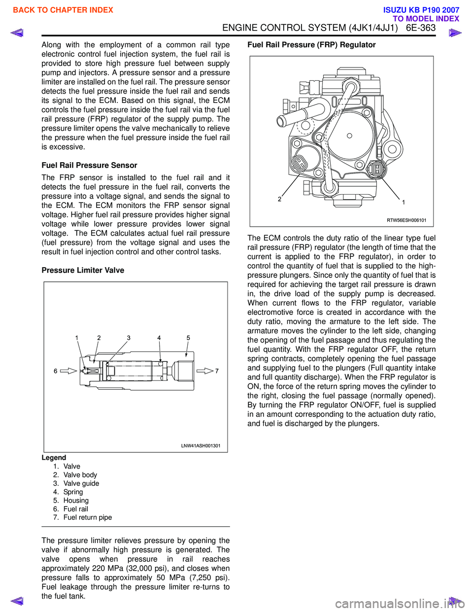
Pressure Limiter Valve
Legend 1. Valve
2. Valve body
3. Valve guide
4. Spring
5. Housing
6. Fuel rail
7. Fuel return pipe
The pressure limiter relieves pressure by opening the
valve if abnormally high pressure is generated. The
valve opens when pressure in rail reaches
approximately 220 MPa (32,000 psi), and closes when
pressure falls to approximately 50 MPa (7,250 psi).
Fuel leakage through the pressure limiter re-turns to
the fuel tank. Fuel Rail Pressure (FRP) Regulator
The ECM controls the duty ratio of the linear type fuel
rail pressure (FRP) regulator (the length of time that the
current is applied to the FRP regulator), in order to
control the quantity of fuel that is supplied to the high-
pressure plungers. Since only the quantity of fuel that is
required for achieving the target rail pressure is drawn
in, the drive load of the supply pump is decreased.
When current flows to the FRP regulator, variable
electromotive force is created in accordance with the
duty ratio, moving the armature to the left side. The
armature moves the cylinder to the left side, changing
the opening of the fuel passage and thus regulating the
fuel quantity. With the FRP regulator OFF, the return
spring contracts, completely opening the fuel passage
and supplying fuel to the plungers (Full quantity intake
and full quantity discharge). When the FRP regulator is
ON, the force of the return spring moves the cylinder to
the right, closing the fuel passage (normally opened).
By turning the FRP regulator ON/OFF, fuel is supplied
in an amount corresponding to the actuation duty ratio,
and fuel is discharged by the plungers.
LNW41ASH001301
12 3 4 5
7
6
RTW56ESH006101
12
BACK TO CHAPTER INDEX
TO MODEL INDEX
ISUZU KB P190 2007
Page 1981 of 6020
6E-364 ENGINE CONTROL SYSTEM (4JK1/4JJ1)
Fuel Injection System Description
Fuel Injection Quantity Control
This control determines the fuel injection quantity by
adding coolant temperature, fuel temperature, intake
air temperature, barometric pressure, mass air flow and
some switch inputs information corrections to the basic
injection quantity is calculated by the ECM based on
the engine operating conditions (engine speed,
accelerator pedal pressing amount and boost pressure
sensor). More fuel rate indicates if the engine load is
increased as the accelerator pedal is stepped on at
constant engine speed.
Combined with high pressure injection of atomized fuel,
this control improves exhaust gas and ensures proper
fuel consumption. Compared with conventional
mechanical governors, an electronic control system
provides higher degree of freedom of fuel injection
quantity control, thereby presenting high accelerator
response (acceleration feeling and pressing feeling).
Starting Injection Quantity Control
At the engine starting (after the key switch is turned to
the START position to start the engine, up to return of
key switch to the ON position), optimum fuel injection
quantity is controlled based on the information on the
engine speed and coolant temperature. At low
temperature, the fuel injection quantity increases.
When the engine started completely, this boosted
quantity mode at the starting is cancelled and normal
running mode is restored.
Idle Speed Control
A control is made so as to achieve stable idling speed
at all time regardless of engine secular changes or
engine condition variations. The ECM sets target idling
speed and controls the fuel injection quantity according
to the engine conditions (actual engine speed, coolant
temperature and engine load) to follow actual engine
speed to the target idling speed so as to ensure stable
idling speed.
Idle Vibration Control
A control is made so as to reduce the engine vibration
caused by torque variations between cylinders due to
variations in fuel injection quantity of each cylinder or
injector performance. The ECM corrects the injection
quantity between cylinders based on the revolution
signals from the crankshaft position (CKP) sensor.
Normal range of correction quantity between cylinders
is within ±5 mm
3.
BACK TO CHAPTER INDEX
TO MODEL INDEX
ISUZU KB P190 2007
Page 2122 of 6020
6C-4 ENGINE FUEL (C24SE)
Fuel Metering
Engine Control Module (ECM) is in complete control of this fuel
delivery system during normal driving conditions.
The intake manifold function, like that of a diesel, is used onl
y
to let air into the engine. The fuel is injected by separate
injectors that are mounted over the intake manifold.
The Manifold Absolute Pressure (MAP) sensor measures the
changes in the intake manifold pressure which result from
engine load and speed changes, which the MAP senso
r
converts to a voltage output.
This sensor generates the voltage to change corresponding to
the flow of the air drawn into the engine.
The changing voltage is transformed into an electric signal and
provided to the ECM.
W ith receipt of the signals sent from the MAP sensor, Intake
Air Temperature sensor and others, the ECM determines an
appropriate fuel injection pulse width feeding such information
to the fuel injector valves to effect an appropriate air/fuel ratio.
The Multiport Fuel Injection system utilizes an injection system
where the injectors turn on at every crankshaft revolution. The
ECM controls the injector on time so that the correct amount o
f
fuel is metered depending on driving conditions.
Two interchangeable "O" rings are used on the injector that
must be replaced when the injectors are removed.
The fuel rail is attached to the top of the intake manifold and
supplies fuel to all the injectors.
Fuel is recirculated through the rail continually while the engine
is running. This removes air and vapors from the fuel as well
as keeping the fuel cool during hot weather operation.
The fuel pressure control valve that is mounted on the fuel rail
maintains a pressure differential across the injectors under all
operating conditions. It is accomplished by controlling the
amount of fuel that is recirculated back to the fuel tank based
on engine demand.
See Section "Driveability and Emission" for more information
and diagnosis.
BACK TO CHAPTER INDEX
TO MODEL INDEX
ISUZU KB P190 2007