2007 ISUZU KB P190 turn signal
[x] Cancel search: turn signalPage 3259 of 6020
Engine Management – V6 – General Information Page 6C1-1–17
3.9 Serial Data Communication System
The engine control module (ECM) communicates directly with the following control units using the General Motors local
area network (GM LAN) serial data communication protocol:
• Transmission control module (TCM) (if fitted)
• Powertrain interface module (PIM)
The immobiliser control unit (ICU) communicates directly with the PIM using Keyword 2000 serial data communication
protocol. Refer to 11A Immobiliser for further information
As the GM LAN serial data communication protocol is not compatible with the Keyword 2000 serial data communication
protocol, a powertrain interface module (PIM) is integrated to the serial data communication system to perform the
following tasks (Refer to 6E1 Powertrain Interface Module – V6):
• Translate the GM LAN serial data transmitted by the ECM into a Keyword 2000 serial data that can be received
and recognised by the ICU.
• Translate the cruise control switch, automatic transmission power mode switch and 3
rd start switch signal into a GM
LAN serial data that can be received and recognised by the ECM.
3.10 Self Diagnostics System
The ECM constantly performs self-diagnostic tests on the engine management system. W hen the ECM detects a
malfunction, it also stores a diagnostic trouble code (DTC). A stored DTC will identify the problem area(s) and is
designed to assist the technician in rectifying the fault. In addition, DTCs are classified as either Current or History DTC.
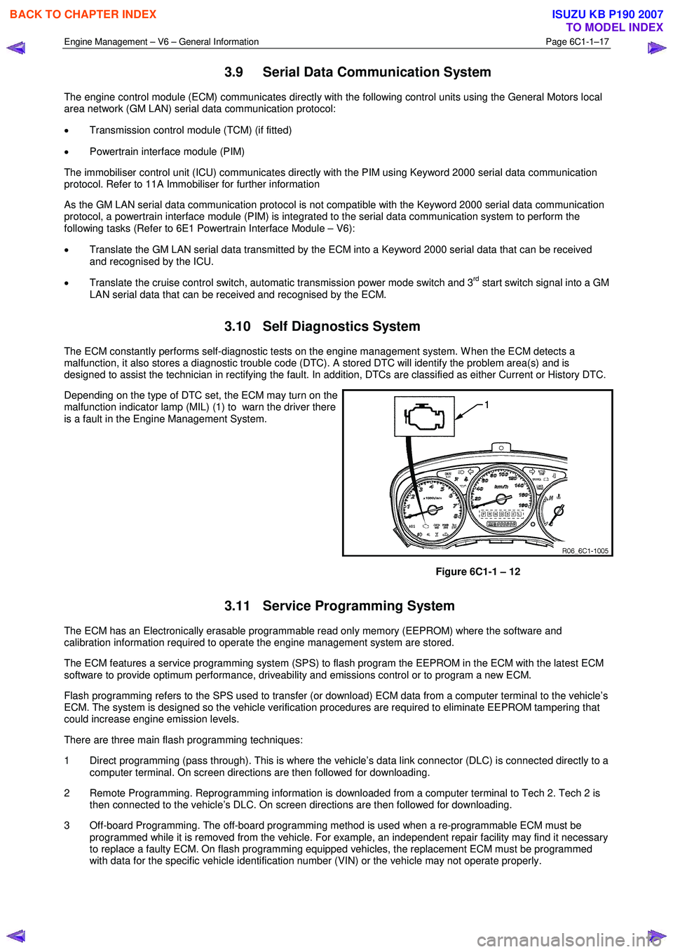
Depending on the type of DTC set, the ECM may turn on the
malfunction indicator lamp (MIL) (1) to warn the driver there
is a fault in the Engine Management System.
Figure 6C1-1 – 12
3.11 Service Programming System
The ECM has an Electronically erasable programmable read only memory (EEPROM) where the software and
calibration information required to operate the engine management system are stored.
The ECM features a service programming system (SPS) to flash program the EEPROM in the ECM with the latest ECM
software to provide optimum performance, driveability and emissions control or to program a new ECM.
Flash programming refers to the SPS used to transfer (or download) ECM data from a computer terminal to the vehicle’s
ECM. The system is designed so the vehicle verification procedures are required to eliminate EEPROM tampering that
could increase engine emission levels.
There are three main flash programming techniques:
1 Direct programming (pass through). This is where the vehicle’s data link connector (DLC) is connected directly to a computer terminal. On screen directions are then followed for downloading.
2 Remote Programming. Reprogramming information is downloaded from a computer terminal to Tech 2. Tech 2 is then connected to the vehicle’s DLC. On screen directions are then followed for downloading.
3 Off-board Programming. The off-board programming method is used when a re-programmable ECM must be programmed while it is removed from the vehicle. For example, an independent repair facility may find it necessary
to replace a faulty ECM. On flash programming equipped vehicles, the replacement ECM must be programmed
with data for the specific vehicle identification number (VIN) or the vehicle may not operate properly.
BACK TO CHAPTER INDEX
TO MODEL INDEX
ISUZU KB P190 2007
Page 3265 of 6020
Engine Management – V6 – General Information Page 6C1-1–23
4.8 Engine Coolant Temperature Sensor
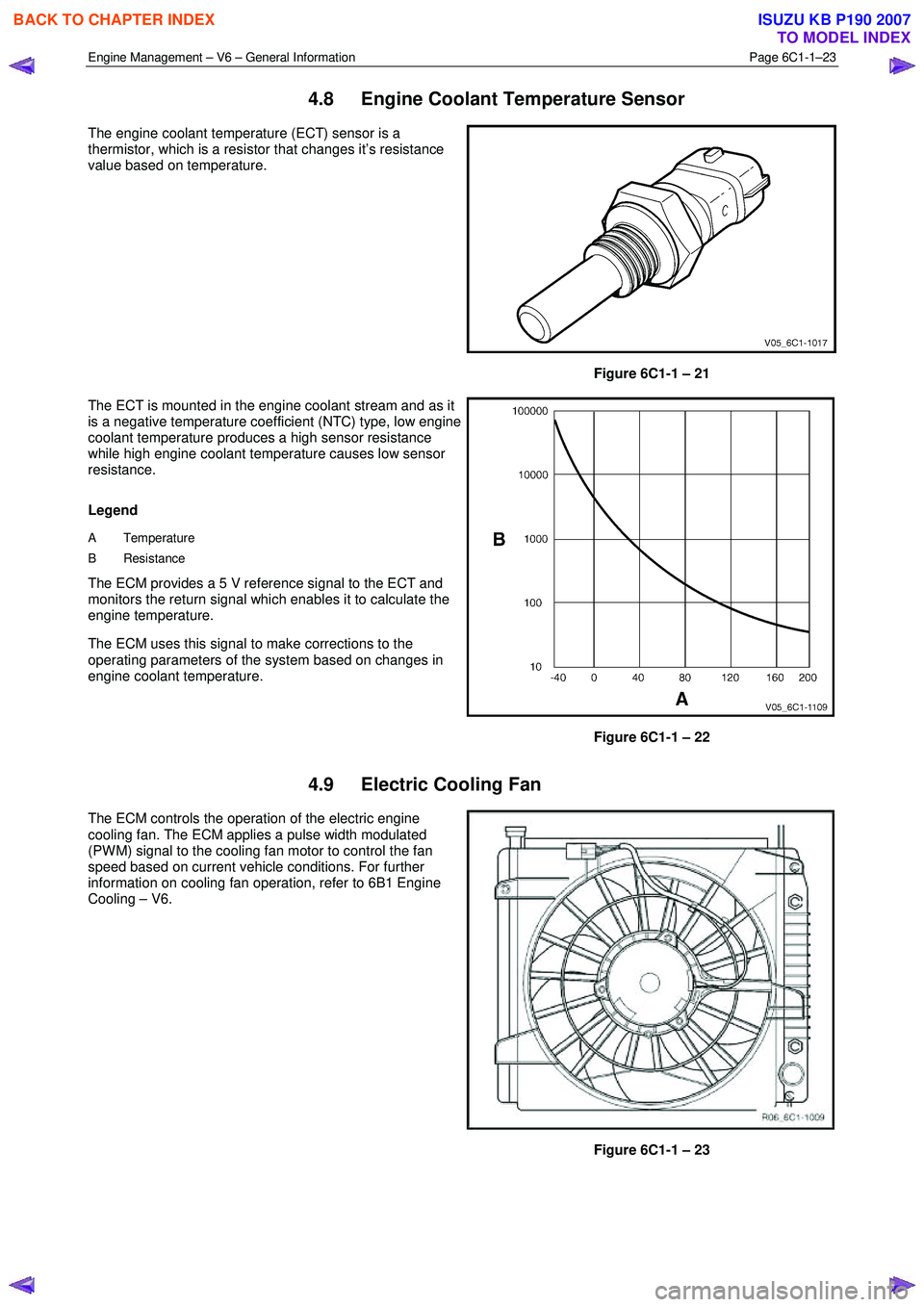
The engine coolant temperature (ECT) sensor is a
thermistor, which is a resistor that changes it’s resistance
value based on temperature.
Figure 6C1-1 – 21
The ECT is mounted in the engine coolant stream and as it
is a negative temperature coefficient (NTC) type, low engine
coolant temperature produces a high sensor resistance
while high engine coolant temperature causes low sensor
resistance.
Legend
A Temperature
B Resistance
The ECM provides a 5 V reference signal to the ECT and
monitors the return signal which enables it to calculate the
engine temperature.
The ECM uses this signal to make corrections to the
operating parameters of the system based on changes in
engine coolant temperature.
Figure 6C1-1 – 22
4.9 Electric Cooling Fan
The ECM controls the operation of the electric engine
cooling fan. The ECM applies a pulse width modulated
(PW M) signal to the cooling fan motor to control the fan
speed based on current vehicle conditions. For further
information on cooling fan operation, refer to 6B1 Engine
Cooling – V6.
Figure 6C1-1 – 23
BACK TO CHAPTER INDEX
TO MODEL INDEX
ISUZU KB P190 2007
Page 3266 of 6020
Engine Management – V6 – General Information Page 6C1-1–24
4.10 Engine Oil Level and Temperature
Sensor
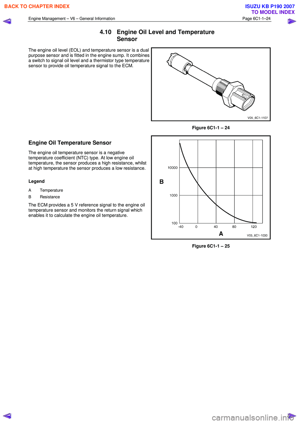
The engine oil level (EOL) and temperature sensor is a dual
purpose sensor and is fitted in the engine sump. It combines
a switch to signal oil level and a thermistor type temperature
sensor to provide oil temperature signal to the ECM.
Figure 6C1-1 – 24
Engine Oil Temperature Sensor
The engine oil temperature sensor is a negative
temperature coefficient (NTC) type. At low engine oil
temperature, the sensor produces a high resistance, whilst
at high temperature the sensor produces a low resistance.
Legend
A Temperature
B Resistance
The ECM provides a 5 V reference signal to the engine oil
temperature sensor and monitors the return signal which
enables it to calculate the engine oil temperature.
Figure 6C1-1 – 25
BACK TO CHAPTER INDEX
TO MODEL INDEX
ISUZU KB P190 2007
Page 3267 of 6020
Engine Management – V6 – General Information Page 6C1-1–25
Engine Oil Level Sensor
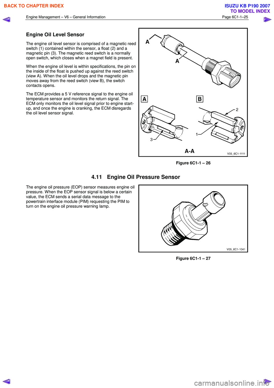
The engine oil level sensor is comprised of a magnetic reed
switch (1) contained within the sensor, a float (2) and a
magnetic pin (3). The magnetic reed switch is a normally
open switch, which closes when a magnet field is present.
W hen the engine oil level is within specifications, the pin on
the inside of the float is pushed up against the reed switch
(view A). W hen the oil level drops and the magnetic pin
moves away from the reed switch (view B), the switch
contacts opens.
The ECM provides a 5 V reference signal to the engine oil
temperature sensor and monitors the return signal. The
ECM only monitors the oil level signal prior to engine start-
up, and once the engine is cranking, the ECM disregards
the oil level sensor signal.
Figure 6C1-1 – 26
4.11 Engine Oil Pressure Sensor
The engine oil pressure (EOP) sensor measures engine oil
pressure. W hen the EOP sensor signal is below a certain
value, the ECM sends a serial data message to the
powertrain interface module (PIM) requesting the PIM to
turn on the engine oil pressure warning lamp.
Figure 6C1-1 – 27
BACK TO CHAPTER INDEX
TO MODEL INDEX
ISUZU KB P190 2007
Page 3274 of 6020
Engine Management – V6 – General Information Page 6C1-1–32
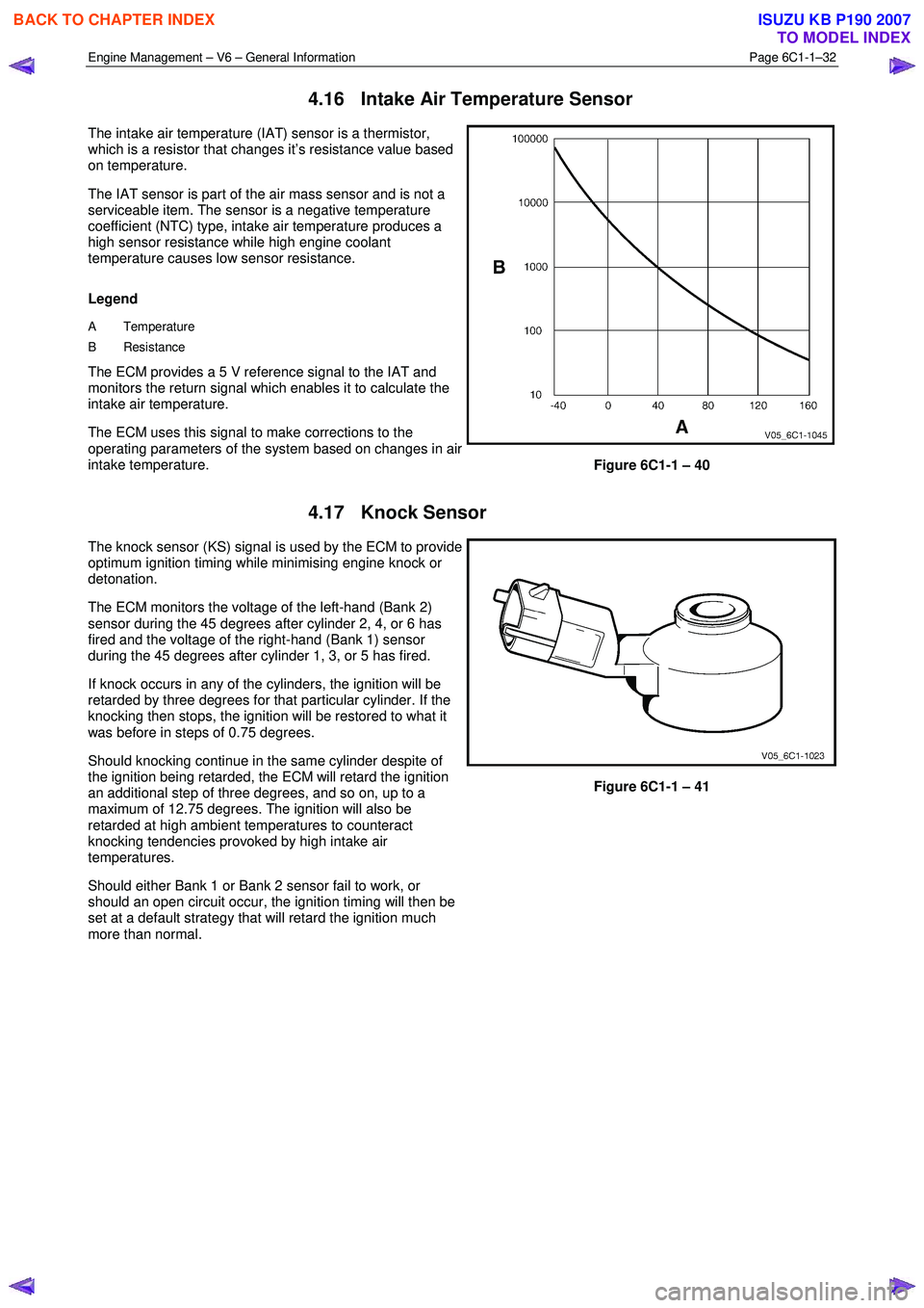
4.16 Intake Air Temperature Sensor
The intake air temperature (IAT) sensor is a thermistor,
which is a resistor that changes it’s resistance value based
on temperature.
The IAT sensor is part of the air mass sensor and is not a
serviceable item. The sensor is a negative temperature
coefficient (NTC) type, intake air temperature produces a
high sensor resistance while high engine coolant
temperature causes low sensor resistance.
Legend
A Temperature
B Resistance
The ECM provides a 5 V reference signal to the IAT and
monitors the return signal which enables it to calculate the
intake air temperature.
The ECM uses this signal to make corrections to the
operating parameters of the system based on changes in air
intake temperature.
Figure 6C1-1 – 40
4.17 Knock Sensor
The knock sensor (KS) signal is used by the ECM to provide
optimum ignition timing while minimising engine knock or
detonation.
The ECM monitors the voltage of the left-hand (Bank 2)
sensor during the 45 degrees after cylinder 2, 4, or 6 has
fired and the voltage of the right-hand (Bank 1) sensor
during the 45 degrees after cylinder 1, 3, or 5 has fired.
If knock occurs in any of the cylinders, the ignition will be
retarded by three degrees for that particular cylinder. If the
knocking then stops, the ignition will be restored to what it
was before in steps of 0.75 degrees.
Should knocking continue in the same cylinder despite of
the ignition being retarded, the ECM will retard the ignition
an additional step of three degrees, and so on, up to a
maximum of 12.75 degrees. The ignition will also be
retarded at high ambient temperatures to counteract
knocking tendencies provoked by high intake air
temperatures.
Should either Bank 1 or Bank 2 sensor fail to work, or
should an open circuit occur, the ignition timing will then be
set at a default strategy that will retard the ignition much
more than normal.
Figure 6C1-1 – 41
BACK TO CHAPTER INDEX
TO MODEL INDEX
ISUZU KB P190 2007
Page 3278 of 6020
Engine Management – V6 – General Information Page 6C1-1–36
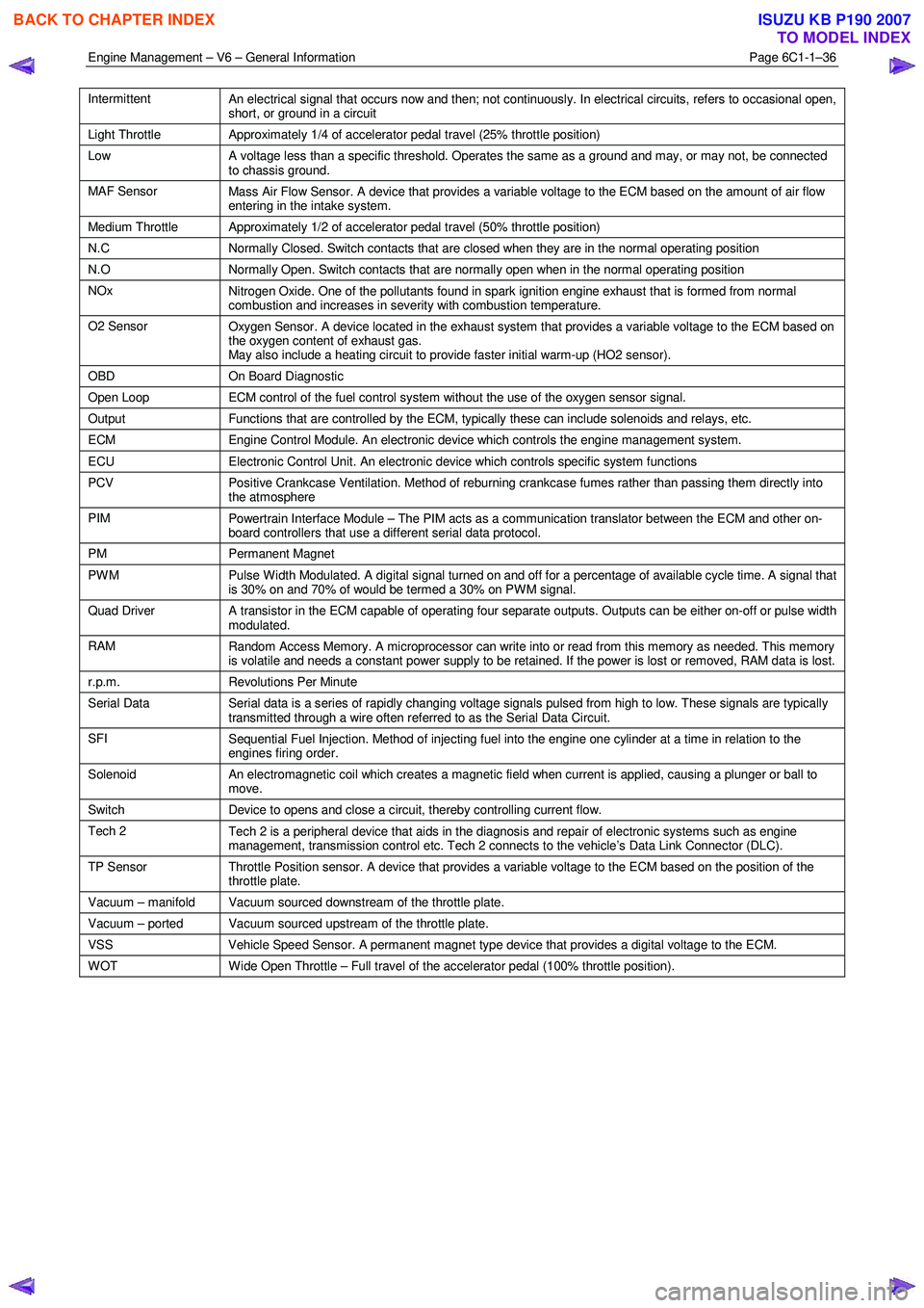
Intermittent
An electrical signal that occurs now and then; not continuously. In electrical circuits, refers to occasional open,
short, or ground in a circuit
Light Throttle Approximately 1/4 of accelerator pedal travel (25% throttle position)
Low
A voltage less than a specific threshold. Operates the same as a ground and may, or may not, be connected
to chassis ground.
MAF Sensor Mass Air Flow Sensor. A device that provides a variable voltage to the ECM based on the amount of air flow
entering in the intake system.
Medium Throttle Approximately 1/2 of accelerator pedal travel (50% throttle position)
N.C Normally Closed. Switch contacts that are closed when they are in the normal operating position
N.O Normally Open. Switch contacts that are normally open when in the normal operating position
NOx
Nitrogen Oxide. One of the pollutants found in spark ignition engine exhaust that is formed from normal
combustion and increases in severity with combustion temperature.
O2 Sensor Oxygen Sensor. A device located in the exhaust system that provides a variable voltage to the ECM based on
the oxygen content of exhaust gas.
May also include a heating circuit to provide faster initial warm-up (HO2 sensor).
OBD On Board Diagnostic
Open Loop ECM control of the fuel control system without the use of the oxygen sensor signal.
Output Functions that are controlled by the ECM, typically these can include solenoids and relays, etc.
ECM Engine Control Module. An electronic device which controls the engine management system.
ECU Electronic Control Unit. An electronic device which controls specific system functions
PCV
Positive Crankcase Ventilation. Method of reburning crankcase fumes rather than passing them directly into
the atmosphere
PIM Powertrain Interface Module – The PIM acts as a communication translator between the ECM and other on-
board controllers that use a different serial data protocol.
PM Permanent Magnet
PWM
Pulse Width Modulated. A digital signal turned on and off for a percentage of available cycle time. A signal that
is 30% on and 70% of would be termed a 30% on PWM signal.
Quad Driver A transistor in the ECM capable of operating four separate outputs. Outputs can be either on-off or pulse width
modulated.
RAM Random Access Memory. A microprocessor can write into or read from this memory as needed. This memory
is volatile and needs a constant power supply to be retained. If the power is lost or removed, RAM data is lost.
r.p.m. Revolutions Per Minute
Serial Data
Serial data is a series of rapidly changing voltage signals pulsed from high to low. These signals are typically
transmitted through a wire often referred to as the Serial Data Circuit.
SFI Sequential Fuel Injection. Method of injecting fuel into the engine one cylinder at a time in relation to the
engines firing order.
Solenoid An electromagnetic coil which creates a magnetic field when current is applied, causing a plunger or ball to
move.
Switch Device to opens and close a circuit, thereby controlling current flow.
Tech 2
Tech 2 is a peripheral device that aids in the diagnosis and repair of electronic systems such as engine
management, transmission control etc. Tech 2 connects to the vehicle’s Data Link Connector (DLC).
TP Sensor Throttle Position sensor. A device that provides a variable voltage to the ECM based on the position of the
throttle plate.
Vacuum – manifold Vacuum sourced downstream of the throttle plate.
Vacuum – ported Vacuum sourced upstream of the throttle plate.
VSS Vehicle Speed Sensor. A permanent magnet type device that provides a digital voltage to the ECM.
WOT Wide Open Throttle – Full travel of the accelerator pedal (100% throttle position).
BACK TO CHAPTER INDEX
TO MODEL INDEX
ISUZU KB P190 2007
Page 3291 of 6020
Engine Management – V6 – Diagnostics Page 6C1-2–13
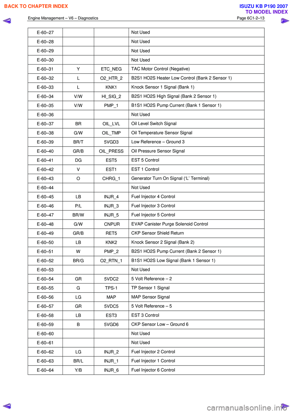
E-60–27 Not Used
E-60–28 Not Used
E-60–29 Not
Used
E-60–30 Not Used
E-60–31 Y ETC_NEG TAC Motor Control (Negative)
E-60–32 L O2_HTR_2 B2S1 HO2S Heater Low Control (Bank 2 Sensor 1)
E-60–33 L KNK1 Knock Sensor 1 Signal (Bank 1)
E-60–34 V/W HI_SIG_2 B2S1 HO2S High Signal (Bank 2 Sensor 1)
E-60–35 V/W PMP_1 B1S1 HO2S Pump Current (Bank 1 Sensor 1)
E-60–36 Not Used
E-60–37 BR OIL_LVL Oil Level Switch Signal
E-60–38 G/W OIL_TMP Oil Temperature Sensor Signal
E-60–39 BR/T 5VGD3 Low Reference – Ground 3
E-60–40 GR/B OIL_PRESS Oil Pressure Sensor Signal
E-60–41 DG EST5 EST 5 Control
E-60–42 V EST1 EST 1 Control
E-60–43 O CHRG_1 Generator Turn On Signal (‘L’ Terminal)
E-60–44 Not Used
E-60–45 LB INJR_4 Fuel Injector 4 Control
E-60–46 P/L INJR_3 Fuel Injector 3 Control
E-60–47 BR/W INJR_5 Fuel Injector 5 Control
E-60–48 G/W CNPUR EVAP Canister Purge Solenoid Control
E-60–49 GR/B RET5 CKP Sensor Shield Return
E-60–50 LB KNK2 Knock Sensor 2 Signal (Bank 2)
E-60–51 W PMP_2 B2S1 HO2S Pump Current (Bank 2 Sensor 1)
E-60–52 BR/G O2_RTN_1 B1S1 HO2S Low Signal (Bank 1 Sensor 1)
E-60–53 Not Used
E-60–54 GR 5VDC2 5 Volt Reference – 2
E-60–55 G TPS-1 TP Sensor 1 Signal
E-60–56 LG MAP MAP Sensor Signal
E-60–57 GR 5VDC5 5 Volt Reference – 5
E-60–58 LB EST3 EST 3 Control
E-60–59 B 5VGD6 CKP Sensor Low – Ground 6
E-60–60 Not Used
E-60–61 Not Used
E-60–62 LG INJR_2 Fuel Injector 2 Control
E-60–63 BR/L INJR_1 Fuel Injector 1 Control
E-60–64 Y/B INJR_6 Fuel Injector 6 Control
BACK TO CHAPTER INDEX
TO MODEL INDEX
ISUZU KB P190 2007
Page 3361 of 6020
Engine Management – V6 – Diagnostics Page 6C1-2–83
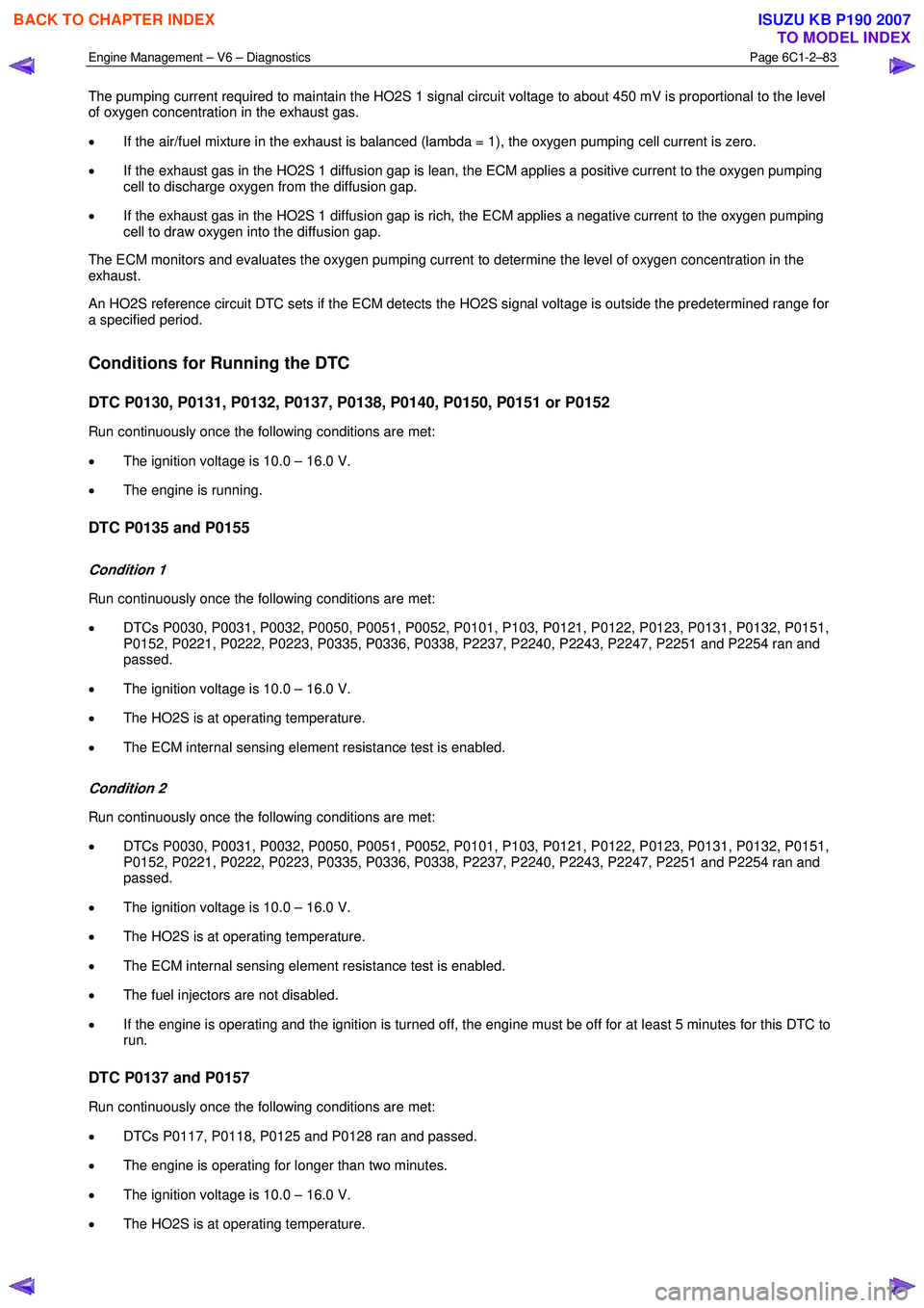
The pumping current required to maintain the HO2S 1 signal circuit voltage to about 450 mV is proportional to the level
of oxygen concentration in the exhaust gas.
• If the air/fuel mixture in the exhaust is balanced (lambda = 1), the oxygen pumping cell current is zero.
• If the exhaust gas in the HO2S 1 diffusion gap is lean, the ECM applies a positive current to the oxygen pumping
cell to discharge oxygen from the diffusion gap.
• If the exhaust gas in the HO2S 1 diffusion gap is rich, the ECM applies a negative current to the oxygen pumping
cell to draw oxygen into the diffusion gap.
The ECM monitors and evaluates the oxygen pumping current to determine the level of oxygen concentration in the
exhaust.
An HO2S reference circuit DTC sets if the ECM detects the HO2S signal voltage is outside the predetermined range for
a specified period.
Conditions for Running the DTC
DTC P0130, P0131, P0132, P0137, P0138, P0140, P0150, P0151 or P0152
Run continuously once the following conditions are met:
• The ignition voltage is 10.0 – 16.0 V.
• The engine is running.
DTC P0135 and P0155
Condition 1
Run continuously once the following conditions are met:
• DTCs P0030, P0031, P0032, P0050, P0051, P0052, P0101, P103, P0121, P0122, P0123, P0131, P0132, P0151,
P0152, P0221, P0222, P0223, P0335, P0336, P0338, P2237, P2240, P2243, P2247, P2251 and P2254 ran and
passed.
• The ignition voltage is 10.0 – 16.0 V.
• The HO2S is at operating temperature.
• The ECM internal sensing element resistance test is enabled.
Condition 2
Run continuously once the following conditions are met:
• DTCs P0030, P0031, P0032, P0050, P0051, P0052, P0101, P103, P0121, P0122, P0123, P0131, P0132, P0151,
P0152, P0221, P0222, P0223, P0335, P0336, P0338, P2237, P2240, P2243, P2247, P2251 and P2254 ran and
passed.
• The ignition voltage is 10.0 – 16.0 V.
• The HO2S is at operating temperature.
• The ECM internal sensing element resistance test is enabled.
• The fuel injectors are not disabled.
• If the engine is operating and the ignition is turned off, the engine must be off for at least 5 minutes for this DTC to
run.
DTC P0137 and P0157
Run continuously once the following conditions are met:
• DTCs P0117, P0118, P0125 and P0128 ran and passed.
• The engine is operating for longer than two minutes.
• The ignition voltage is 10.0 – 16.0 V.
• The HO2S is at operating temperature.
BACK TO CHAPTER INDEX
TO MODEL INDEX
ISUZU KB P190 2007