2007 ISUZU KB P190 indicator
[x] Cancel search: indicatorPage 3982 of 6020
7A2-16 TRANSMISSION CONTROL SYSTEM (AW30–40LE)
CAN bus systems in automatic
transmission control (AW30-40LE)
The automatic transmission control system in AW 30-
40LE uses high speed CAN bus system .The individual
CAN bus systems are connected via two interfaces and
can exchange information and data. This allows control
modules that are connected to different CAN bus
systems to communicate.
High speed CAN bus
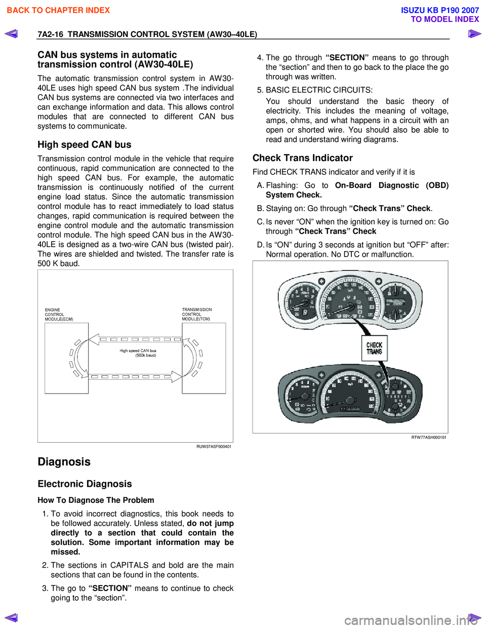
Transmission control module in the vehicle that require
continuous, rapid communication are connected to the
high speed CAN bus. For example, the automatic
transmission is continuously notified of the current
engine load status. Since the automatic transmission
control module has to react immediately to load status
changes, rapid communication is required between the
engine control module and the automatic transmission
control module. The high speed CAN bus in the AW 30-
40LE is designed as a two-wire CAN bus (twisted pair).
The wires are shielded and twisted. The transfer rate is
500 K baud.
RUW 37ASF000401
Diagnosis
Electronic Diagnosis
How To Diagnose The Problem
1. To avoid incorrect diagnostics, this book needs to
be followed accurately. Unless stated, do not jump
directly to a section that could contain the
solution. Some important information may be
missed.
2. The sections in CAPITALS and bold are the main
sections that can be found in the contents.
3. The go to “SECTION” means to continue to check
going to the “section”.
4. The go through “SECTION” means to go through
the “section” and then to go back to the place the go
through was written.
5. BASIC ELECTRIC CIRCUITS:
You should understand the basic theory o
f
electricity. This includes the meaning of voltage,
amps, ohms, and what happens in a circuit with an
open or shorted wire. You should also be able to
read and understand wiring diagrams.
Check Trans Indicator
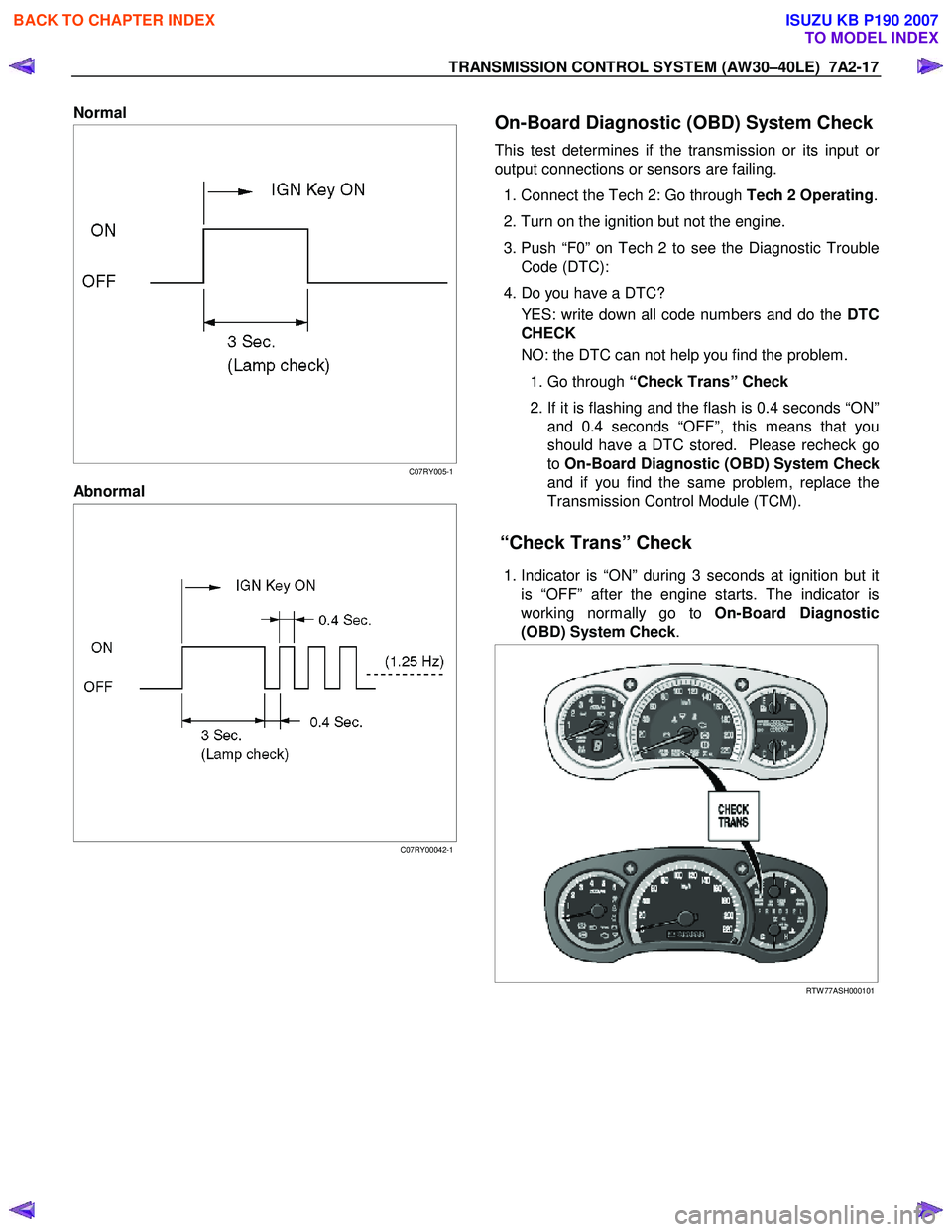
Find CHECK TRANS indicator and verify if it is
A. Flashing: Go to On-Board Diagnostic (OBD)
System Check.
B. Staying on: Go through “Check Trans” Check.
C. Is never “ON” when the ignition key is turned on: Go through “Check Trans” Check
D. Is “ON” during 3 seconds at ignition but “OFF” after: Normal operation. No DTC or malfunction.
RTW 77ASH000101
BACK TO CHAPTER INDEX
TO MODEL INDEX
ISUZU KB P190 2007
Page 3983 of 6020
TRANSMISSION CONTROL SYSTEM (AW30–40LE) 7A2-17
Normal
C07RY005-1
Abnormal
C07RY00042-1
On-Board Diagnostic (OBD) System Check
This test determines if the transmission or its input or
output connections or sensors are failing.
1. Connect the Tech 2: Go through Tech 2 Operating.
2. Turn on the ignition but not the engine.
3. Push “F0” on Tech 2 to see the Diagnostic Trouble Code (DTC):
4. Do you have a DTC? YES: write down all code numbers and do the DTC
CHECK
NO: the DTC can not help you find the problem.
1. Go through “Check Trans” Check
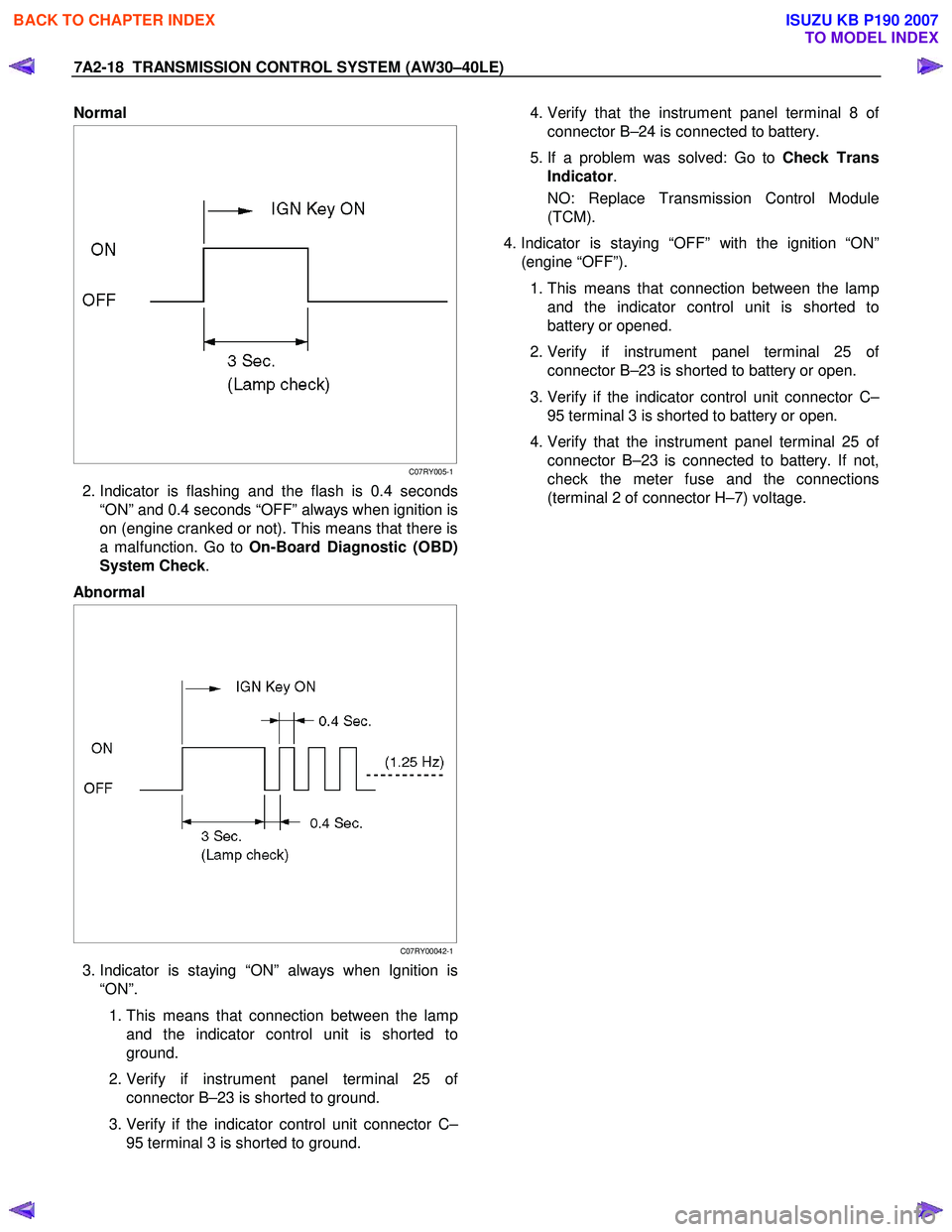
2. If it is flashing and the flash is 0.4 seconds “ON”
and 0.4 seconds “OFF”, this means that you
should have a DTC stored. Please recheck go
to On-Board Diagnostic (OBD) System Chec
k
and if you find the same problem, replace the
Transmission Control Module (TCM).
“Check Trans” Check
1. Indicator is “ON” during 3 seconds at ignition but it
is “OFF” after the engine starts. The indicator is
working normally go to On-Board Diagnostic
(OBD) System Check .
RTW 77ASH000101
BACK TO CHAPTER INDEX
TO MODEL INDEX
ISUZU KB P190 2007
Page 3984 of 6020
7A2-18 TRANSMISSION CONTROL SYSTEM (AW30–40LE)
Normal
C07RY005-1
2. Indicator is flashing and the flash is 0.4 seconds
“ON” and 0.4 seconds “OFF” always when ignition is
on (engine cranked or not). This means that there is
a malfunction. Go to On-Board Diagnostic (OBD)
System Check .
Abnormal
C07RY00042-1
3. Indicator is staying “ON” always when Ignition is
“ON”.
1. This means that connection between the lamp
and the indicator control unit is shorted to
ground.
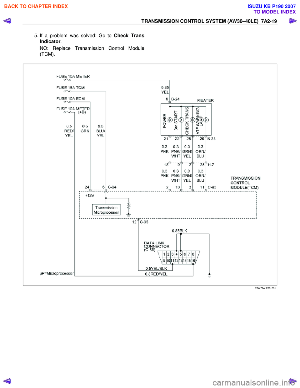
2. Verify if instrument panel terminal 25 o
f
connector B–23 is shorted to ground.
3. Verify if the indicator control unit connector C–
95 terminal 3 is shorted to ground.
4. Verify that the instrument panel terminal 8 o
f
connector B–24 is connected to battery.
5. If a problem was solved: Go to Check Trans
Indicator .
NO: Replace Transmission Control Module
(TCM).
4. Indicator is staying “OFF” with the ignition “ON”
(engine “OFF”).
1. This means that connection between the lamp
and the indicator control unit is shorted to
battery or opened.
2. Verify if instrument panel terminal 25 o
f
connector B–23 is shorted to battery or open.
3. Verify if the indicator control unit connector C–
95 terminal 3 is shorted to battery or open.
4. Verify that the instrument panel terminal 25 o
f
connector B–23 is connected to battery. If not,
check the meter fuse and the connections
(terminal 2 of connector H–7) voltage.
BACK TO CHAPTER INDEX
TO MODEL INDEX
ISUZU KB P190 2007
Page 3985 of 6020
TRANSMISSION CONTROL SYSTEM (AW30–40LE) 7A2-19
5. If a problem was solved: Go to Check Trans
Indicator .
NO: Replace Transmission Control Module
(TCM).
RTW 77ALF001301
BACK TO CHAPTER INDEX
TO MODEL INDEX
ISUZU KB P190 2007
Page 4005 of 6020
TRANSMISSION CONTROL SYSTEM (AW30–40LE) 7A2-39
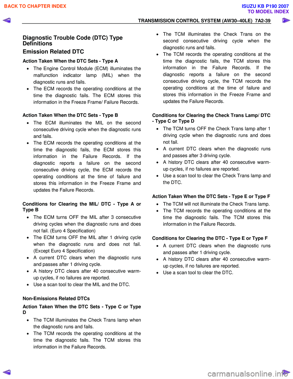
Diagnostic Trouble Code (DTC) Type
Definitions
Emission Related DTC
Action Taken When the DTC Sets - Type A
• The Engine Control Module (ECM) illuminates the
malfunction indicator lamp (MIL) when the
diagnostic runs and fails.
• The ECM records the operating conditions at the
time the diagnostic fails. The ECM stores this
information in the Freeze Frame/ Failure Records.
Action Taken When the DTC Sets - Type B
• The ECM illuminates the MIL on the second
consecutive driving cycle when the diagnostic runs
and fails.
• The ECM records the operating conditions at the
time the diagnostic fails, the ECM stores this
information in the Failure Records. If the
diagnostic reports a failure on the second
consecutive driving cycle, the ECM records the
operating conditions at the time of failure and
stores this information in the Freeze Frame and
updates the Failure Records.
Conditions for Clearing the MIL/ DTC - Type A o
r
Type B • The ECM turns OFF the MIL after 3 consecutive
driving cycles when the diagnostic runs and does
not fail. (Euro 4 Specification)
• The ECM turns OFF the MIL after 1 driving cycle
when the diagnostic runs and does not fail.
(Except Euro 4 Specification)
•
A current DTC clears when the diagnostic runs
and passes after 1 driving cycle.
• A history DTC clears after 40 consecutive warm-
up cycles, if no failures are reported.
• Use a scan tool to clear the MIL and the DTC.
Non-Emissions Related DTCs
Action Taken When the DTC Sets - Type C or Type
D
• The TCM illuminates the Check Trans lamp when
the diagnostic runs and fails.
• The TCM records the operating conditions at the
time the diagnostic fails. The TCM stores this
information in the Failure Records.
• The TCM illuminates the Check Trans on the
second consecutive driving cycle when the
diagnostic runs and fails.
• The TCM records the operating conditions at the
time the diagnostic fails, the TCM stores this
information in the Failure Records. If the
diagnostic reports a failure on the second
consecutive driving cycle, the TCM records the
operating conditions at the time of failure and
stores this information in the Freeze Frame and
updates the Failure Records.
Conditions for Clearing the Check Trans Lamp/ DTC
- Type C or Type D
• The TCM turns OFF the Check Trans lamp after 1
driving cycle when the diagnostic runs and does
not fail.
•
A current DTC clears when the diagnostic runs
and passes after 3 driving cycle.
• A history DTC clears after 40 consecutive warm-
up cycles, if no failures are reported.
• Use a scan tool to clear the Check Trans lamp and
the DTC.
Action Taken When the DTC Sets - Type E or Type F • The TCM will not illuminate the Check Trans lamp.
• The TCM records the operating conditions at the
time the diagnostic fails. The TCM stores this
information in the Failure Records.
Conditions for Clearing the DTC - Type E or Type F •
A current DTC clears when the diagnostic runs
and passes after 1 driving cycle.
• A history DTC clears after 40 consecutive warm-
up cycles, if no failures are reported.
• Use a scan tool to clear the DTC.
BACK TO CHAPTER INDEX
TO MODEL INDEX
ISUZU KB P190 2007
Page 4110 of 6020
ON-VEHICLE SERVICE (AW30–40LE) 7A3-25
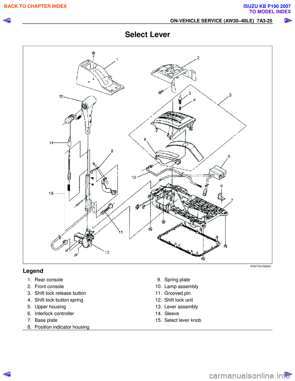
Select Lever
RTW 77ALF000201
Legend
1. Rear console
2. Front console
3. Shift lock release button
4. Shift lock button spring 5. Upper housing
6. Interlock controller
7. Base plate
8. Position indicator housing
9. Spring plate
10. Lamp assembly
11. Grooved pin
12. Shift lock unit
13. Lever assembly
14. Sleeve
15. Select lever knob
BACK TO CHAPTER INDEX
TO MODEL INDEX
ISUZU KB P190 2007
Page 4111 of 6020
7A3-26 ON-VEHICLE SERVICE (AW30–40LE)
Remove or Disconnect
1. Block the wheels.
2. Disconnect the negative battery cable.
3. Remove the rear console and the front console.
4. Remove the 2 screws fixing the select lever knob.
5. Remove the knob together with the knob button and spring from the lever.
6. Turn the sleeve counterclockwise to remove it. Make a note of the number of turns required to free
the sleeve.
7. Remove the harness connectors from the base plate.
8. Remove the upper housing (held in place by 4 latched fasteners).
9. Remove the lamp assembly by turning it counterclockwise.
10. Remove the spring plate.
11. Remove the grooved pin.
12. Disconnect the shift cable from the select lever.
13. Remove the lever assembly by pressing the rod down (lever in N position).
14. Remove the harness connectors from the shift lock unit, then remove the shift lock unit.
15. Remove the interlock controller.
16. If the replacement of shift lock release button o
r
shift lock button spring is required, remove the
position indicator housing, the shift lock button
spring and shift lock release button can be
removed.
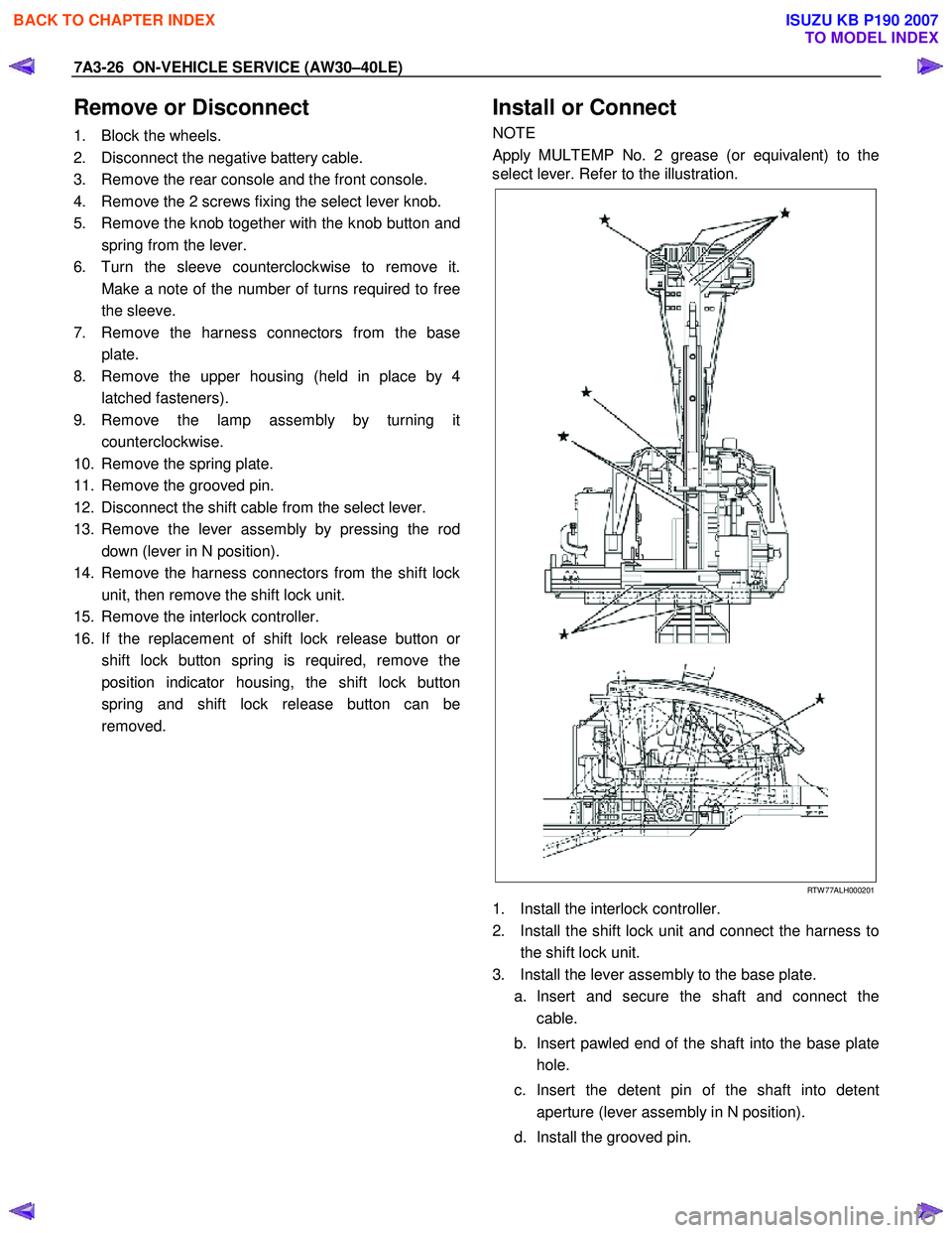
Install or Connect
NOTE
Apply MULTEMP No. 2 grease (or equivalent) to the
select lever. Refer to the illustration.
RTW 77ALH000201
1. Install the interlock controller.
2. Install the shift lock unit and connect the harness to the shift lock unit.
3. Install the lever assembly to the base plate. a. Insert and secure the shaft and connect the cable.
b. Insert pawled end of the shaft into the base plate hole.
c. Insert the detent pin of the shaft into detent aperture (lever assembly in N position).
d. Install the grooved pin.
BACK TO CHAPTER INDEX
TO MODEL INDEX
ISUZU KB P190 2007
Page 4152 of 6020
UNIT REPAIR (AW30–40LE) 7A4–17
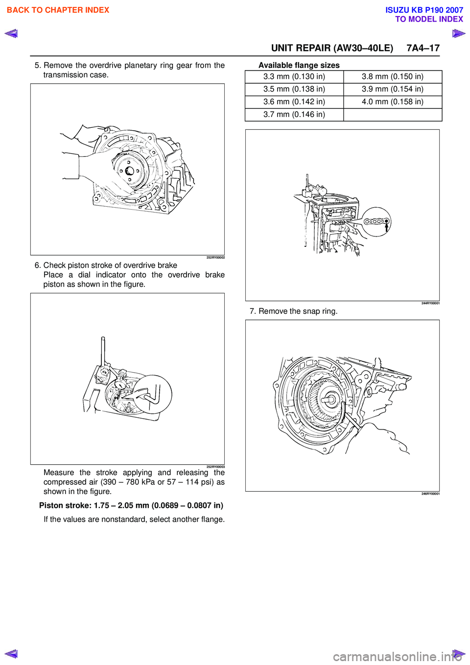
5. Remove the overdrive planetary ring gear from thetransmission case.
252RY00002
6. Check piston stroke of overdrive brakePlace a dial indicator onto the overdrive brake
piston as shown in the figure.
252RY00003Measure the stroke applying and releasing the
compressed air (390 – 780 kPa or 57 – 114 psi) as
shown in the figure.
Piston stroke: 1.75 – 2.05 mm (0.0689 – 0.0807 in)
If the values are nonstandard, select another flange. Available flange sizes
244RY00001
7. Remove the snap ring.
246RY00001
3.3 mm (0.130 in) 3.8 mm (0.150 in)
3.5 mm (0.138 in) 3.9 mm (0.154 in)
3.6 mm (0.142 in) 4.0 mm (0.158 in)
3.7 mm (0.146 in)
BACK TO CHAPTER INDEX
TO MODEL INDEX
ISUZU KB P190 2007