2007 ISUZU KB P190 indicator
[x] Cancel search: indicatorPage 3598 of 6020
Charging System – V6 Page 6D1-1-11
3.3 On-vehicle Testing
Generator On-vehicle Checks
Prerequisites
Before testing the generator output, ensure that:
• all generator circuit connections are clean and tight,
• the generator is always connected to the battery during testing (to prevent damage to the diodes),
• the battery is fully charged, and
• the specific gravity does not vary more than 0.025 between cells. (It is recommended the average specific gravity
is 1.260 or higher). Refer to 6D1-3 Battery – V6.
Carry out a load test on the battery to determine its ability to supply and accept current. This is a good indicator of the
general condition of the battery. For details of battery testing, refer to 6D1-3 Battery – V6.
Inspect the drive belt and tensioner markings to determine if the drive belt is within operating limits. Replace the belt if it
is excessively worn or outside the operating range of the tensioner.
For further details, refer to 6A1 Engine Mechanical – V6.
Generator Test
Regulating Voltage Test
NOTE
Leave the generator E-4 wiring harness
connector connected, as it provides initial field
excitation.
1 Ensure the ignition switch is in the OFF position and all electrical equipment is turned off.
Refer to 1.2 WARNING, CAUTION and
NOTES before disconnecting the battery.
2 Disconnect the battery ground cable P-5 at the battery.
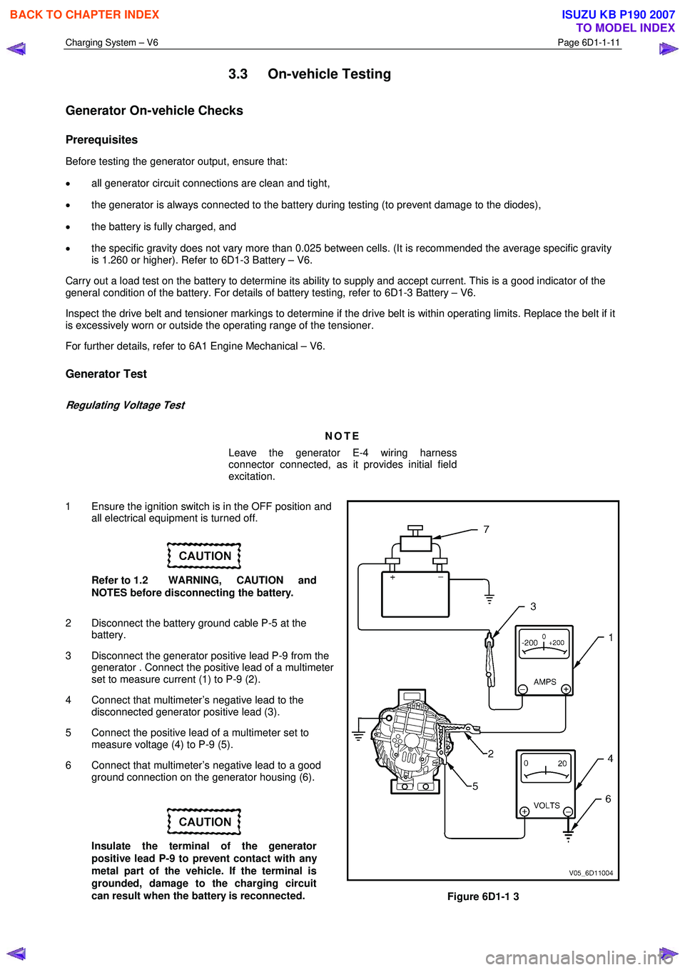
3 Disconnect the generator positive lead P-9 from the generator . Connect the positive lead of a multimeter
set to measure current (1) to P-9 (2).
4 Connect that multimeter’s negative lead to the disconnected generator positive lead (3).
5 Connect the positive lead of a multimeter set to measure voltage (4) to P-9 (5).
6 Connect that multimeter’s negative lead to a good ground connection on the generator housing (6).
Insulate the terminal of the generator
positive lead P-9 to prevent contact with any
metal part of the vehicle. If the terminal is
grounded, damage to the charging circuit
can result when the battery is reconnected.
Figure 6D1-1 3
BACK TO CHAPTER INDEX
TO MODEL INDEX
ISUZU KB P190 2007
Page 3600 of 6020
Charging System – V6 Page 6D1-1-13
20 Reduce the engine speed to idle.
On completion of the generator output test,
return the engine to idle and disconnect the
loading device from the battery terminals.
This prevents excessive battery discharge.
21 Stop the engine.
22 Disconnect the battery ground cable P-5 at the battery.
23 Remove the multimeters.
24 Reconnect the generator positive lead P-9.
25 Reconnect the battery ground cable P-5 to the battery.
Engine RPM............................................................ 1900
Load ................................................................ 5.0 – 10 A
Output Voltage ........................................... 13.8 – 15.4 V
Charging Circuit Voltage Drop Test
Prerequisites
Before testing the generator output, ensure that:
• all generator circuit connections are clean and tight,
• the generator is always connected to the battery during testing (to prevent damage to the diodes),
• the battery is fully charged, and
• the specific gravity does not vary more than 0.025 between cells. (It is recommended the average specific gravity
is 1.260 or higher). Refer to 6D1-3 Battery – V6.
Carry out a load test on the battery to determine its ability to supply and accept current. This is a good indicator of the
general condition of the battery. For details of battery testing, refer to 6D1-3 Battery – V6.
Inspect the drive belt and tensioner markings to determine if the drive belt is within operating limits. Replace the belt if it
is excessively worn or outside the operating range of the tensioner.
For further details, refer to 6A1 Engine Mechanical – V6.
Voltage Drop Test
Ensure the generator connections are clean
and tight.
1 Connect the positive lead of a multimeter set to measure voltage to the generator terminal P-9.
2 Connect the negative lead of the multimeter to the battery positive post.
3 Switch the headlamps on.
4 Start the engine.
5 Increase the engine speed to approximately 2500 r.p.m.
6 Record the voltage reading.
7 Reduce the engine speed to idle.
BACK TO CHAPTER INDEX
TO MODEL INDEX
ISUZU KB P190 2007
Page 3603 of 6020
Charging System – V6 Page 6D1-1-16
Reinstall
Reinstallation of the generator is the reverse of the removal procedure, noting the following:
1 Tighten all fasteners to the correct torque specification.
2 Reconnect the battery ground lead.
3 Start the engine.
4 Check the generator warning indicator operation.
5 Check the drive belt is correctly routed and aligned.
6 Check the generator output. Refer to 3.3 On-vehicle Testing.
7 Check the voltage regulator operation. Refer to 3.3 On-vehicle Testing.
8 Turn the ignition switch off.
Generator mounting bolts ........................... (1) 58.0 Nm
Generator mounting bolts ........................... (2) 58.0 Nm
Generator mounting bolts ........................... (4) 58.0 Nm
Battery harness to P-9 pin B nut
torque specification ...................................7.1 – 13.3 Nm
BACK TO CHAPTER INDEX
TO MODEL INDEX
ISUZU KB P190 2007
Page 3628 of 6020
Starting System – V6 Page 6D1-2–20
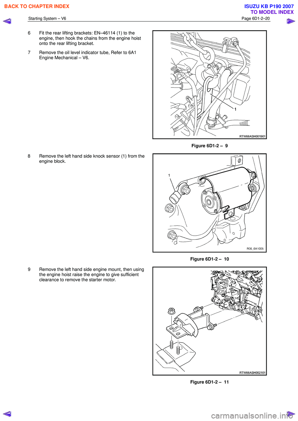
6 Fit the rear lifting brackets: EN–46114 (1) to the
engine, then hook the chains from the engine hoist
onto the rear lifting bracket.
7 Remove the oil level indicator tube, Refer to 6A1 Engine Mechanical – V6.
Figure 6D1-2 – 9
8 Remove the left hand side knock sensor (1) from the engine block.
Figure 6D1-2 – 10
9 Remove the left hand side engine mount, then using the engine hoist raise the engine to give sufficient
clearance to remove the starter motor.
Figure 6D1-2 – 11
BACK TO CHAPTER INDEX
TO MODEL INDEX
ISUZU KB P190 2007
Page 3632 of 6020
Starting System – V6 Page 6D1-2–24
No Load Test
1 Clamp the starter motor securely to a test bench.
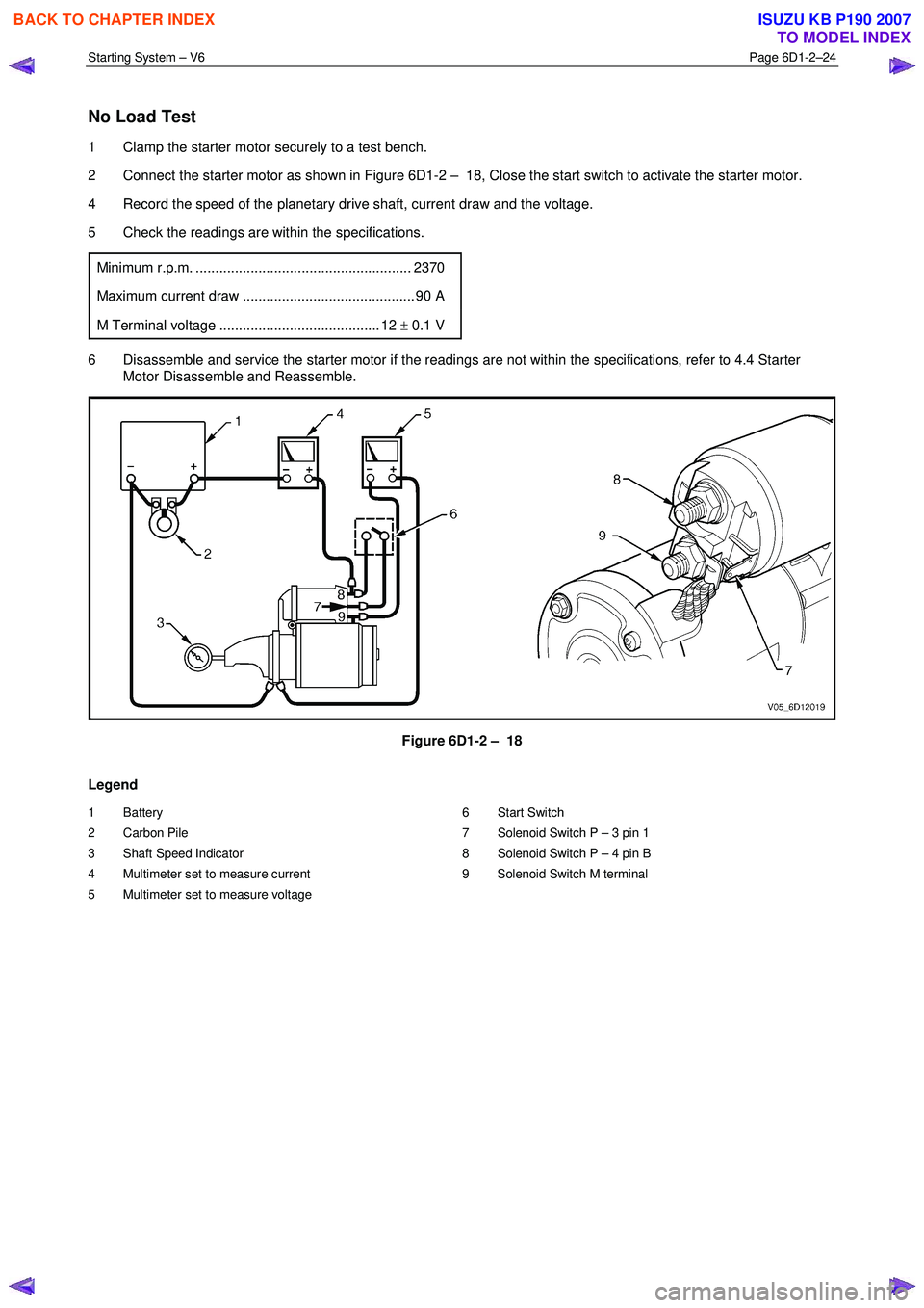
2 Connect the starter motor as shown in Figure 6D1-2 – 18, Close the start switch to activate the starter motor.
4 Record the speed of the planetary drive shaft, current draw and the voltage.
5 Check the readings are within the specifications.
Minimum r.p.m. ....................................................... 2370
Maximum current draw ............................................ 90 A
M Terminal voltage ......................................... 12 ± 0.1 V
6 Disassemble and service the starter motor if the readings are not within the specifications, refer to 4.4 Starter
Motor Disassemble and Reassemble.
Figure 6D1-2 – 18
Legend
1 Battery
2 Carbon Pile
3 Shaft Speed Indicator
4 Multimeter set to measure current
5 Multimeter set to measure voltage 6 Start Switch
7 Solenoid Switch P – 3 pin 1
8 Solenoid Switch P – 4 pin B
9 Solenoid Switch M terminal
BACK TO CHAPTER INDEX
TO MODEL INDEX
ISUZU KB P190 2007
Page 3665 of 6020
Powertrain Interface Module – V6 Page 6E1–4
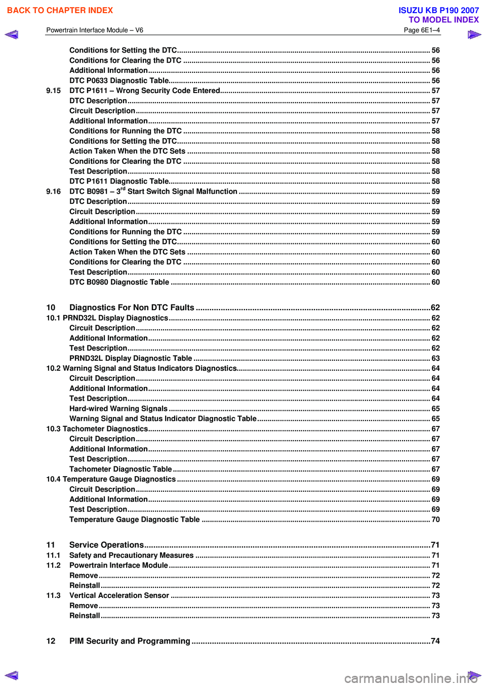
Conditions for Setting the DTC........................................................................................................................... 56
Conditions for Clearing the DTC ................................................................................................ ........................ 56
Additional Information......................................................................................................................................... 56
DTC P0633 Diagnostic Table..................................................................................................... .......................... 56
9.15 DTC P1611 – Wrong Security Code Entered........................................................................................ .............. 57
DTC Description ................................................................................................................................................... 57
Circuit Description ............................................................................................................................................... 57
Additional Information......................................................................................................... ................................ 57
Conditions for Running the DTC ................................................................................................. ....................... 58
Conditions for Setting the DTC........................................................................................................................... 58
Action Taken When the DTC Sets ................................................................................................. ..................... 58
Conditions for Clearing the DTC ........................................................................................................................ 58
Test Description ................................................................................................................................................... 58
DTC P1611 Diagnostic Table..................................................................................................... .......................... 58
9.16 DTC B0981 – 3rd Start Switch Signal Malfunction ............................................................................................. 59
DTC Description ................................................................................................................................................... 59
Circuit Description ............................................................................................................................................... 59
Additional Information......................................................................................................... ................................ 59
Conditions for Running the DTC ................................................................................................. ....................... 59
Conditions for Setting the DTC........................................................................................................................... 60
Action Taken When the DTC Sets ................................................................................................. ..................... 60
Conditions for Clearing the DTC ........................................................................................................................ 60
Test Description ................................................................................................................................................... 60
DTC B0980 Diagnostic Table ..................................................................................................... ......................... 60
10 Diagnostics For Non DTC Faults ................................................................................................. .......62
10.1 PRND32L Display Diagnostics ............................................................................................... ................................ 62
Circuit Description ............................................................................................................................................... 62
Additional Information......................................................................................................... ................................ 62
Test Description ................................................................................................................................................... 62
PRND32L Display Diagnostic Table ............................................................................................... .................... 63
10.2 Warning Signal and Status Indicators Diagnostics.......................................................................... .................... 64
Circuit Description ............................................................................................................................................... 64
Additional Information......................................................................................................... ................................ 64
Test Description ................................................................................................................................................... 64
Hard-wired Warning Signals ..................................................................................................... .......................... 65
Warning Signal and Status Indicator Diagnostic Table ........................................................................... ......... 65
10.3 Tachometer Diagnostics......................................................................................................................................... 67
Circuit Description ............................................................................................................................................... 67
Additional Information......................................................................................................... ................................ 67
Test Description ................................................................................................................................................... 67
Tachometer Diagnostic Table .................................................................................................... ......................... 67
10.4 Temperature Gauge Diagnostics ............................................................................................. .............................. 69
Circuit Description ............................................................................................................................................... 69
Additional Information......................................................................................................... ................................ 69
Test Description ................................................................................................................................................... 69
Temperature Gauge Diagnostic Table ............................................................................................. .................. 70
11 Service Operations ...............................................................................................................................71
11.1 Safety and Precautionary Measures .................................................................................................................. 71
11.2 Powertrain Interface Module ............................................................................................................................... 71
Remove ................................................................................................................................................................. 72
Reinstall ................................................................................................................................................................ 72
11.3 Vertical Acceleration Sensor ................................................................................................... ........................... 73
Remove ................................................................................................................................................................. 73
Reinstall ................................................................................................................................................................ 73
12 PIM Security and Programming ................................................................................................... .......74
BACK TO CHAPTER INDEX
TO MODEL INDEX
ISUZU KB P190 2007
Page 3666 of 6020
Powertrain Interface Module – V6 Page 6E1–5
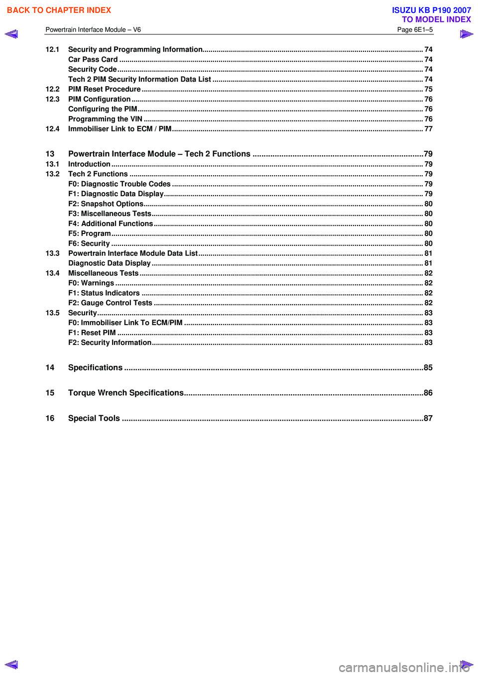
12.1 Security and Programming Information............................................................................................................. 74
Car Pass Card ...................................................................................................................................................... 74
Security Code ....................................................................................................................................................... 74
Tech 2 PIM Security Information Data List ...................................................................................... .................. 74
12.2 PIM Reset Procedure ........................................................................................................................................... 75
12.3 PIM Configuration ................................................................................................................................................ 76
Configuring the PIM ............................................................................................................ ................................. 76
Programming the VIN ............................................................................................................ .............................. 76
12.4 Immobiliser Link to ECM / PIM .................................................................................................. .......................... 77
13 Powertrain Interface Module – Tech 2 Functions .............................................................................79
13.1 Introduction .......................................................................................................................................................... 79
13.2 Tech 2 Functions ............................................................................................................... .................................. 79
F0: Diagnostic Trouble Codes ................................................................................................... ......................... 79
F1: Diagnostic Data Display................................................................................................................................ 79
F2: Snapshot Options.......................................................................................................................................... 80
F3: Miscellaneous Tests........................................................................................................ .............................. 80
F4: Additional Functions ..................................................................................................................................... 80
F5: Program .......................................................................................................................................................... 80
F6: Security .......................................................................................................................................................... 80
13.3 Powertrain Interface Module Data List .......................................................................................... ..................... 81
Diagnostic Data Display ...................................................................................................................................... 81
13.4 Miscellaneous Tests ............................................................................................................................................ 82
F0: Warnings ........................................................................................................................................................ 82
F1: Status Indicators .......................................................................................................... ................................. 82
F2: Gauge Control Tests ........................................................................................................ ............................. 82
13.5 Security................................................................................................................................................................. 83
F0: Immobiliser Link To ECM/PIM ................................................................................................ ...................... 83
F1: Reset PIM ....................................................................................................................................................... 83
F2: Security Information ....................................................................................................... ............................... 83
14 Specifications .......................................................................................................................................85
15 Torque Wrench Specifications................................................................................................... .........86
16 Special Tools ........................................................................................................................................87
BACK TO CHAPTER INDEX
TO MODEL INDEX
ISUZU KB P190 2007
Page 3690 of 6020

Powertrain Interface Module – V6 Page 6E1–29
Intermittent Fault Conditions
8.1 Intermittent Conditions Diagnostic Table
Description
A fault condition is intermittent if one of the following conditions exists:
• The fault condition is not always present.
• The fault condition cannot be presently duplicated.
• There is no Current DTC but a History DTC is stored.
Diagnostic Table
Checks Actions
Preliminary
• Perform the Preliminary Checks, refer to 7.1 Diagnostic Requirements,
Precautions and Preliminary Checks.
• Gather information from the customer regarding the conditions that trigger the
intermittent fault such as:
• At what engine or ambient temperature range does the fault occur?
• Does the fault occur when operating aftermarket electrical equipment inside
the vehicle?
• Does the fault occur on rough roads or in wet road conditions?
• If the intermittent fault is a start and then stall condition, check immobiliser system.
Refer to 11A Immobiliser.
Harness / Connector Install Tech 2 and perform the Tech 2 Intermittent Fault Tests. Refer to 4.1 Diagnostic General Descriptions for information on Tech 2 ECU diagnostic
tests.
W arning Indicator The following conditions may cause an intermittent Malfunction Indicator Lamp fault with
no DTC listed:
• Electromagnetic Interference (EMI) caused by a faulty relay, ECM controlled
solenoid, switch or other external source.
• Incorrect installation of aftermarket electrical equipment such as the following:
• mobile phones,
• theft deterrent alarms,
• lights, or
• radio equipment.
• Loose PIM ground connections.
BACK TO CHAPTER INDEX
TO MODEL INDEX
ISUZU KB P190 2007