2007 ISUZU KB P190 indicator
[x] Cancel search: indicatorPage 3727 of 6020
Powertrain Interface Module – V6 Page 6E1–66
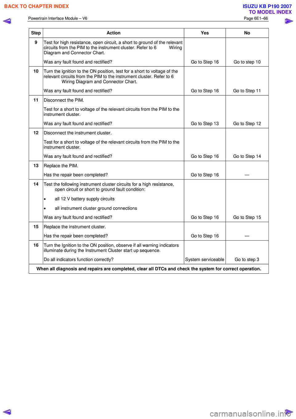
Step Action Yes No
9
Test for high resistance, open circuit, a short to ground of the relevant
circuits from the PIM to the instrument cluster. Refer to 6 W iring
Diagram and Connector Chart.
W as any fault found and rectified? Go to Step 16 Go to step 10
10
Turn the ignition to the ON position, test for a short to voltage of the
relevant circuits from the PIM to the instrument cluster. Refer to 6
W iring Diagram and Connector Chart.
W as any fault found and rectified? Go to Step 16 Go to Step 11
11
Disconnect the PIM.
Test for a short to voltage of the relevant circuits from the PIM to the
instrument cluster.
W as any fault found and rectified? Go to Step 13 Go to Step 12
12 Disconnect the instrument cluster.
Test for a short to voltage of the relevant circuits from the PIM to the
instrument cluster.
W as any fault found and rectified? Go to Step 16 Go to Step 14
13 Replace the PIM.
Has the repair been completed? Go to Step 16 —
14 Test the following instrument cluster circuits for a high resistance,
open circuit or short to ground fault condition:
• all 12 V battery supply circuits
• all instrument cluster ground connections
W as any fault found and rectified? Go to Step 16 Go to Step 15
15 Replace the instrument cluster.
Has the repair been completed? Go to Step 16 —
16 Turn the Ignition to the ON position, observe if all warning indicators
illuminate during the Instrument Cluster start up sequence.
Do all indicators function correctly? System serviceable Go to step 3
When all diagnosis and repairs are completed, clear all DTCs and check the system for correct operation.
BACK TO CHAPTER INDEX
TO MODEL INDEX
ISUZU KB P190 2007
Page 3741 of 6020
Powertrain Interface Module – V6 Page 6E1–80
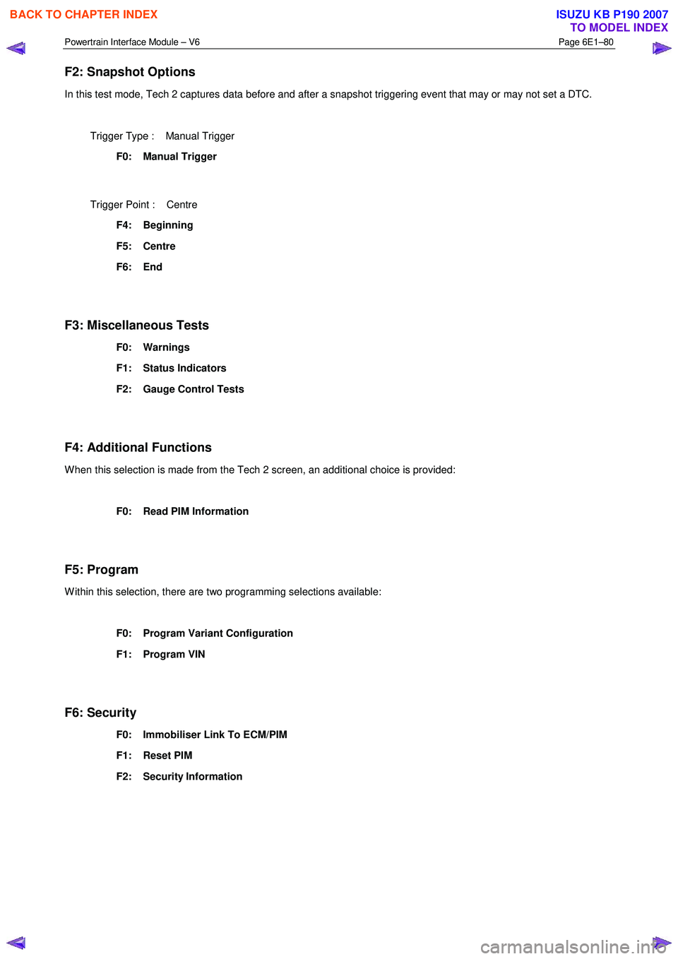
F2: Snapshot Options
In this test mode, Tech 2 captures data before and after a snapshot triggering event that may or may not set a DTC.
Trigger Type : Manual Trigger
F0: Manual Trigger
Trigger Point : Centre
F4: Beginning
F5: Centre
F6: End
F3: Miscellaneous Tests
F0: Warnings
F1: Status Indicators
F2: Gauge Control Tests
F4: Additional Functions
W hen this selection is made from the Tech 2 screen, an additional choice is provided:
F0: Read PIM Information
F5: Program
W ithin this selection, there are two programming selections available:
F0: Program Variant Configuration
F1: Program VIN
F6: Security
F0: Immobiliser Link To ECM/PIM
F1: Reset PIM
F2: Security Information
BACK TO CHAPTER INDEX
TO MODEL INDEX
ISUZU KB P190 2007
Page 3743 of 6020
Powertrain Interface Module – V6 Page 6E1–82
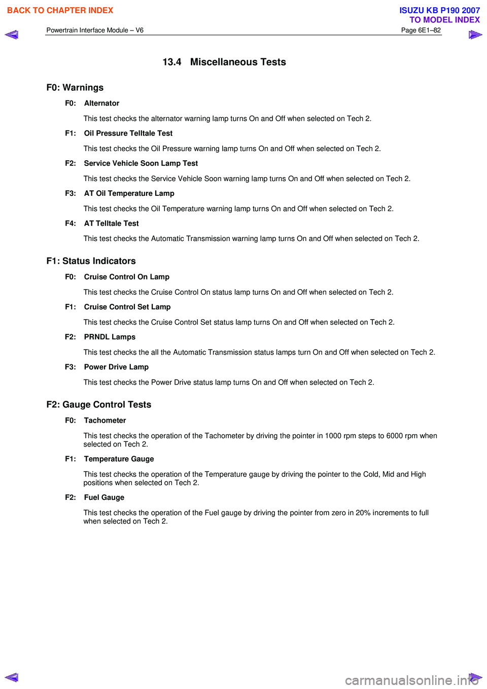
13.4 Miscellaneous Tests
F0: Warnings
F0: Alternator
This test checks the alternator warning lamp turns On and Off when selected on Tech 2.
F1: Oil Pressure Telltale Test
This test checks the Oil Pressure warning lamp turns On and Off when selected on Tech 2.
F2: Service Vehicle Soon Lamp Test
This test checks the Service Vehicle Soon warning lamp turns On and Off when selected on Tech 2.
F3: AT Oil Temperature Lamp
This test checks the Oil Temperature warning lamp turns On and Off when selected on Tech 2.
F4: AT Telltale Test
This test checks the Automatic Transmission warning lamp turns On and Off when selected on Tech 2.
F1: Status Indicators
F0: Cruise Control On Lamp
This test checks the Cruise Control On status lamp turns On and Off when selected on Tech 2.
F1: Cruise Control Set Lamp
This test checks the Cruise Control Set status lamp turns On and Off when selected on Tech 2.
F2: PRNDL Lamps
This test checks the all the Automatic Transmission status lamps turn On and Off when selected on Tech 2.
F3: Power Drive Lamp
This test checks the Power Drive status lamp turns On and Off when selected on Tech 2.
F2: Gauge Control Tests
F0: Tachometer
This test checks the operation of the Tachometer by driving the pointer in 1000 rpm steps to 6000 rpm when
selected on Tech 2.
F1: Temperature Gauge
This test checks the operation of the Temperature gauge by driving the pointer to the Cold, Mid and High
positions when selected on Tech 2.
F2: Fuel Gauge
This test checks the operation of the Fuel gauge by driving the pointer from zero in 20% increments to full when selected on Tech 2.
BACK TO CHAPTER INDEX
TO MODEL INDEX
ISUZU KB P190 2007
Page 3783 of 6020
Automatic Transmission – 4L60E – General Information Page 7C1–23
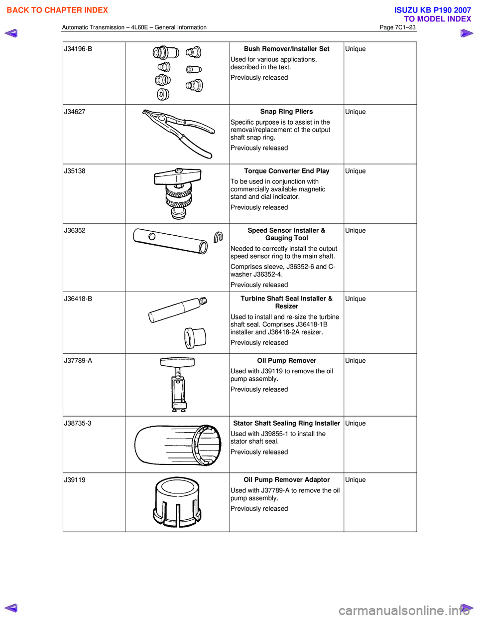
J34196-B
Bush Remover/Installer Set
Used for various applications,
described in the text.
Previously released Unique
J34627
Snap Ring Pliers
Specific purpose is to assist in the
removal/replacement of the output
shaft snap ring.
Previously released Unique
J35138
Torque Converter End Play
To be used in conjunction with
commercially available magnetic
stand and dial indicator.
Previously released Unique
J36352 Speed Sensor Installer &
Gauging Tool
Needed to correctly install the output
speed sensor ring to the main shaft.
Comprises sleeve, J36352-6 and C-
washer J36352-4.
Previously released Unique
J36418-B
Turbine Shaft Seal Installer &
Resizer
Used to install and re-size the turbine
shaft seal. Comprises J36418-1B
installer and J36418-2A resizer.
Previously released Unique
J37789-A
Oil Pump Remover
Used with J39119 to remove the oil
pump assembly.
Previously released Unique
J38735-3 Stator Shaft Sealing Ring Installer
Used with J39855-1 to install the
stator shaft seal.
Previously released Unique
J39119
Oil Pump Remover Adaptor
Used with J37789-A to remove the oil
pump assembly.
Previously released Unique
BACK TO CHAPTER INDEX
TO MODEL INDEX
ISUZU KB P190 2007
Page 3785 of 6020
Automatic Transmission – 4L60E – General Information Page 7C1–25
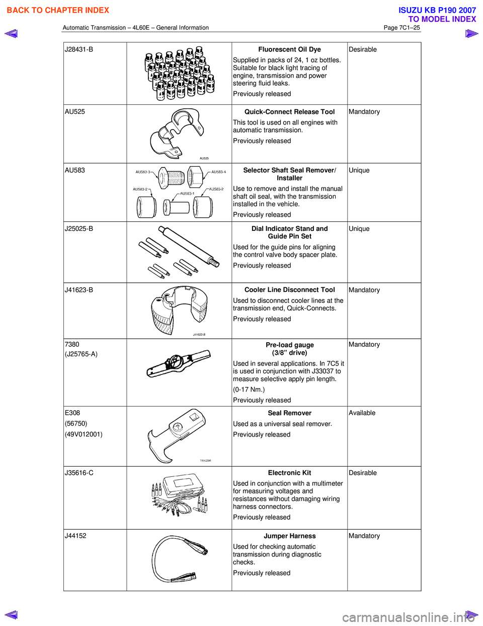
J28431-B
Fluorescent Oil Dye
Supplied in packs of 24, 1 oz bottles.
Suitable for black light tracing of
engine, transmission and power
steering fluid leaks.
Previously released Desirable
AU525
AU525 Quick-Connect Release Tool
This tool is used on all engines with
automatic transmission.
Previously released Mandatory
AU583 Selector Shaft Seal Remover/
Installer
Use to remove and install the manual
shaft oil seal, with the transmission
installed in the vehicle.
Previously released Unique
J25025-B
Dial Indicator Stand and
Guide Pin Set
Used for the guide pins for aligning
the control valve body spacer plate.
Previously released Unique
J41623-B
Cooler Line Disconnect Tool
Used to disconnect cooler lines at the
transmission end, Quick-Connects.
Previously released Mandatory
7380
(J25765-A)
Pre-load gauge
(3/8” drive)
Used in several applications. In 7C5 it
is used in conjunction with J33037 to
measure selective apply pin length.
(0-17 Nm.)
Previously released Mandatory
E308
(56750)
(49V012001)
Seal Remover
Used as a universal seal remover .
Previously released Available
J35616-C
Electronic Kit
Used in conjunction with a multimeter
for measuring voltages and
resistances without damaging wiring
harness connectors.
Previously released Desirable
J44152
Jumper Harness
Used for checking automatic
transmission during diagnostic
checks.
Previously released Mandatory
BACK TO CHAPTER INDEX
TO MODEL INDEX
ISUZU KB P190 2007
Page 3787 of 6020
Automatic Transmission – 4L60E – Electrical Diagnosis Page 7C2–1
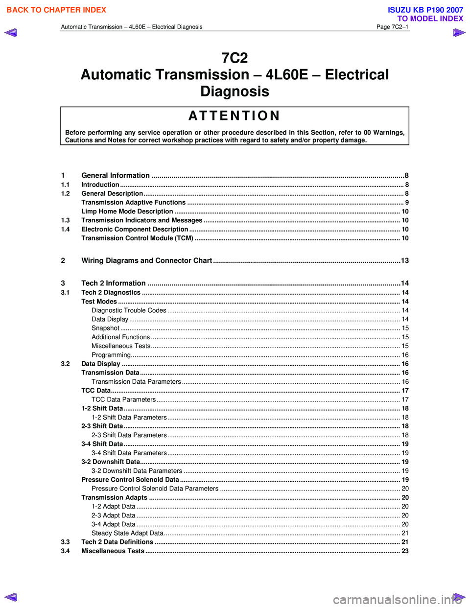
7C2
Diagnosis
ATTENTION
Before performing any service operation or other procedure described in this Section, refer to 00 Warnings, Cautions and Notes for correct workshop practices with regard to safety and/or property damage.
1 General Information ............................................................................................................ ...................8
1.1 Introduction ............................................................................................................................................................ 8
1.2 General Description ............................................................................................................................................... 8
Transmission Adaptive Functions ................................................................................................ ....................... 9
Limp Home Mode Description ............................................................................................................................ 10
1.3 Transmission Indicators and Messages ............................................................................................................ 10
1.4 Electronic Component Description ............................................................................................... ..................... 10
Transmission Control Module (TCM) ................................................................................................................. 10
2 Wiring Diagrams and Connector Chart ............................................................................................ ..13
3 Tech 2 Information ...............................................................................................................................14
3.1 Tech 2 Diagnostics .............................................................................................................................................. 14
Test Modes ........................................................................................................................................................... 14
Diagnostic Trouble Codes ....................................................................................................... ......................... 14
Data Display ..................................................................................................................................................... 14
Snapshot .......................................................................................................................................................... 15
Additional Functions ........................................................................................................... .............................. 15
Miscellaneous Tests ......................................................................................................................................... 15
Programming.................................................................................................................................................... 16
3.2 Data Display ......................................................................................................................................................... 16
Transmission Data .............................................................................................................. ................................. 16
Transmission Data Parameters ................................................................................................... ..................... 16
TCC Data............................................................................................................................................................... 17
TCC Data Parameters ............................................................................................................ .......................... 17
1-2 Shift Data ........................................................................................................................................................ 18
1-2 Shift Data Parameters ................................................................................................................................ 18
2-3 Shift Data ........................................................................................................................................................ 18
2-3 Shift Data Parameters ................................................................................................................................ 18
3-4 Shift Data ........................................................................................................................................................ 19
3-4 Shift Data Parameters ................................................................................................................................ 19
3-2 Downshift Data............................................................................................................................................... 19
3-2 Downshift Data Parameters ....................................................................................................................... 19
Pressure Control Solenoid Data ................................................................................................. ........................ 19
Pressure Control Solenoid Data Parameters ...................................................................................... ............. 20
Transmission Adapts .......................................................................................................................................... 20
1-2 Adapt Data ................................................................................................................................................. 20
2-3 Adapt Data ................................................................................................................................................. 20
3-4 Adapt Data ................................................................................................................................................. 20
Steady State Adapt Data ........................................................................................................ .......................... 21
3.3 Tech 2 Data Definitions ........................................................................................................ ............................... 21
3.4 Miscellaneous Tests ............................................................................................................................................ 23
Automatic Tra nsm ission – 4L60E – Electric al
BACK TO CHAPTER INDEX
TO MODEL INDEX
ISUZU KB P190 2007
Page 3796 of 6020
Automatic Transmission – 4L60E – Electrical Diagnosis Page 7C2–10
Limp Home Mode Description
If a major electrical system failure occurs which could affect vehicle safety or damage the transmission during normal
operation, the TCM enters a limp home mode. In the limp home mode, the transmission operates in the following
manner:
• The pressure control solenoid is off and the line pressure is at maximum to minimise clutch slippage.
• The TCC solenoid is off, therefore the torque converter clutch is disabled.
• The two shift solenoids are turned off. The transmission will operate in fourth gear if the vehicle has successfully
completed a 1-2 upshift in the current ignition cycle. If the vehicle has not completed a 1-2 upshift in the current
ignition cycle, the transmission will operate in third gear. If the transmission is operating in fourth gear, third gear
may be obtained if the engine is stopped briefly and re-started.
In limp home mode, the gear selector lever is ineffective at selecting forward gear ranges. In third or fourth gear, heat
builds up in the transmission quickly, particularly in stop and go traffic. Excessive heat build-up may cause transmission
failure if the vehicle is driven for extended distances in limp home mode.
1.3 Transmission Indicators and Messages
For information pertaining to the instrument cluster and the transmission information it displays, refer to the RA Rodeo
Owner Handbook.
1.4 Electronic Component Description
For all other electrical components not covered in this section, refer to General Motors Powertrain Group Electronically
Controlled Automatic Transmission Technician's Guide.
Transmission Control Module (TCM)
The Transmission Control Module (TCM) is located under the instrument panel, next to the brake pedal assembly and
connects directly to the transmission wiring harness. A single 49-way connector is used to make the connection between
the vehicle wiring harness and the TCM.
To access the connector for diagnosis:
1 Ensure the ignition switch is in the OFF position.
2 Disconnect the connector (1) from the transmission control module (TCM) (2) as follows, refer to Figure 7C2 – 2: a remove the securing pin (3),
b press the locking tab and swing the lever (4) to free the connector,
c remove the connector.
BACK TO CHAPTER INDEX
TO MODEL INDEX
ISUZU KB P190 2007
Page 3822 of 6020
Automatic Transmission – 4L60E – Electrical Diagnosis Page 7C2–36
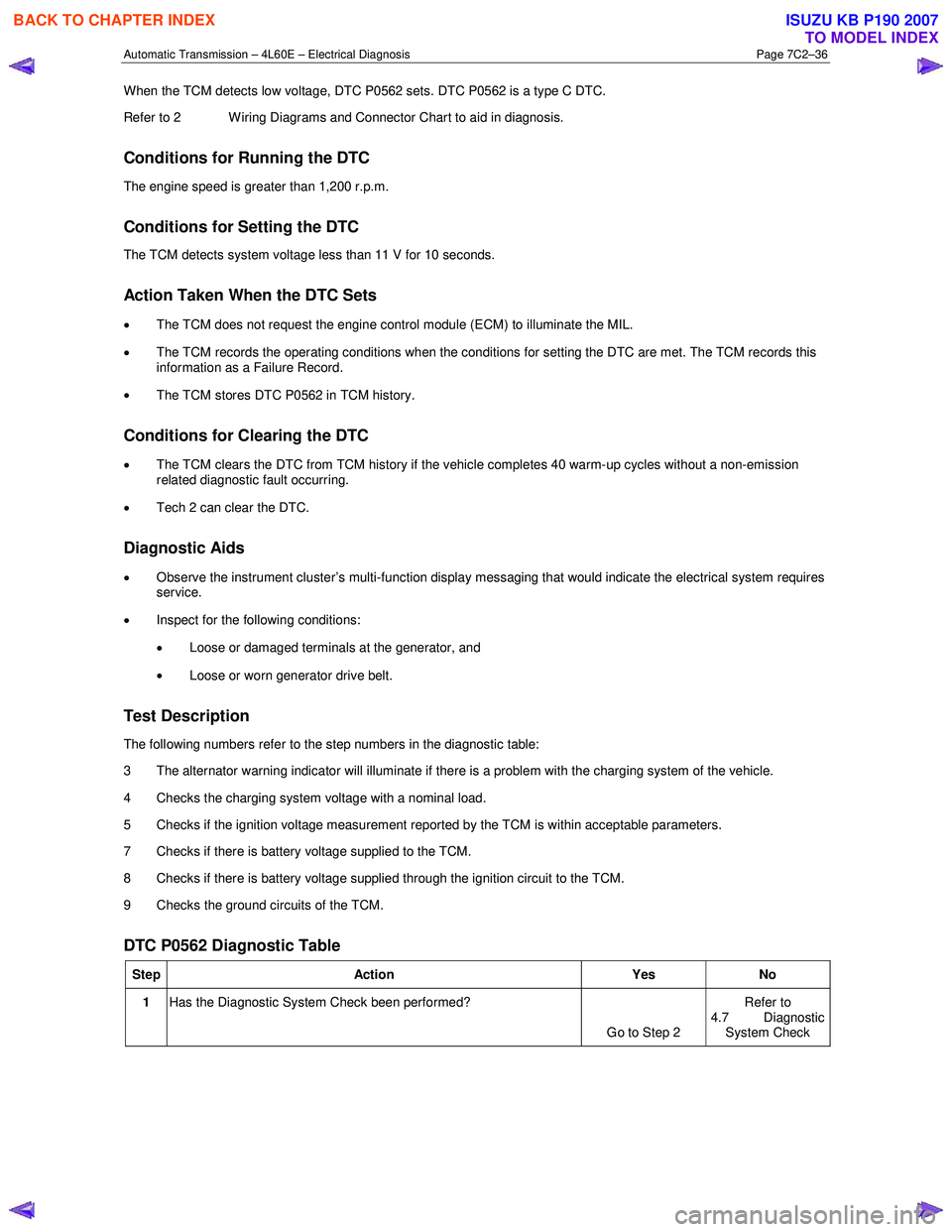
When the TCM detects low voltage, DTC P0562 sets. DTC P0562 is a type C DTC.
Refer to 2 W iring Diagrams and Connector Chart to aid in diagnosis.
Conditions for Running the DTC
The engine speed is greater than 1,200 r.p.m.
Conditions for Setting the DTC
The TCM detects system voltage less than 11 V for 10 seconds.
Action Taken When the DTC Sets
• The TCM does not request the engine control module (ECM) to illuminate the MIL.
• The TCM records the operating conditions when the conditions for setting the DTC are met. The TCM records this
information as a Failure Record.
• The TCM stores DTC P0562 in TCM history.
Conditions for Clearing the DTC
• The TCM clears the DTC from TCM history if the vehicle completes 40 warm-up cycles without a non-emission
related diagnostic fault occurring.
• Tech 2 can clear the DTC.
Diagnostic Aids
• Observe the instrument cluster’s multi-function display messaging that would indicate the electrical system requires
service.
• Inspect for the following conditions:
• Loose or damaged terminals at the generator, and
• Loose or worn generator drive belt.
Test Description
The following numbers refer to the step numbers in the diagnostic table:
3 The alternator warning indicator will illuminate if there is a problem with the charging system of the vehicle.
4 Checks the charging system voltage with a nominal load.
5 Checks if the ignition voltage measurement reported by the TCM is within acceptable parameters.
7 Checks if there is battery voltage supplied to the TCM.
8 Checks if there is battery voltage supplied through the ignition circuit to the TCM.
9 Checks the ground circuits of the TCM.
DTC P0562 Diagnostic Table
Step Action Yes No
1 Has the Diagnostic System Check been performed?
Go to Step 2 Refer to
4.7 Diagnostic
System Check
BACK TO CHAPTER INDEX
TO MODEL INDEX
ISUZU KB P190 2007