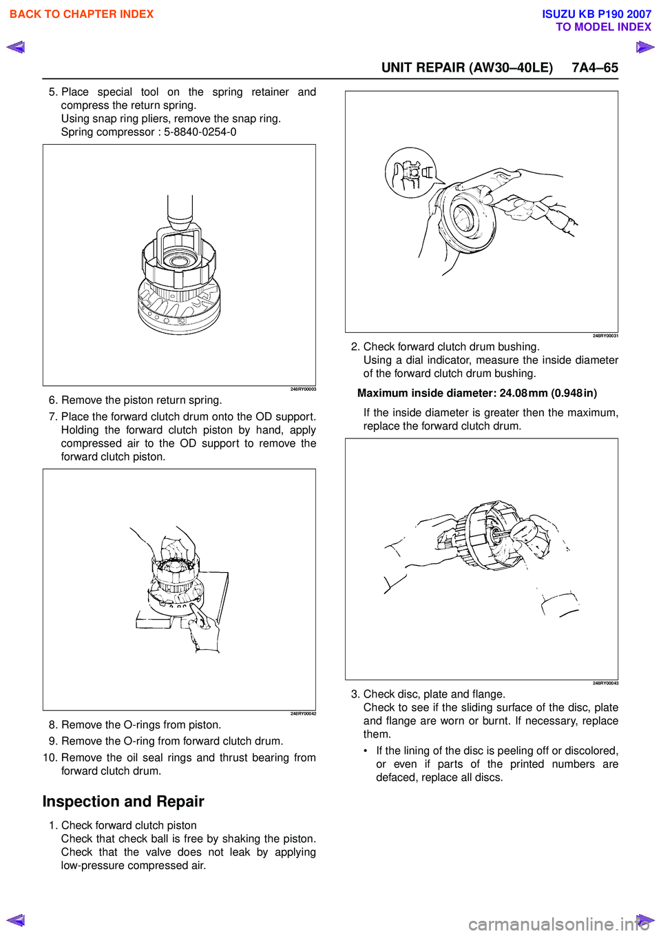
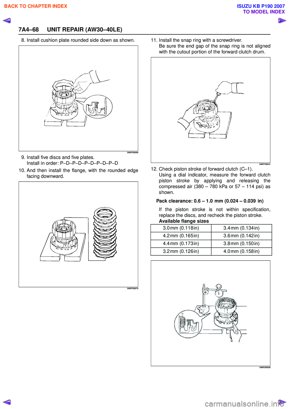
Page 4195 of 6020
7A4–60 UNIT REPAIR (AW30–40LE)
4. Check direct clutch drum bushing.Using a dial indicator, measure the inside diameter
of the clutch drum bushing.
Maximum inside diameter: 53.99 mm (2.1256 in) If the inside diamater is greater than the maximum,
replace the clutch drum.
248RY00032
Reassembly
1. Coat new O-rings with ATF and install them on the direct clutch piston.
2. Install direct clutch piston to direct clutch drum. Being careful not to damage the O-rings, press in
the direct clutch piston into the clutch drum, using
both hands.
248RY00033
3. Install piston return spring.
248RY00034
4. Compress piston return spring and install snap ring in groove.
Place special tool on the spring retainer, and
compress the return spring.
Install the snap ring with snap ring pliers.
Be sure the end gap of the snap ring is not
aligned with the spring retainer claw.
Spring compressor: 5-8840-0254-0
248RY00002
BACK TO CHAPTER INDEX
TO MODEL INDEX
ISUZU KB P190 2007
Page 4196 of 6020
UNIT REPAIR (AW30–40LE) 7A4–61
5. Install four plates and four discs.Install in order : P –D –P –D –P –D –P –D
P : Plate, D : Disc
248RY00062
6. Install the flange, with the flat side facing downward.
248RY00035
7. Install the snap ring with a screwdriver. Be sure the end gap of the snap ring is not aligned
with the cutout portion of the direct clutch drum.
248RY00036
8. Check piston stroke of direct clutch (C –2).
Place the direct clutch assembly onto the OD
support assembly.
248RY00029Using a dial indicator, measure the direct clutch
piston stroke by applying and releasing compressed
air (390 – 780 kPa or 57 – 114 psi) as shown.
Pack clearance: 0.5 – 0.8 mm (0.020 – 0.031 in)
If the piston stroke is not within specification,
replace the discs and recheck the piston stroke.
If the piston stroke is nonstandard, select another
flange.
BACK TO CHAPTER INDEX
TO MODEL INDEX
ISUZU KB P190 2007
Page 4199 of 6020
7A4–64 UNIT REPAIR (AW30–40LE)
Disassembly
Remove forward clutch assembly from direct clutch
assembly.
248RY00039
1. Place wooden blocks, etc. to prevent forward clutch shaft from touching the work stand, and place the
OD support on them.
Place the forward clutch onto the OD support and
remove the bearing and race.
248RY00048
2. Check piston stroke of forward clutch (C –1).
248R200008Using a dial indicator, measure the forward clutch
piston stroke by applying and releasing compressed
air (390 – 780 kPa or 57 – 114 psi) as shown.
Pack clearance: 0.6 – 1.0 mm (0.024 – 0.039 in)
3. Remove snap ring from clutch drum.
248RY00041
4. Remove the flange, disc and plate, and cushion plate.
BACK TO CHAPTER INDEX
TO MODEL INDEX
ISUZU KB P190 2007
Page 4200 of 6020

UNIT REPAIR (AW30–40LE) 7A4–65
5. Place special tool on the spring retainer andcompress the return spring.
Using snap ring pliers, remove the snap ring.
Spring compressor : 5-8840-0254-0
248RY00003
6. Remove the piston return spring.
7. Place the forward clutch drum onto the OD suppor t. Holding the forward clutch piston by hand, apply
compressed air to the OD support to remove the
forward clutch piston.
248RY00042
8. Remove the O-rings from piston.
9. Remove the O-ring from forward clutch drum.
10. Remove the oil seal rings and thrust bearing from forward clutch drum.
Inspection and Repair
1. Check forward clutch pistonCheck that check ball is free by shaking the piston.
Check that the valve does not leak by applying
low-pressure compressed air.
248RY00031
2. Check forward clutch drum bushing. Using a dial indicator, measure the inside diameter
of the forward clutch drum bushing.
Maximum inside diameter: 24.08 mm (0.948 in) If the inside diameter is greater then the maximum,
replace the forward clutch drum.
248RY00043
3. Check disc, plate and flange. Check to see if the sliding surface of the disc, plate
and flange are worn or burnt. If necessary, replace
them.
If the lining of the disc is peeling off or discolored,
or even if parts of the printed numbers are
defaced, replace all discs.
BACK TO CHAPTER INDEX
TO MODEL INDEX
ISUZU KB P190 2007
Page 4203 of 6020

7A4–68 UNIT REPAIR (AW30–40LE)
8. Install cushion plate rounded side down as shown.
248RY00069
9. Install five discs and five plates.Install in order: P –D –P –D –P –D –P –D –P –D
10. And then install the flange, with the rounded edge facing downward.
248RY00070
11. Install the snap ring with a screwdriver. Be sure the end gap of the snap ring is not aligned
with the cutout portion of the forward clutch drum.
248RY00041
12. Check piston stroke of forward clutch (C –1).
Using a dial indicator, measure the forward clutch
piston stroke by applying and releasing the
compressed air (380 – 780 kPa or 57 – 114 psi) as
shown.
Pack clearance: 0.6 – 1.0 mm (0.024 – 0.039 in)
If the piston stroke is not within specification,
replace the discs, and recheck the piston stroke.
Available flange sizes
248R200008
3.0 mm (0.118 in) 3.4 mm (0.134 in)
4.2 mm (0.165 in) 3.6 mm (0.142 in)
4.4 mm (0.173 in) 3.8 mm (0.150 in)
3.2 mm (0.126 in) 4.0 mm (0.158 in)
BACK TO CHAPTER INDEX
TO MODEL INDEX
ISUZU KB P190 2007
Page 4205 of 6020
7A4–70 UNIT REPAIR (AW30–40LE)
Front Planetary Gear
Disassembled View
RTW77ASF000201
EndOFCallout
Disassembly
1. Remove the race from front planetary ring gear.
2. Remove the thrust bearing and race from front planetary gear.
3. Remove the race (Metal), thrust bearing and race between front planetary ring gear and front
planetary gear.
Inspection and Repair
1. Check front planetary ring gear bushing Using a dial indicator, measure the inside diameter
of the front planetary ring gear bushing.
Maximum inside diameter: 24.08 mm (0.9480 in) If the inside diameter is greater than the maximum,
replace the front planetary ring gear.
247RY00021
Legend
(1) Front planetary ring gear
(2) Race
(3) Thrust bearing
(4) Race (5) Snap ring
(6) Front planetary gear
(7) Race
(8) Thrust bearing
BACK TO CHAPTER INDEX
TO MODEL INDEX
ISUZU KB P190 2007
Page 4208 of 6020
UNIT REPAIR (AW30–40LE) 7A4–73
Disassembly
1. Check operation of No.1 one-way clutchHold the planetary sun gear and turn the second
brake hub.
The second brake hub should turn freely clockwise
and should lock counterclockwise.
RUW37ASH004601
E ndOFCallout
2. Remove the one-way clutch and second brake hub.
3. Remove the trust washer (plastic).
4. Remove two oil seal rings (metal).
248RY00052
5. Remove the snap ring with snap ring pliers.
248RY00053
6. Remove the sun gear input drum.
7. Remove the snap ring from planetary sun gear.
Inspection and Repair
1. Check planetary sun gear bushing Using a dial indicator, measure the inside diameter
of the planetary sun gear bushing.
Maximum inside diameter: 27.08 mm (1.066 in) If the inside diameter is greater than the maximum,
replace the planetary sun gear.
248RY00054
Legend
(1) Free
(2) Lock
BACK TO CHAPTER INDEX
TO MODEL INDEX
ISUZU KB P190 2007
Page 4245 of 6020
7A1-6 CONSTRUCTION AND FUNCTION
ELECTRONIC CONTROL COMPONENTS LOCATION
4WD Only 4W D Only
Instrument panel (Meter)
Speed meter (2WD Only)
Shift position indicator lamp
POWER DRIVE, 3rd START
indicator lamp
A/T OIL TEMP indicator lamp
CHECK TRANS indicator lam
p
Brake pedal
Brake Switch
Transmission Control Module (TCM)
Electrical source
Ignition
Battery voltage
Speed sensor
Turbine sensor
Inhibitor switch
ATF thermo sensor
High clutch oil pressure switch
2-4 brake oil pressure switch
Low & Reverse brake oil pressure
switch
Line pressure solenoid
Low clutch solenoid
High clutch solenoid
2-4 brake solenoid
Low & Reverse brake solenoid
Lock-up solenoid
Transmission
Transfer Control Module
Transfer
4L mode switch
Engine
Engine speed sensor
Accelerator pedal Position Sensor
Engine Control Module (ECM)
Data link connector
Select lever
Power Drive
, 3rd Start select switch
Figure 3. Electronic Control Components Location
BACK TO CHAPTER INDEX
TO MODEL INDEX
ISUZU KB P190 2007