2007 ISUZU KB P190 indicator
[x] Cancel search: indicatorPage 4809 of 6020
CLUTCH 7C-31
Driven Plate Warpage
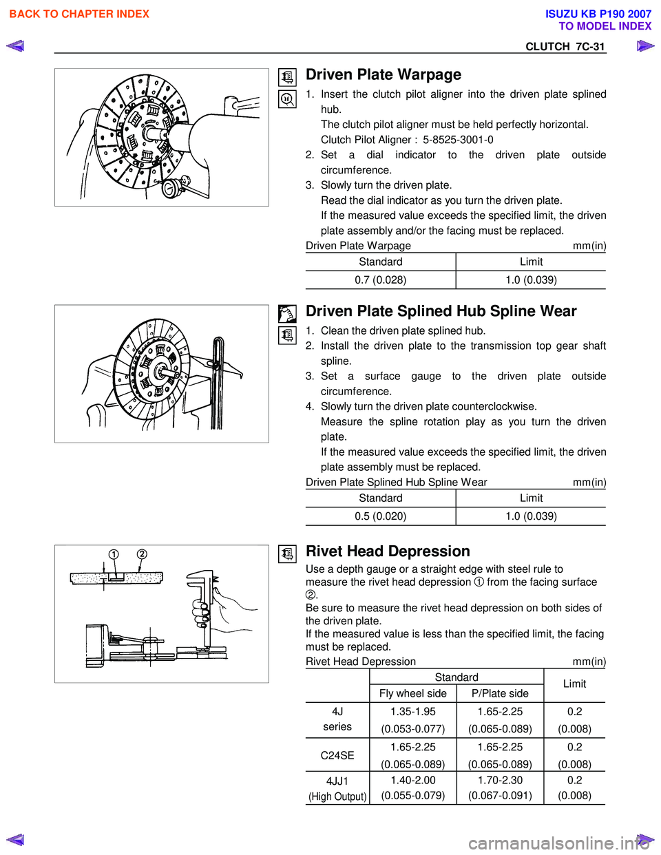
1. Insert the clutch pilot aligner into the driven plate splinedhub.
The clutch pilot aligner must be held perfectly horizontal.
Clutch Pilot Aligner : 5-8525-3001-0
2. Set a dial indicator to the driven plate outside circumference.
3. Slowly turn the driven plate.
Read the dial indicator as you turn the driven plate.
If the measured value exceeds the specified limit, the driven plate assembly and/or the facing must be replaced.
Driven Plate W arpage mm(in)
Standard Limit
0.7 (0.028)1.0 (0.039)
Driven Plate Splined Hub Spline Wear
1. Clean the driven plate splined hub.
2. Install the driven plate to the transmission top gear shaft spline.
3. Set a surface gauge to the driven plate outside circumference.
4. Slowly turn the driven plate counterclockwise.
Measure the spline rotation play as you turn the driven plate.
If the measured value exceeds the specified limit, the driven plate assembly must be replaced.
Driven Plate Splined Hub Spline W ear mm(in)
Standard Limit
0.5 (0.020)1.0 (0.039)
Rivet Head Depression
Use a depth gauge or a straight edge with steel rule to
measure the rivet head depression
1 from the facing surface
2.
Be sure to measure the rivet head depression on both sides of
the driven plate.
If the measured value is less than the specified limit, the facing
must be replaced.
Rivet Head Depression mm(in)
Standard
Fly wheel side P/Plate side Limit
4J
series 1.35-1.95
(0.053-0.077) 1.65-2.25
(0.065-0.089) 0.2
(0.008)
C24SE 1.65-2.25
(0.065-0.089) 1.65-2.25
(0.065-0.089) 0.2
(0.008)
4JJ1
(High Output)
1.40-2.00
(0.055-0.079) 1.70-2.30
(0.067-0.091) 0.2
(0.008)
BACK TO CHAPTER INDEX
TO MODEL INDEX
ISUZU KB P190 2007
Page 4814 of 6020
7C-36 CLUTCH
INSPECTION AND REPAIR
Make the necessary adjustments, repairs, and part replacements if excessive wear or damage is discovered during
inspection.
Cylinder Body
1. Clean the cylinder body.
2. Check the fluid return port for restrictions and clean it i
f
necessary.
Cylinder Bore and piston Clearance
1. Clean the cylinder body and the piston.
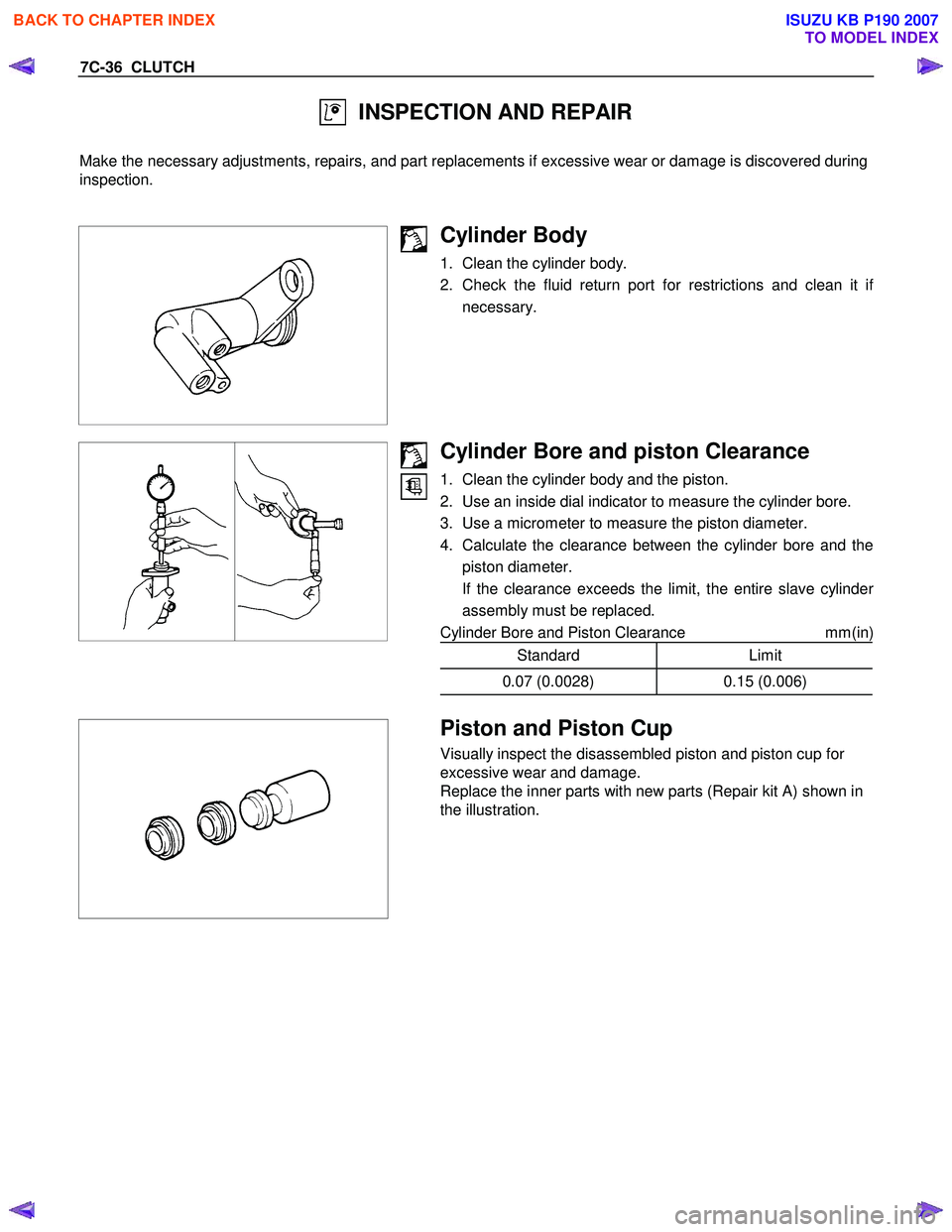
2. Use an inside dial indicator to measure the cylinder bore.
3. Use a micrometer to measure the piston diameter.
4. Calculate the clearance between the cylinder bore and the piston diameter.
If the clearance exceeds the limit, the entire slave cylinde
r
assembly must be replaced.
Cylinder Bore and Piston Clearance mm(in)
Standard Limit
0.07 (0.0028)0.15 (0.006)
Piston and Piston Cup
Visually inspect the disassembled piston and piston cup for
excessive wear and damage.
Replace the inner parts with new parts (Repair kit A) shown in
the illustration.
BACK TO CHAPTER INDEX
TO MODEL INDEX
ISUZU KB P190 2007
Page 4833 of 6020
TRANSFER CASE 7D-3
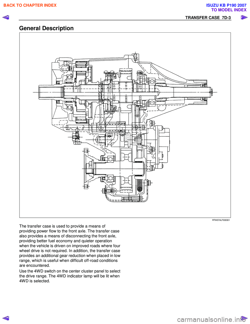
General Description
RTW 57ALF000301
The transfer case is used to provide a means of
providing power flow to the front axle. The transfer case
also provides a means of disconnecting the front axle,
providing better fuel economy and quieter operation
when the vehicle is driven on improved roads where fou
r
wheel drive is not required. In addition, the transfer case
provides an additional gear reduction when placed in lo
w
range, which is useful when difficult off-road conditions
are encountered.
Use the 4W D switch on the center cluster panel to select
the drive range. The 4W D indicator lamp will be lit when
4W D is selected.
BACK TO CHAPTER INDEX
TO MODEL INDEX
ISUZU KB P190 2007
Page 4842 of 6020
7D-12 TRANSFER CASE
Removal
NOTE: Before removing transmission and transfer
assembly from vehicle, change the transfer mode to
2W D using the 4W D push button switch on dash panel.
1. Disconnect battery ground cable.
2. Raise and support vehicle with suitable stands. Drain
transfer case fluid.
3. Remove rear propeller shaft and front propeller shaft.
NOTE: Apply alignment marks on the flange at both front
and rear sides.
4. Disconnect harness connectors and clip.
Connector: transfer switch, 2W D-4W D actuator,
speed sensor.
NOTE: Avoid turning the vehicle ignition switch to the ON
position when the 2W D-4W D connector is removed
(battery connected).
If the ignition switch must be turned to the ON position,
the controller must first be removed (memory must be
cleared because the CHECK 4W D INDICATOR will
light).
5. Remove transfer case assembly from the vehicle.
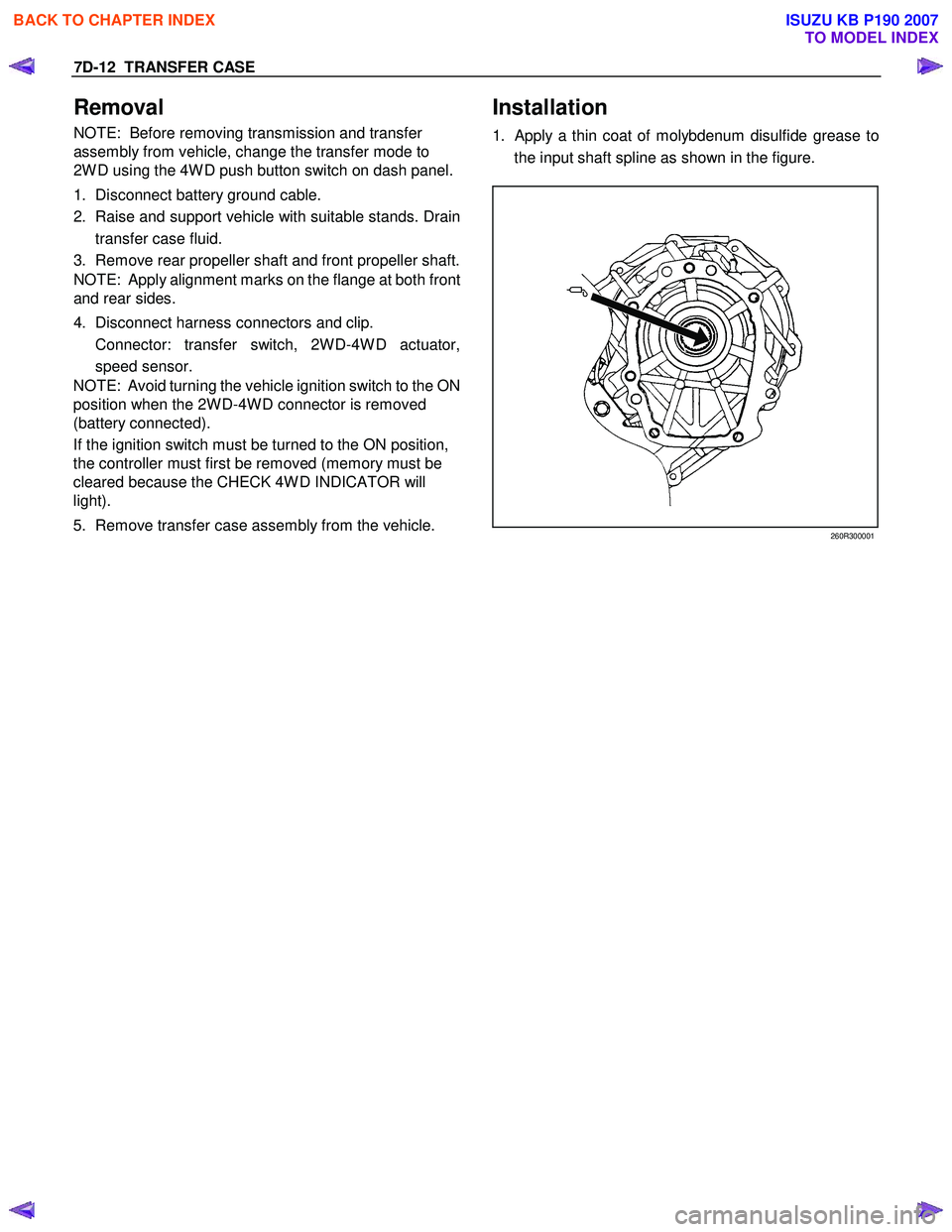
Installation
1. Apply a thin coat of molybdenum disulfide grease to
the input shaft spline as shown in the figure.
260R300001
BACK TO CHAPTER INDEX
TO MODEL INDEX
ISUZU KB P190 2007
Page 4858 of 6020
7D-28 TRANSFER CASE
Oil Pump
• Remove foreign materials from the strainer. If the
strainer is damaged, replace it.
If the area into which the shaft is inserted is excessively
worn or damaged, replace the oil pump assembly.
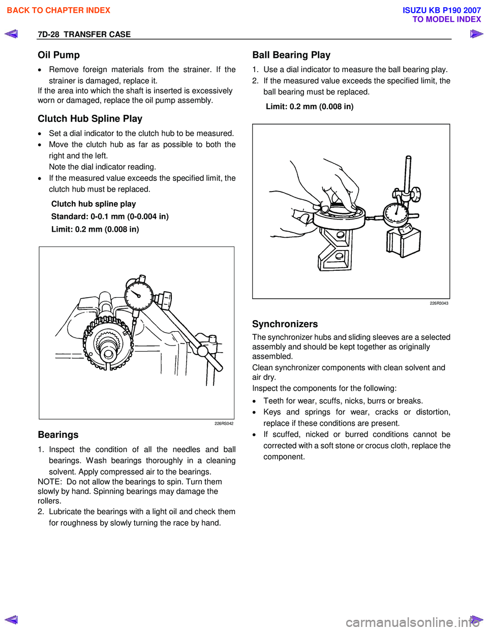
Clutch Hub Spline Play
• Set a dial indicator to the clutch hub to be measured.
• Move the clutch hub as far as possible to both the
right and the left.
Note the dial indicator reading.
• If the measured value exceeds the specified limit, the
clutch hub must be replaced.
Clutch hub spline play
Standard: 0-0.1 mm (0-0.004 in)
Limit: 0.2 mm (0.008 in)
226RS042
Bearings
1. Inspect the condition of all the needles and ball
bearings. W ash bearings thoroughly in a cleaning
solvent. Apply compressed air to the bearings.
NOTE: Do not allow the bearings to spin. Turn them
slowly by hand. Spinning bearings may damage the
rollers.
2. Lubricate the bearings with a light oil and check them
for roughness by slowly turning the race by hand.
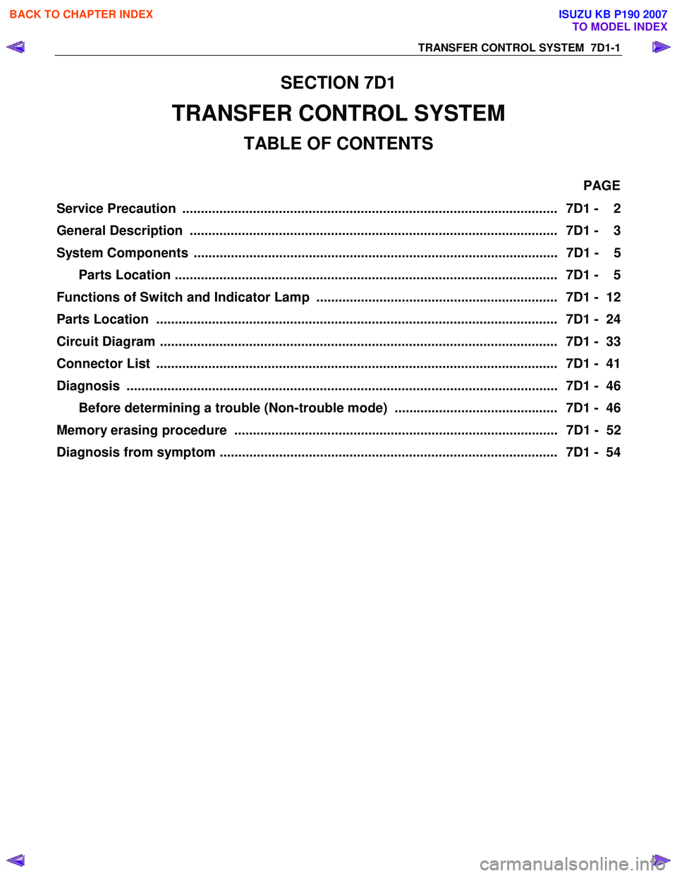
Ball Bearing Play
1. Use a dial indicator to measure the ball bearing play.
2. If the measured value exceeds the specified limit, the
ball bearing must be replaced.
Limit: 0.2 mm (0.008 in)
226R3043
Synchronizers
The synchronizer hubs and sliding sleeves are a selected
assembly and should be kept together as originally
assembled.
Clean synchronizer components with clean solvent and
air dry.
Inspect the components for the following:
• Teeth for wear, scuffs, nicks, burrs or breaks.
• Keys and springs for wear, cracks or distortion,
replace if these conditions are present.
• If scuffed, nicked or burred conditions cannot be
corrected with a soft stone or crocus cloth, replace the
component.
BACK TO CHAPTER INDEX
TO MODEL INDEX
ISUZU KB P190 2007
Page 4875 of 6020
TRANSFER CONTROL SYSTEM 7D1-1
SECTION 7D1
TRANSFER CONTROL SYSTEM
TABLE OF CONTENTS
PAGE
Service Precaution ..................................................................................................... 7D1 - 2
General Description ................................................................................................... 7D1 - 3
System Components .................................................................................................. 7D1 - 5 Parts Location ....................................................................................................... 7D1 - 5
Functions of Switch and Indicator Lamp ................................................................. 7D1 - 12
Parts Location ............................................................................................................ 7D1 - 24
Circuit Diagram ........................................................................................................... 7D1 - 33
Connector List ............................................................................................................ 7D1 - 41
Diagnosis .................................................................................................................... 7D1 - 46
Before determining a trouble (Non-trouble mode) ............................................ 7D1 - 46
Memory erasing procedure ....................................................................................... 7D1 - 52
Diagnosis from symptom ........................................................................................... 7D1 - 54
BACK TO CHAPTER INDEX
TO MODEL INDEX
ISUZU KB P190 2007
Page 4878 of 6020
7D1-4 TRANSFER CONTROL SYSTEM
Summary of transfer control system
The transfer control system switches between the 2-wheel
drive (2H), 4-wheel drive high-speed (4H), 4-wheel drive low-
speed (4L), and neutral positions electrically when the driver
operates the switches.
This system has following functions.
1. Connection or disconnection of drive force distribution to the
front wheel front shaft (axle shaft). (The drive force
distribution to the front propeller is connected o
r
disconnected with the motor actuator.)
2. Try to repeat the connection or disconnection of the front wheel drive function as described above.
3. Option: Shift on the fly type only.
Instruction of connection or disconnection of the drive force transmission between the front wheel axle (axle shaft) and
front wheel. (The motor actuator connects or disconnects
the left front wheel and front wheel axle (axle shaft).)
4. Shifting of auxiliary transmission gears, connection o
r
disconnection of wheel and engine drive force (4H, 4L,
neutral).
5. Operation of the indicator on the instrument panel.
6. Transmission of the position signal to other controllers.
BACK TO CHAPTER INDEX
TO MODEL INDEX
ISUZU KB P190 2007
Page 4880 of 6020
7D1-6 TRANSFER CONTROL SYSTEM
the 4×2 - 4 ×4 shift rod. W hen moving in 4 ×2 direction, a spring
standby mechanism is provided between the rod and sleeve so
that the rod is positioned at the 4 ×2 position, while the sleeve is
at the 4 ×4 position.
This mechanism is provided to protect the shift mechanism
from the force and to prevent movement of the sleeve
(torsional torque etc. of the drive system). By releasing the
preventive force, the sleeve can move to the 4 ×2 state by the
spring force.
Neutral switch
The neutral switch detects the movement of the shift rod
driving the high-low sleeve.
PUSH close is achieved with the PUSH close switch when the
shift rod is positioned between the High and the Low, at the
neutral state.
High-Low Sleeve & Arm
The spring standby mechanism is provided for the high-low
sleeve in both directions of the high-low shift rod. Therefore,
the rod position and the actual sleeve position may be offset in
some cases.
This system is provided to protect the shift mechanism from a
collision due to coincidence of the high and low phases of the
engaged splines. By giving rotational force to the preventing
phase coincidence, the splines are moved to the proper
engagement position by the spring force.
Shift actuator
The output shaft is rotated by the built-in motor and the transfer
position is switched.
Detection (limit) switches to detect the rotating angle of the
output shaft that is provided to the actuator at 4 positions.
These are connected to the transfer controller through the
vehicle harness to constantly transmit the actuator operating
angle and changes in its transfer status.
7B4-PDF2
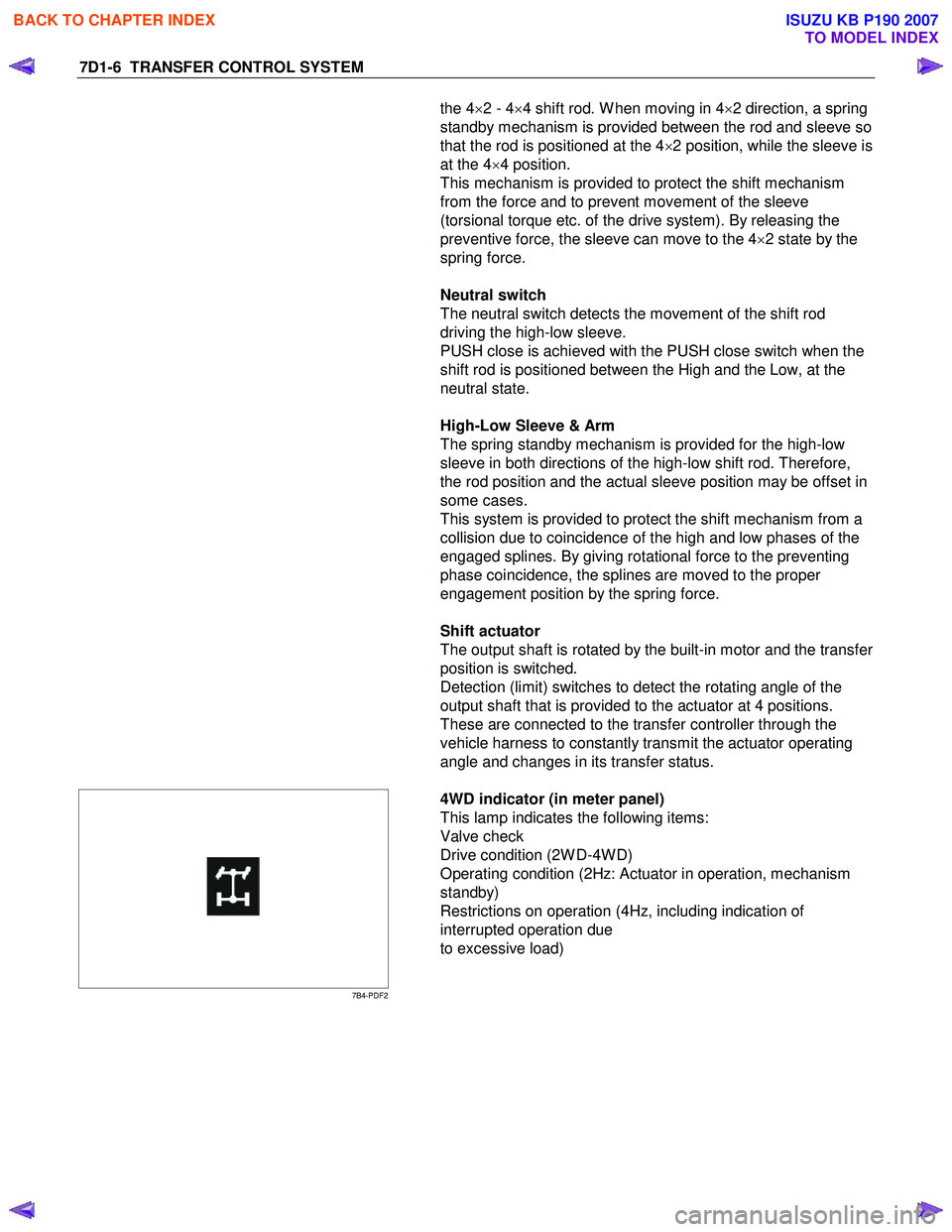
4WD indicator (in meter panel)
This lamp indicates the following items:
Valve check
Drive condition (2W D-4W D)
Operating condition (2Hz: Actuator in operation, mechanism
standby)
Restrictions on operation (4Hz, including indication of
interrupted operation due
to excessive load)
BACK TO CHAPTER INDEX
TO MODEL INDEX
ISUZU KB P190 2007