Page 5289 of 6020
ELECTRICAL-BODY AND CHASSIS 8A-351
WARNING AND INDICATOR LIGHT
1. When the parking brake lever is pulled, the brake indicator light does not light up
Checkpoint Trouble Cause Countermeasure
Replace or reinstall the bulb
Bulb burned out or loose
contact
NG
Adjust or replace the parking
brake SW .
Parking brake SW . installation
position and function
Incorrect SW . adjustment or
poor SW . point contact
Continuity between the
parking brake SW . connector
1
C39 (stick type), 1 R4
(lev er type), and 4
B23
(C24SE : 9
B23 )
Repair open circuit or
connector contact
Open circuit or poor connector
contact
NG
NG
OK
OK
Brake indicator light bulb
continuity
NG
OK
Continuity between the
parking brake SW . connector
1
C39 (stick type), 1 R4
(lev er type) and the ground
when the parking brake is
operated
Replace the parking brake
SW .
Parking brake SW .
malfunction
BACK TO CHAPTER INDEX TO MODEL INDEXISUZU KB P190 2007
Page 5290 of 6020
8A-352 ELECTRICAL-BODY AND CHASSIS
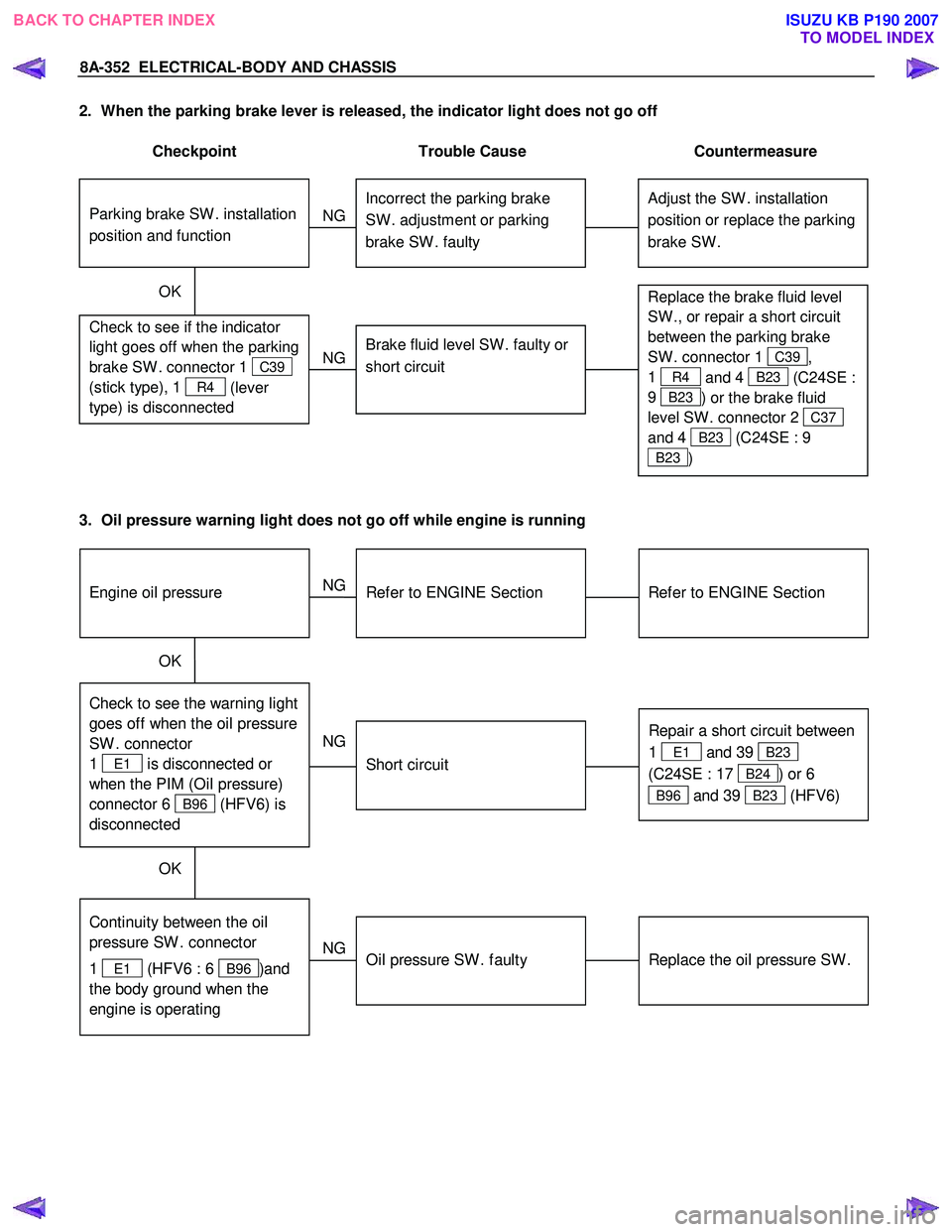
2. When the parking brake lever is released, the indicator light does not go off
Checkpoint Trouble Cause Countermeasure
Adjust the SW . installation
position or replace the parking
brake SW . Incorrect the parking brake
SW . adjustment or parking
brake SW . faulty
NG
Thermo unit malfunction
Replace the brake fluid level
SW ., or repair a short circuit
between the parking brake
SW . connector 1
C39,
1
R4 and 4 B23 (C24SE :
9
B23 ) or the brake fluid
level SW . connector 2
C37
and 4
B23 (C24SE : 9
B23 )
Check to see if the indicator
light goes off when the parking
brake SW . connector 1
C39
(stick type), 1
R4 (lever
type) is disconnected
Brake fluid level SW . faulty or
short circuit
NG
OK
Parking brake SW . installation
position and function
3. Oil pressure warning light does not go off while engine is running
Refer to ENGINE Section
Refer to ENGINE Section
NG Thermo unit malfunction
Check to see the warning light
goes off when the oil pressure
SW . connector
1
E1 is disconnected or
when the PIM (Oil pressure)
connector 6
B96 (HFV6) is
disconnected
Repair a short circuit between
1
E1 and 39 B23
(C24SE : 17
B24) or 6
B96 and 39 B23 (HFV6)
Short circuit
NG
OK
Replace the oil pressure SW .
Continuity between the oil
pressure SW . connector
1
E1 (HFV6 : 6 B96 )and
the body ground when the
engine is operating
Oil pressure SW . faulty
NG
OK
Engine oil pressure
BACK TO CHAPTER INDEX TO MODEL INDEXISUZU KB P190 2007
Page 5294 of 6020
8A-356 ELECTRICAL-BODY AND CHASSIS
INSPECTION AND REPAIR
METER AND INDICATOR LIGHT LAYOUT
Without tachometer (4JJ1-TC/4JK1-TC)
RTW 78AMF000501
With tachometer (4JJ1-TC/4JK1-TC)
RTW 78AMF000101
BACK TO CHAPTER INDEX TO MODEL INDEXISUZU KB P190 2007
Page 5300 of 6020
8A-362 ELECTRICAL-BODY AND CHASSIS
Tachometer Off-Vehicle Inspection
Remove the tachometer from the meter assembly and
measure the resistance value and the current consumption
between each terminal.
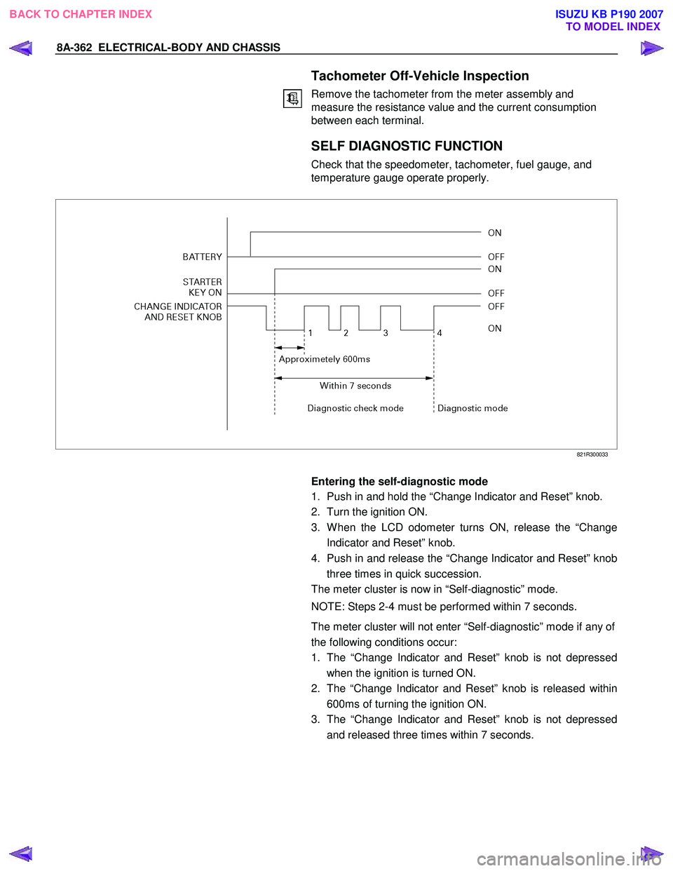
SELF DIAGNOSTIC FUNCTION
Check that the speedometer, tachometer, fuel gauge, and
temperature gauge operate properly.
821R300033
Entering the self-diagnostic mode
1. Push in and hold the “Change Indicator and Reset” knob.
2. Turn the ignition ON.
3. W hen the LCD odometer turns ON, release the “Change Indicator and Reset” knob.
4. Push in and release the “Change Indicator and Reset” knob three times in quick succession.
The meter cluster is now in “Self-diagnostic” mode.
NOTE: Steps 2-4 must be performed within 7 seconds.
The meter cluster will not enter “Self-diagnostic” mode if any of
the following conditions occur:
1. The “Change Indicator and Reset” knob is not depressed when the ignition is turned ON.
2. The “Change Indicator and Reset” knob is released within 600ms of turning the ignition ON.
3. The “Change Indicator and Reset” knob is not depressed and released three times within 7 seconds.
BACK TO CHAPTER INDEX TO MODEL INDEXISUZU KB P190 2007
Page 5301 of 6020
ELECTRICAL-BODY AND CHASSIS 8A-363
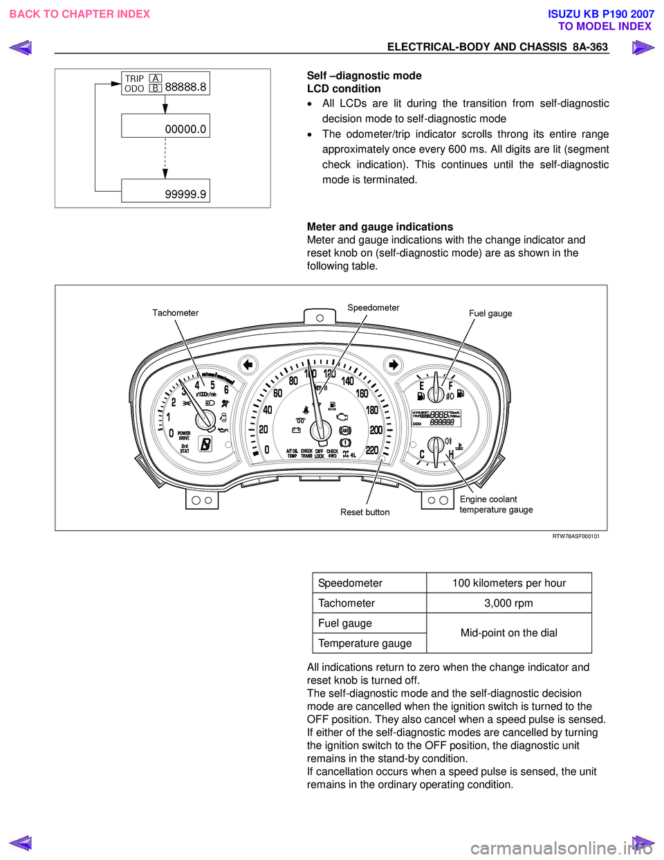
Self –diagnostic mode
LCD condition
• All LCDs are lit during the transition from self-diagnostic
decision mode to self-diagnostic mode
• The odometer/trip indicator scrolls throng its entire range
approximately once every 600 ms. All digits are lit (segment
check indication). This continues until the self-diagnostic
mode is terminated.
Meter and gauge indications
Meter and gauge indications with the change indicator and
reset knob on (self-diagnostic mode) are as shown in the
following table.
RTW 78ASF000101
Speedometer 100 kilometers per hour
Tachometer 3,000 rpm
Fuel gauge
Temperature gauge Mid-point on the dial
All indications return to zero when the change indicator and
reset knob is turned off.
The self-diagnostic mode and the self-diagnostic decision
mode are cancelled when the ignition switch is turned to the
OFF position. They also cancel when a speed pulse is sensed.
If either of the self-diagnostic modes are cancelled by turning
the ignition switch to the OFF position, the diagnostic unit
remains in the stand-by condition.
If cancellation occurs when a speed pulse is sensed, the unit
remains in the ordinary operating condition.
BACK TO CHAPTER INDEX TO MODEL INDEXISUZU KB P190 2007
Page 5303 of 6020
ELECTRICAL-BODY AND CHASSIS 8A-365
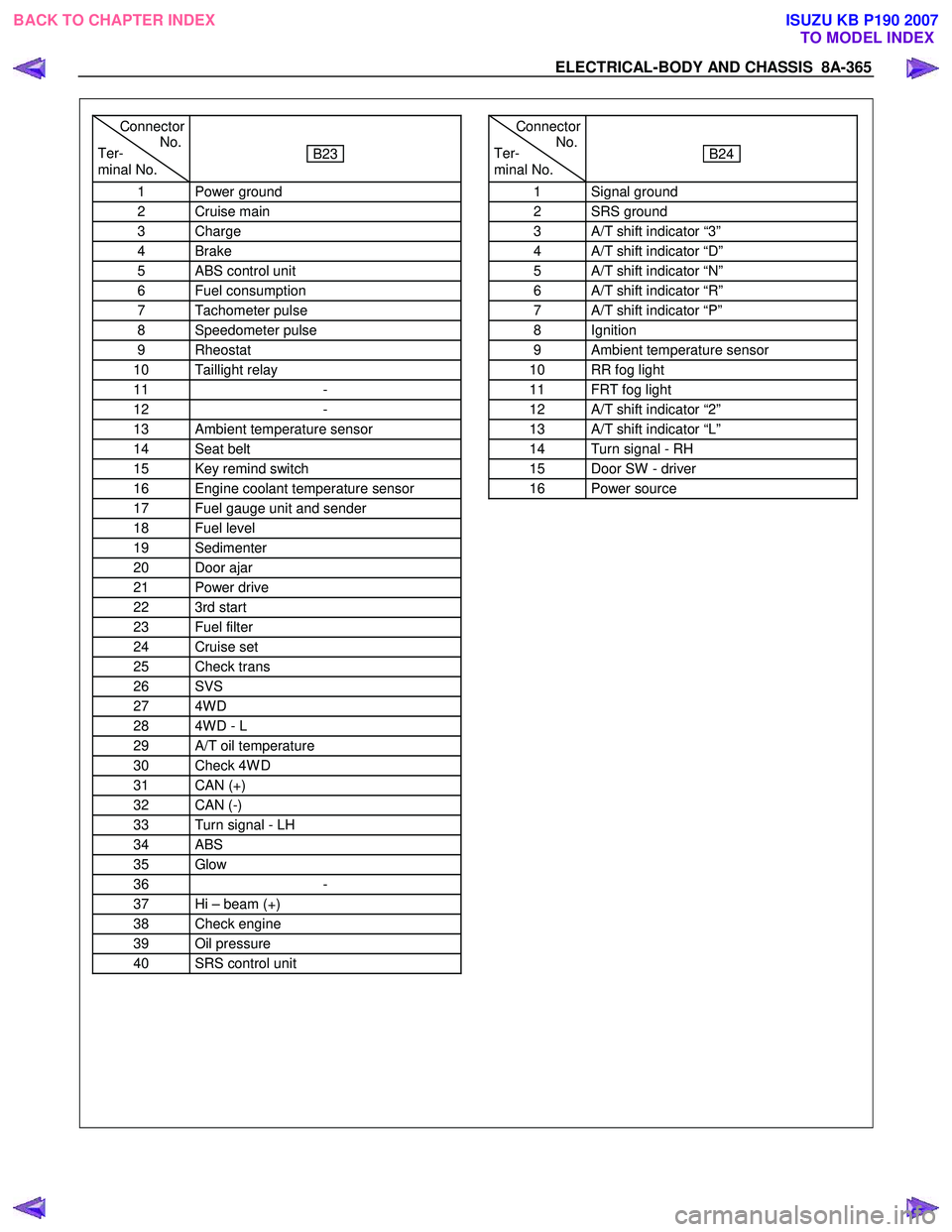
Connector
Ter- No.
minal No.
B23
1 Power ground
2 Cruise main
3 Charge
4 Brake
5 ABS control unit
6 Fuel consumption
7 Tachometer pulse
8 Speedometer pulse
9 Rheostat
10 Taillight relay
11 -
12 -
13 Ambient temperature sensor
14 Seat belt
15 Key remind switch
16 Engine coolant temperature sensor
17 Fuel gauge unit and sender
18 Fuel level
19 Sedimenter
20 Door ajar
21 Power drive
22 3rd start
23 Fuel filter
24 Cruise set
25 Check trans
26 SVS
27 4W D
28 4W D - L
29 A/T oil temperature
30 Check 4W D
31 CAN (+)
32 CAN (-)
33 Turn signal - LH
34 ABS
35 Glow
36 -
37 Hi – beam (+)
38 Check engine
39 Oil pressure
40 SRS control unit
Connector
Ter- No.
minal No.
B24
1 Signal ground
2 SRS ground
3 A/T shift indicator “3”
4 A/T shift indicator “D”
5 A/T shift indicator “N”
6 A/T shift indicator “R”
7 A/T shift indicator “P”
8 Ignition
9 Ambient temperature sensor
10 RR fog light
11 FRT fog light
12 A/T shift indicator “2”
13 A/T shift indicator “L”
14 Turn signal - RH
15 Door SW - driver
16 Power source
BACK TO CHAPTER INDEX TO MODEL INDEXISUZU KB P190 2007
Page 5305 of 6020
ELECTRICAL-BODY AND CHASSIS 8A-367
Connector No. B24 SOUTH
AFRICA SAUDI
ARABIA ISRAEL EUROPE OTHER
Terminal Connector place
4JJ1-TC HFV6 4JA1T(L) HFV6 4JJ1-TC HFV6 RHD LHD G.EXP
RHD 4JJ1-TC
C24SE
AUSTRALIAHFV6AUSTRALIA
1 Signal ground
2 SRS ground
3 A/T shift indicator
“3” ―
4 A/T shift indicator
“D” ―
5 A/T shift indicator
“N” ―
6 A/T shift indicator
“R” ―
7 A/T shift indicator
“P” ―
8 Ignition
9 Ambient
temperature sensor ―
10 RR fog light
― ― ― ― ― ―
―
― ― ―
11 FRT fog light
― ― ― ― ―
― ―
12 A/T shift indicator
“2” ―
13 A/T shift indicator
“L” ―
14 Turn signal - RH
15 Door SW - driver
16 Power source
BACK TO CHAPTER INDEX TO MODEL INDEXISUZU KB P190 2007
Page 5307 of 6020
ELECTRICAL-BODY AND CHASSIS 8A-369
Low Fuel Indicator Light
1. Disconnect the fuel gauge unit wire connector.
2. Turn the key switch on. Check that the bulb lights.
If operation is not correct, remove and check the bulb or circuit.
or If check whether low fuel turns on fuel input (B-24) at the
time of open and key on.
∗ meter is check at low fuel
RTW 78ASH001501
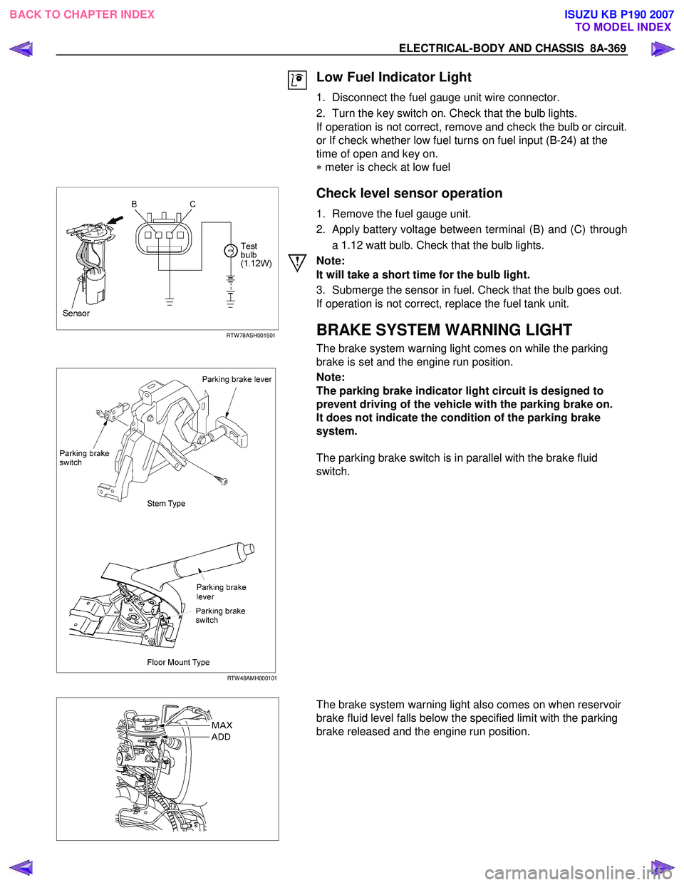
Check level sensor operation
1. Remove the fuel gauge unit.
2. Apply battery voltage between terminal (B) and (C) through a 1.12 watt bulb. Check that the bulb lights.
Note:
It will take a short time for the bulb light.
3. Submerge the sensor in fuel. Check that the bulb goes out.
If operation is not correct, replace the fuel tank unit.
BRAKE SYSTEM WARNING LIGHT
The brake system warning light comes on while the parking
brake is set and the engine run position.
RTW 48AMH000101
Note:
The parking brake indicator light circuit is designed to
prevent driving of the vehicle with the parking brake on.
It does not indicate the condition of the parking brake
system.
The parking brake switch is in parallel with the brake fluid
switch.
The brake system warning light also comes on when reservoir
brake fluid level falls below the specified limit with the parking
brake released and the engine run position.
BACK TO CHAPTER INDEX TO MODEL INDEXISUZU KB P190 2007