2007 ISUZU KB P190 indicator
[x] Cancel search: indicatorPage 5482 of 6020
8A-544 ELECTRICAL-BODY AND CHASSIS
Keyless Entry System
General Description
The system’s main features are summarized as follows.
・ Keyless entry with visual feedback
・ Highly secure encrypted transmission format
incorporating rolling code strategy
・ Field programmable remote keys
・ Door lock control
・ Illuminated entry with fade out
・ Illuminated exit
・ Remote door lock / ignition key interlock
・ Door ajar warning indicator in the cluster
BACK TO CHAPTER INDEX
TO MODEL INDEXISUZU KB P190 2007
Page 5485 of 6020
ELECTRICAL-BODY AND CHASSIS 8A-547
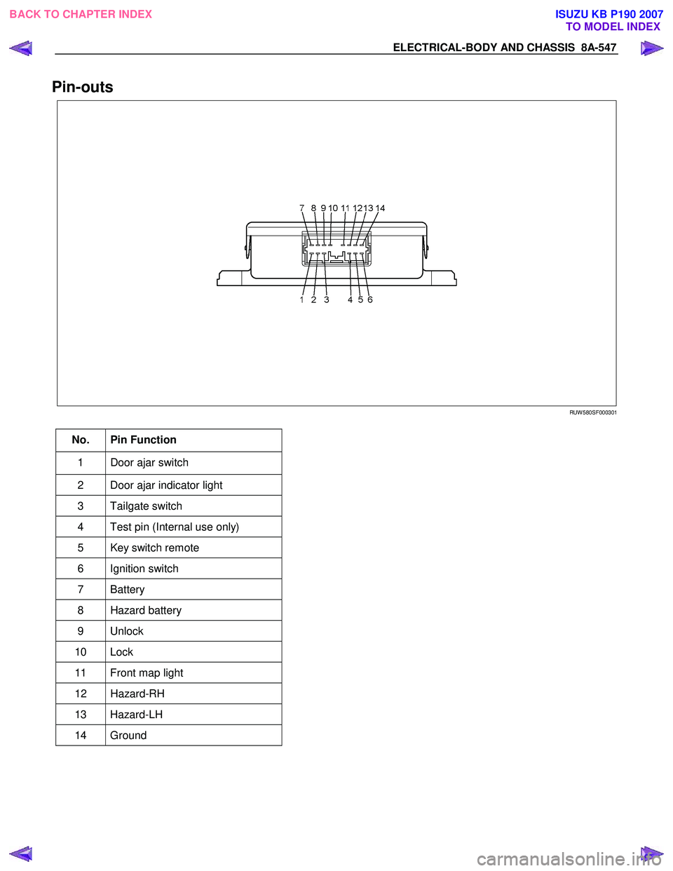
Pin-outs
RUW 580SF000301
No. Pin Function
1 Door ajar switch
2 Door ajar indicator light
3 Tailgate switch
4 Test pin (Internal use only)
5 Key switch remote
6 Ignition switch
7 Battery
8 Hazard battery
9 Unlock
10 Lock
11 Front map light
12 Hazard-RH
13 Hazard-LH
14 Ground
BACK TO CHAPTER INDEX TO MODEL INDEXISUZU KB P190 2007
Page 5515 of 6020
ELECTRICAL-BODY AND CHASSIS 8A-577
ANTI THEFT INDICATOR
Removal
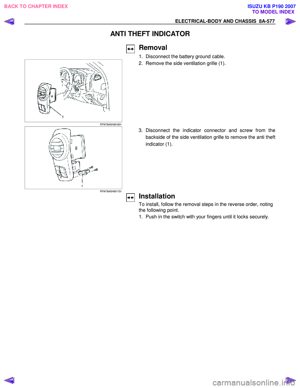
1. Disconnect the battery ground cable.
RTW 78ASH001801
2. Remove the side ventilation grille (1).
RTW 78ASH001701
3. Disconnect the indicator connector and screw from the
backside of the side ventilation grille to remove the anti theft
indicator (1).
Installation
To install, follow the removal steps in the reverse order, noting
the following point.
1. Push in the switch with your fingers until it locks securely.
BACK TO CHAPTER INDEX TO MODEL INDEXISUZU KB P190 2007
Page 5545 of 6020
ELECTRICAL-BODY AND CHASSIS 8A-607
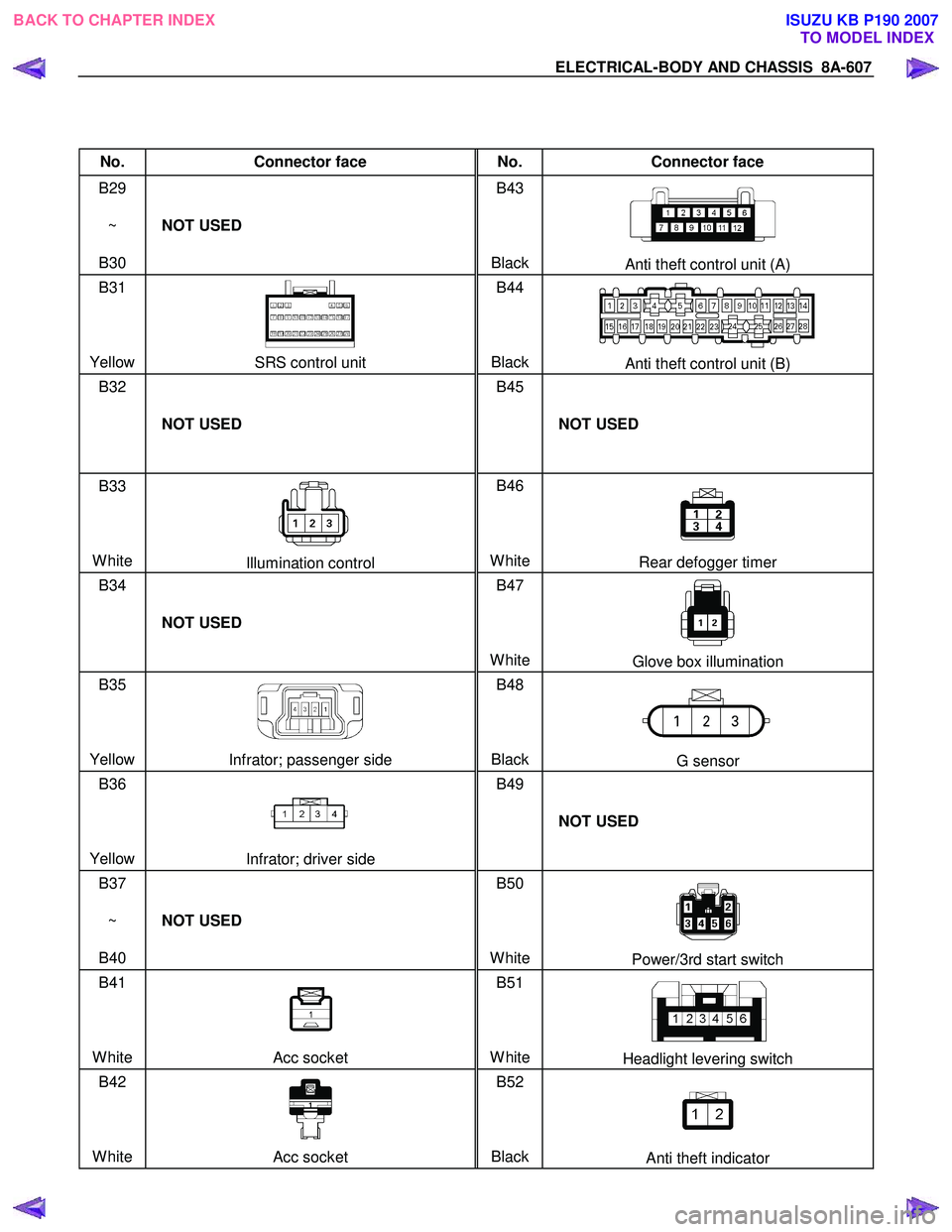
No. Connector face No. Connector face
B29
~
B30 NOT USED B43
Black
Anti theft control unit (A)
B31
Yellow
SRS control unit B44
BlackAnti theft control unit (B)
B32
NOT USED B45
NOT USED
B33
White
Illumination control B46
WhiteRear defogger timer
B34
NOT USED B47
White
Glove box illumination
B35
Yellow
Infrator; passenger side B48
BlackG sensor
B36
Yellow
Infrator; driver side B49
NOT USED
B37
~
B40 NOT USED B50
White
Power/3rd start switch
B41
White
Acc socket B51
WhiteHeadlight levering switch
B42
White
Acc socket B52
BlackAnti theft indicator
BACK TO CHAPTER INDEX TO MODEL INDEXISUZU KB P190 2007
Page 5574 of 6020
8B-2 CRUISE CONTROL SYSTEM
General Description
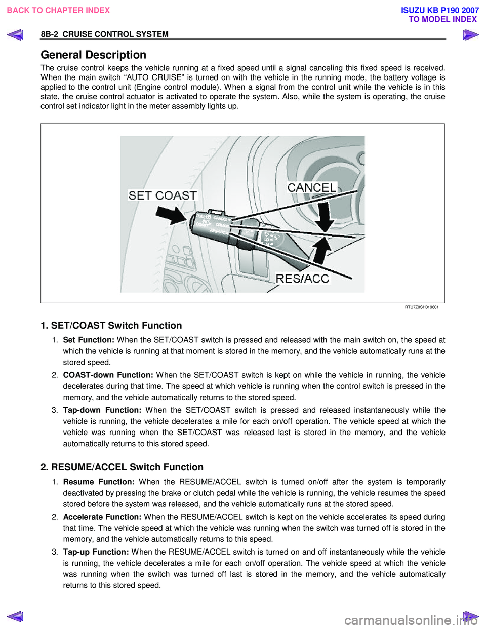
The cruise control keeps the vehicle running at a fixed speed until a signal canceling this fixed speed is received.
W hen the main switch “AUTO CRUISE” is turned on with the vehicle in the running mode, the battery voltage is
applied to the control unit (Engine control module). W hen a signal from the control unit while the vehicle is in this
state, the cruise control actuator is activated to operate the system. Also, while the system is operating, the cruise
control set indicator light in the meter assembly lights up.
RTU7Z0SH019601
1. SET/COAST Switch Function
1. Set Function: W hen the SET/COAST switch is pressed and released with the main switch on, the speed at
which the vehicle is running at that moment is stored in the memory, and the vehicle automatically runs at the
stored speed.
2. COAST-down Function: W hen the SET/COAST switch is kept on while the vehicle in running, the vehicle
decelerates during that time. The speed at which vehicle is running when the control switch is pressed in the
memory, and the vehicle automatically returns to the stored speed.
3. Tap-down Function: W hen the SET/COAST switch is pressed and released instantaneously while the
vehicle is running, the vehicle decelerates a mile for each on/off operation. The vehicle speed at which the
vehicle was running when the SET/COAST was released last is stored in the memory, and the vehicle
automatically returns to this stored speed.
2. RESUME/ACCEL Switch Function
1. Resume Function: W hen the RESUME/ACCEL switch is turned on/off after the system is temporarily
deactivated by pressing the brake or clutch pedal while the vehicle is running, the vehicle resumes the speed
stored before the system was released, and the vehicle automatically runs at the stored speed.
2. Accelerate Function: W hen the RESUME/ACCEL switch is kept on the vehicle accelerates its speed during
that time. The vehicle speed at which the vehicle was running when the switch was turned off is stored in the
memory, and the vehicle automatically returns to this speed.
3. Tap-up Function: W hen the RESUME/ACCEL switch is turned on and off instantaneously while the vehicle
is running, the vehicle decelerates a mile for each on/off operation. The vehicle speed at which the vehicle
was running when the switch was turned off last is stored in the memory, and the vehicle automatically
returns to this stored speed.
BACK TO CHAPTER INDEX TO MODEL INDEXISUZU KB P190 2007
Page 5583 of 6020
Cruise Control – HFV6 Page 8C–5
Legend
1 Engine Control Module
2 Throttle Actuator Control (TAC) Assembly
3 Cruise Control Switch Assembly
4 Instrument Cluster Assembly 5 Cruise Control ON / OFF Switch
6 Powertrain Interface Module
7 Clutch Pedal Switch Assembly (Manual Only)
8 Stop Lamp Switch Assembly
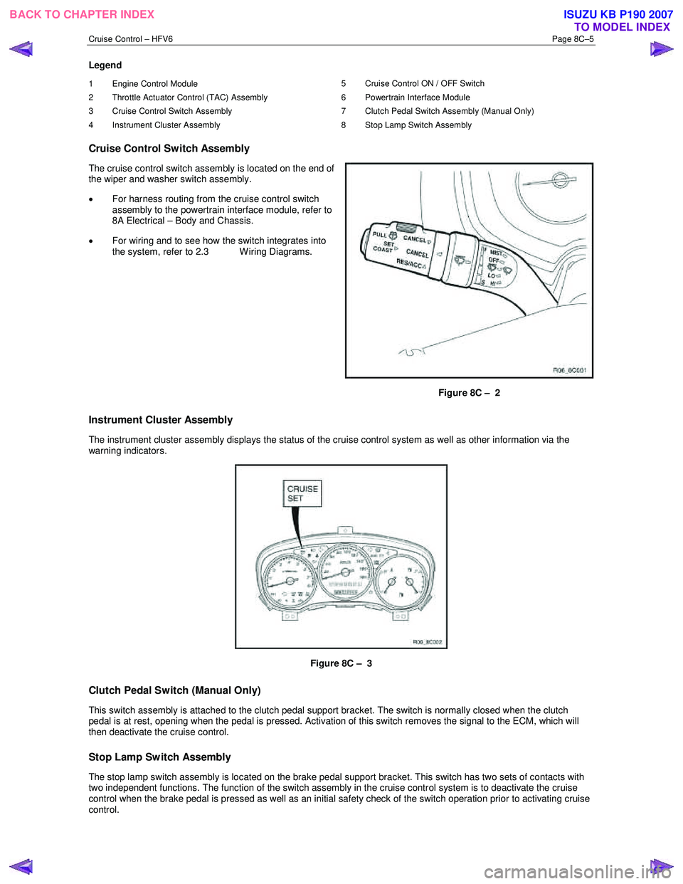
Cruise Control Switch Assembly
The cruise control switch assembly is located on the end of
the wiper and washer switch assembly.
• For harness routing from the cruise control switch
assembly to the powertrain interface module, refer to
8A Electrical – Body and Chassis.
• For wiring and to see how the switch integrates into
the system, refer to 2.3 W iring Diagrams.
Figure 8C – 2
Instrument Cluster Assembly
The instrument cluster assembly displays the status of the cruise control system as well as other information via the
warning indicators.
Figure 8C – 3
Clutch Pedal Switch (Manual Only)
This switch assembly is attached to the clutch pedal support bracket. The switch is normally closed when the clutch
pedal is at rest, opening when the pedal is pressed. Activation of this switch removes the signal to the ECM, which will
then deactivate the cruise control.
Stop Lamp Switch Assembly
The stop lamp switch assembly is located on the brake pedal support bracket. This switch has two sets of contacts with
two independent functions. The function of the switch assembly in the cruise control system is to deactivate the cruise
control when the brake pedal is pressed as well as an initial safety check of the switch operation prior to activating cruise
control.
BACK TO CHAPTER INDEX TO MODEL INDEXISUZU KB P190 2007
Page 5585 of 6020
Cruise Control – HFV6 Page 8C–7
Activated and Deactivated
When the cruise control is enabled, the vehicle speed must be above 40 km/h and the cruise control switch assembly
pressed to SET–COAST, the cruise control will be activated and the vehicle will maintain the set speed. When
deactivated by the methods described within this section, the vehicle will no longer maintain the set speed, but the cruise
control will still be engaged.
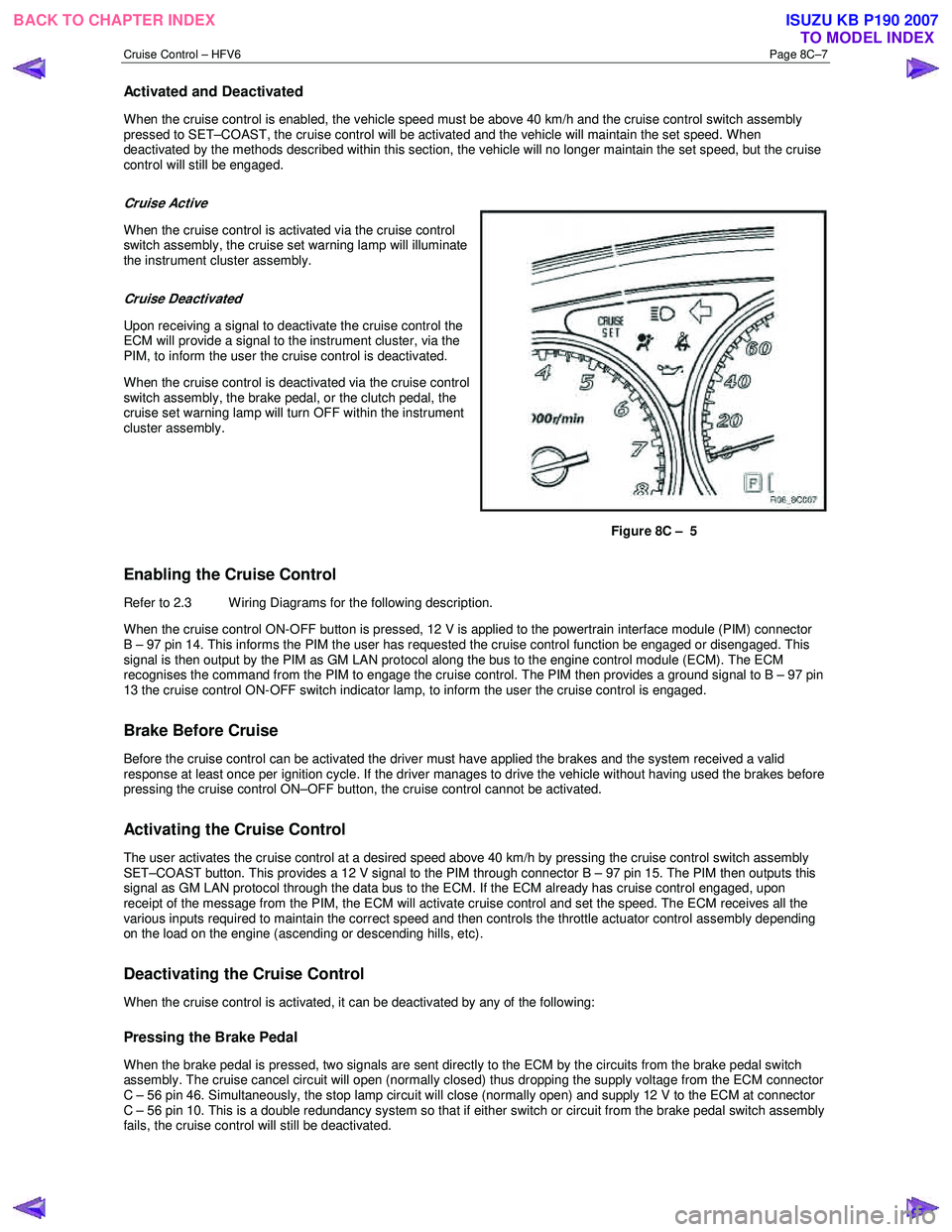
Cruise Active
When the cruise control is activated via the cruise control
switch assembly, the cruise set warning lamp will illuminate
the instrument cluster assembly.
Cruise Deactivated
Upon receiving a signal to deactivate the cruise control the
ECM will provide a signal to the instrument cluster, via the
PIM, to inform the user the cruise control is deactivated.
When the cruise control is deactivated via the cruise control
switch assembly, the brake pedal, or the clutch pedal, the
cruise set warning lamp will turn OFF within the instrument
cluster assembly.
Figure 8C – 5
Enabling the Cruise Control
Refer to 2.3 Wiring Diagrams for the following description.
W hen the cruise control ON-OFF button is pressed, 12 V is applied to the powertrain interface module (PIM) connector
B – 97 pin 14. This informs the PIM the user has requested the cruise control function be engaged or disengaged. This
signal is then output by the PIM as GM LAN protocol along the bus to the engine control module (ECM). The ECM
recognises the command from the PIM to engage the cruise control. The PIM then provides a ground signal to B – 97 pin
13 the cruise control ON-OFF switch indicator lamp, to inform the user the cruise control is engaged.
Brake Before Cruise
Before the cruise control can be activated the driver must have applied the brakes and the system received a valid
response at least once per ignition cycle. If the driver manages to drive the vehicle without having used the brakes before
pressing the cruise control ON–OFF button, the cruise control cannot be activated.
Activating the Cruise Control
The user activates the cruise control at a desired speed above 40 km/h by pressing the cruise control switch assembly
SET–COAST button. This provides a 12 V signal to the PIM through connector B – 97 pin 15. The PIM then outputs this
signal as GM LAN protocol through the data bus to the ECM. If the ECM already has cruise control engaged, upon
receipt of the message from the PIM, the ECM will activate cruise control and set the speed. The ECM receives all the
various inputs required to maintain the correct speed and then controls the throttle actuator control assembly depending
on the load on the engine (ascending or descending hills, etc).
Deactivating the Cruise Control
When the cruise control is activated, it can be deactivated by any of the following:
Pressing the Brake Pedal
When the brake pedal is pressed, two signals are sent directly to the ECM by the circuits from the brake pedal switch
assembly. The cruise cancel circuit will open (normally closed) thus dropping the supply voltage from the ECM connector
C – 56 pin 46. Simultaneously, the stop lamp circuit will close (normally open) and supply 12 V to the ECM at connector
C – 56 pin 10. This is a double redundancy system so that if either switch or circuit from the brake pedal switch assembly
fails, the cruise control will still be deactivated.
BACK TO CHAPTER INDEX TO MODEL INDEXISUZU KB P190 2007
Page 5897 of 6020
11A-46 IMMOBILIZER CONTROL SYSTEM (4JK1/4JJ1/HFV6)
The ICU is installed to the steering lock. The ICU
controls the immobilizer system by authentication of the
transponder key and the ECM. An antenna coil is a part
of the ICU and it is located around steering key lock
cylinder. An antenna coil is energized when the ICU is
performing an authentication of the transponder key.
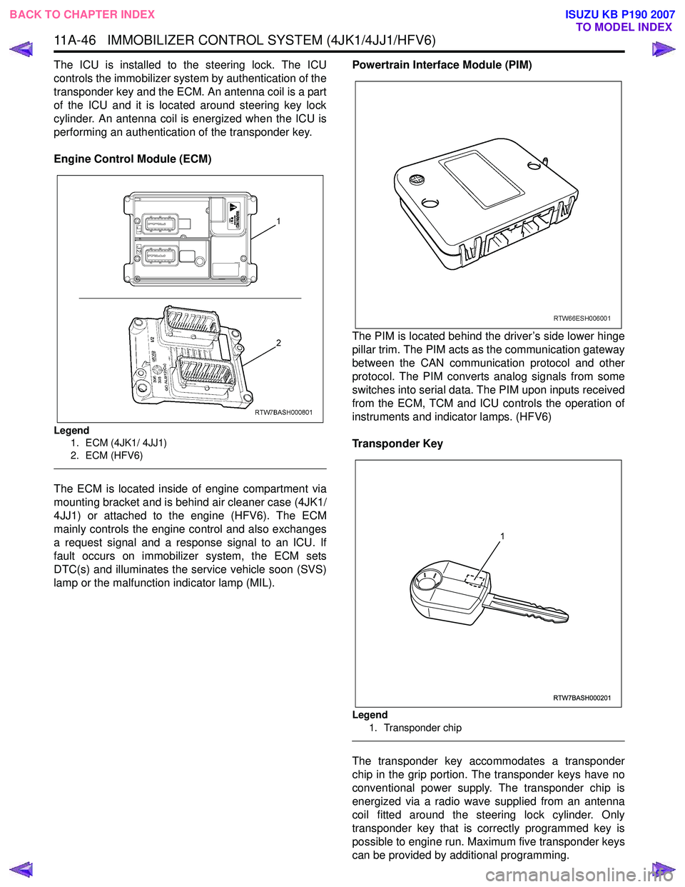
Engine Control Module (ECM)
Legend 1. ECM (4JK1/ 4JJ1)
2. ECM (HFV6)
The ECM is located inside of engine compartment via
mounting bracket and is behind air cleaner case (4JK1/
4JJ1) or attached to the engine (HFV6). The ECM
mainly controls the engine control and also exchanges
a request signal and a response signal to an ICU. If
fault occurs on immobilizer system, the ECM sets
DTC(s) and illuminates the service vehicle soon (SVS)
lamp or the malfunction indicator lamp (MIL). Powertrain Interface Module (PIM)
The PIM is located behind the driver’s side lower hinge
pillar trim. The PIM acts as the communication gateway
between the CAN communication protocol and other
protocol. The PIM converts analog signals from some
switches into serial data. The PIM upon inputs received
from the ECM, TCM and ICU controls the operation of
instruments and indicator lamps. (HFV6)
Transponder Key
Legend 1. Transponder chip
The transponder key accommodates a transponder
chip in the grip portion. The transponder keys have no
conventional power supply. The transponder chip is
energized via a radio wave supplied from an antenna
coil fitted around the steering lock cylinder. Only
transponder key that is correctly programmed key is
possible to engine run. Maximum five transponder keys
can be provided by additional programming.
RTW7BASH000201
1
BACK TO CHAPTER INDEX TO MODEL INDEX
ISUZU KB P190 2007