2007 ISUZU KB P190 indicator
[x] Cancel search: indicatorPage 4385 of 6020
TRANSMISSION CONTROL SYSTEM (JR405E) 7A2-101
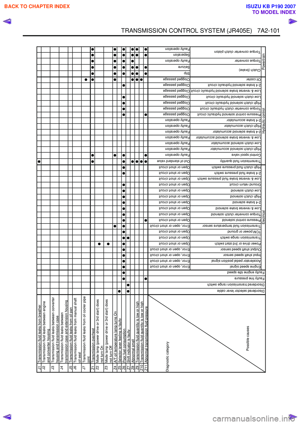
J1Transmission fluid leaks from breatherJ2
Transmission fluid leaks between engine
and converter housing
J3
Transmission fluid leaks between converter
housing and transmission case
J4
Transmission fluid leaks between
transmission case and extension housing
J5 Transmission fluid leaks from oil panJ6
Transmission fluid leaks from manual shaft
oil seal
J7
Transmission fluid leaks from oil cooler pipe
joint
Z1 Transmission overheatZ2
Mode lamp (power drive or 3rd start) does
not turn On
Z3
Mode lamp (power drive or 3rd start) does
not turn Off
Z4 A/T oil temperature lamp turns OnZ5Selector lever feeling is faultyZ6Poor fuel consumptionZ7Shift indicator is faultyZ8Abnormal smellZ9Transmission fluid quantity is low or highZ10 Transmission fluid quantity is low or highZ11Abnormal transmission fluid pressure
Error, open or short circuit
Error, open or short circuit
Error, open or short circuit
Error, open or short circuit
Open or short circuit
Open or short circuit
Open or short circuit
Error, open or short circuit
Open or short circuit
Open or short circuit
Open or short circuit
Open or short circuit
Open or short circuit
Open or short circuit
Open or short circuit
Open or short circuit
Open or short circuit
Open or short circuit
Out of standard value
Faulty operation
Faulty operation
Faulty operation
Faulty operation
Faulty operation
Faulty operation
Faulty operation
Clogged passage
Clogged passage
Clogged passage
Clogged passage
Clogged passage
Clogged passage
Clogged passage
Slip
Seizure
Faulty operation
Separation
Faulty operation
Engine speed signal
Accelerator pedal position signal
Input shaft speed sensor
Output shaft speed sensor
Power drive or 3rd start switch
Transmission range switch
TCM power or ground
Transmission fluid temperature sensor
Pressure control solenoid
Torque converter clutch solenoid
Low & reverse brake solenoid
2-4 brake solenoid
High clutch solenoid
Low clutch solenoid
Ground return circuit
Low & reverse brake fluid pressure switch
2-4 brake fluid pressure switch
High clutch fluid pressure switch
Transmission fluid quantity
Control spool valve
High clutch solenoid accumulator
Low clutch solenoid accumulator
Low & reverse brake solenoid accumulator
2-4 brake solenoid accumulator
High clutch accumulator
2-4 brake accumulator
Pressure control solenoid hydraulic circuit
Torque converter clutch hydraulic circuit
High clutch solenoid hydraulic circuit
Low clutch solenoid hydraulic circuit
Low & reverse brake solenoid hydraulic circuit
2-4 brake solenoid hydraulic circuit
Oil cooler
Torque converter
Clutch (brake)
Torque converter clutch piston
Hydraulic control
Powertrain
Diagnostic category
Possible causes
Electrical
Disordered selector lever cable
Disordered transmission range switch
Faulty line pressure
Faulty engine idle speed
BACK TO CHAPTER INDEX
TO MODEL INDEX
ISUZU KB P190 2007
Page 4404 of 6020
7A2-120 TRANSMISSION CONTROL SYSTEM (JR405E)
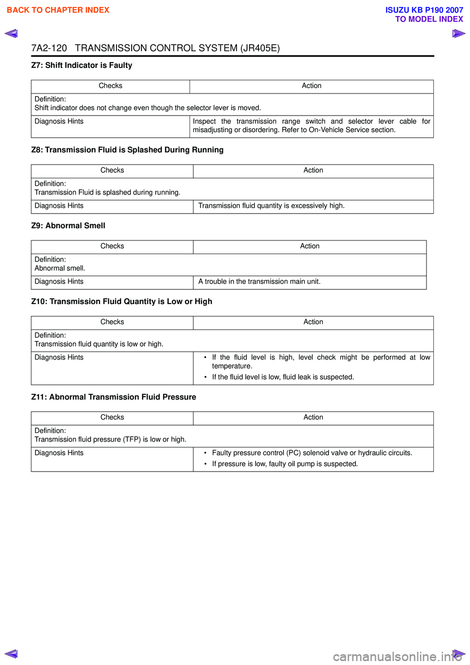
Z7: Shift Indicator is Faulty
Z8: Transmission Fluid is Splashed During Running
Z9: Abnormal Smell
Z10: Transmission Fluid Quantity is Low or High
Z11: Abnormal Transmission Fluid Pressure
Checks Action
Definition:
Shift indicator does not change even though the selector lever is moved.
Diagnosis Hints Inspect the transmission range switch and selector lever cable for
misadjusting or disordering. Refer to On-Vehicle Service section.
Checks Action
Definition:
Transmission Fluid is splashed during running.
Diagnosis Hints Transmission fluid quantity is excessively high.
Checks Action
Definition:
Abnormal smell.
Diagnosis Hints A trouble in the transmission main unit.
Checks Action
Definition:
Transmission fluid quantity is low or high.
Diagnosis Hints • If the fluid level is high, level check might be performed at low
temperature.
• If the fluid level is low, fluid leak is suspected.
Checks Action
Definition:
Transmission fluid pressure (TFP) is low or high.
Diagnosis Hints • Faulty pressure control (PC) solenoid valve or hydraulic circuits.
• If pressure is low, faulty oil pump is suspected.
BACK TO CHAPTER INDEX
TO MODEL INDEX
ISUZU KB P190 2007
Page 4464 of 6020

7A3-10 ON-VEHICLE SERVICE (JR405E)
SELECT LEVER
RTW 77ALF000201
Legend
1. Rear console
2. Front console
3. Shift lock release button
4. Shift lock button spring 5. Upper housing
6. Interlock controller
7. Base plate
8. Position indicator housing
9. Spring plate
10. Lamp assembly
11. Grooved pin
12. Shift lock unit
13. Lever assembly
14. Sleeve
15. Select lever knob
BACK TO CHAPTER INDEX
TO MODEL INDEX
ISUZU KB P190 2007
Page 4465 of 6020
ON-VEHICLE SERVICE (JR405E) 7A3-11
Remove or Disconnect
1. Block the wheels.
2. Disconnect the negative battery cable.
3. Remove the rear console and the front console.
4. Remove the 2 screws fixing the select lever knob.
5. Remove the knob together with the knob button and spring from the lever.
6. Turn the sleeve counterclockwise to remove it. Make a note of the number of turns required to free
the sleeve.
7. Remove the harness connectors from the base plate.
8. Remove the upper housing (held in place by 4 latched fasteners).
9. Remove the lamp assembly by turning it counterclockwise.
10. Remove the spring plate.
11. Remove the grooved pin.
12. Disconnect the shift cable from the select lever.
13. Remove the lever assembly by pressing the rod down (lever in N position).
14. Remove the harness connectors from the shift lock unit, then remove the shift lock unit.
15. Remove the interlock controller.
16. If the replacement of shift lock release button o
r
shift lock button spring is required, remove the
position indicator housing, the shift lock button
spring and shift lock release button can be
removed.
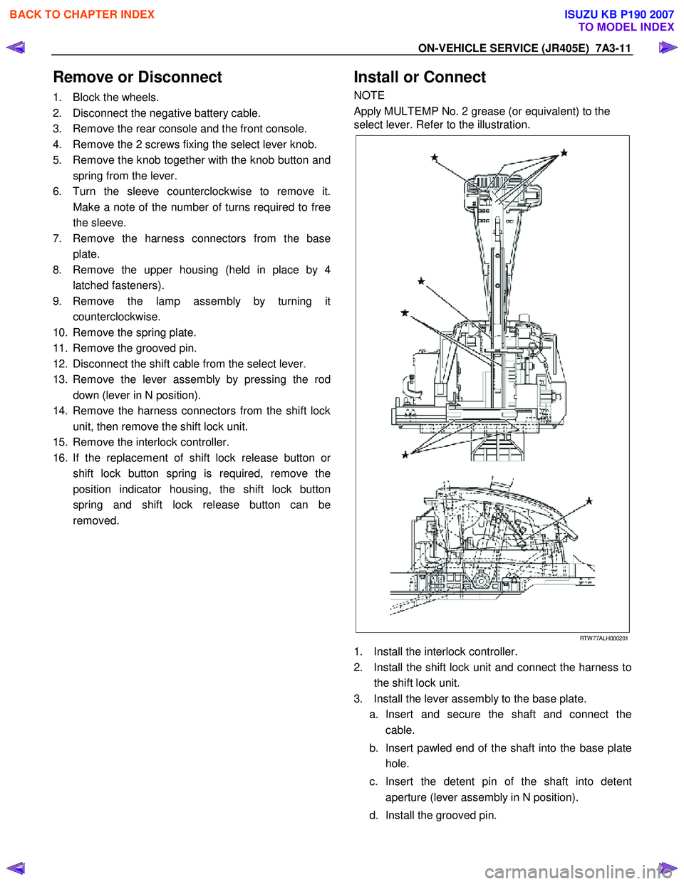
Install or Connect
NOTE
Apply MULTEMP No. 2 grease (or equivalent) to the
select lever. Refer to the illustration.
RTW 77ALH000201
1. Install the interlock controller.
2. Install the shift lock unit and connect the harness to the shift lock unit.
3. Install the lever assembly to the base plate. a. Insert and secure the shaft and connect the cable.
b. Insert pawled end of the shaft into the base plate hole.
c. Insert the detent pin of the shaft into detent aperture (lever assembly in N position).
d. Install the grooved pin.
BACK TO CHAPTER INDEX
TO MODEL INDEX
ISUZU KB P190 2007
Page 4590 of 6020
7B-26 MSG MODEL
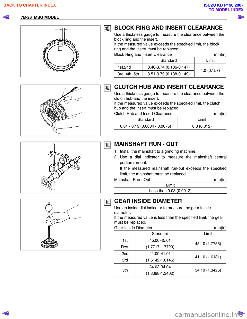
BLOCK RING AND INSERT CLEARANCE
Use a thickness gauge to measure the clearance between the
block ring and the insert.
If the measured value exceeds the specified limit, the block
ring and the insert must be replaced.
Block Ring and Insert Clearance mm(in)
StandardLimit
1st,2nd 3.46-3.74 (0.136-0.147)
3rd, 4th, 5th 3.51-3.79 (0.138-0.149)4.0 (0.157)
CLUTCH HUB AND INSERT CLEARANCE
Use a thickness gauge to measure the clearance between the
clutch hub and the insert.
If the measured value exceeds the specified limit, the clutch
hub and the insert must be replaced.
Clutch Hub and Insert Clearance mm(in)
Standard Limit
0.01 - 0.19 (0.0004 - 0.0075) 0.3 (0.012)
MAINSHAFT RUN - OUT
1. Install the mainshaft to a grinding machine.
2. Use a dial indicator to measure the mainshaft central portion run-out.
If the measured mainshaft run-out exceeds the specified limit, the mainshaft must be replaced.
Mainshaft Run - Out mm(in)
Limit
Less than 0.03 (0.0012)
GEAR INSIDE DIAMETER
Use an inside dial indicator to measure the gear inside
diameter.
If the measured value is less than the specified limit, the gear
must be replaced.
Gear Inside Diameter mm(in)
Standard Limit
1st
Rev. 45.00-45.01
(1.7717-1.7720) 45.10 (1.7756)
2nd
3rd 41.00-41.01
(1.6142-1.6146) 41.10 (1.6181)
5th34.03-34.04
(1.3398-1.3402) 34.10 (1.3425)
BACK TO CHAPTER INDEX
TO MODEL INDEX
ISUZU KB P190 2007
Page 4591 of 6020
MSG MODEL 7B-27
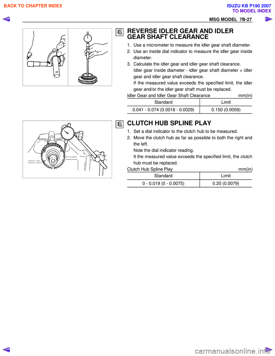
REVERSE IDLER GEAR AND IDLER
GEAR SHAFT CLEARANCE
1. Use a micrometer to measure the idler gear shaft diameter.
2. Use an inside dial indicator to measure the idler gear inside diameter.
3. Calculate the idler gear and idler gear shaft clearance.
Idler gear inside diameter - idler gear shaft diameter = idle
r
gear and idler gear shaft clearance.
If the measured value exceeds the specified limit, the idle
r
gear and/or the idler gear shaft must be replaced.
Idler Gear and Idler Gear Shaft Clearance mm(in)
Standard Limit
0.041 - 0.074 (0.0016 - 0.0029) 0.150 (0.0059)
CLUTCH HUB SPLINE PLAY
1. Set a dial indicator to the clutch hub to be measured.
2. Move the clutch hub as far as possible to both the right and the left.
Note the dial indicator reading.
It the measured value exceeds the specified limit, the clutch hub must be replaced.
Clutch Hub Spline Play mm(in
)
Standard Limit
0 - 0.019 (0 - 0.0075) 0.20 (0.0079)
BACK TO CHAPTER INDEX
TO MODEL INDEX
ISUZU KB P190 2007
Page 4592 of 6020
7B-28 MSG MODEL
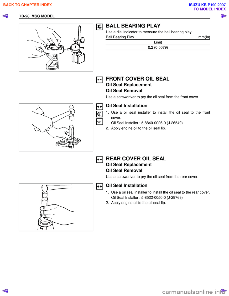
BALL BEARING PLAY
Use a dial indicator to measure the ball bearing play.
Ball Bearing Play mm(in)
Limit
0.2 (0.0079)
FRONT COVER OIL SEAL
Oil Seal Replacement
Oil Seal Removal
Use a screwdriver to pry the oil seal from the front cover.
Oil Seal Installation
1. Use a oil seal installer to install the oil seal to the front
cover.
Oil Seal Installer : 5-8840-0026-0 (J-26540)
2. Apply engine oil to the oil seal lip.
REAR COVER OIL SEAL
Oil Seal Replacement
Oil Seal Removal
Use a screwdriver to pry the oil seal from the rear cover.
Oil Seal Installation
1. Use a oil seal installer to install the oil seal to the rear cover.
Oil Seal Installer : 5-8522-0050-0 (J-29769)
2. Apply engine oil to the oil seal lip.
BACK TO CHAPTER INDEX
TO MODEL INDEX
ISUZU KB P190 2007
Page 4646 of 6020
7B1-40 MANUAL TRANSMISSION
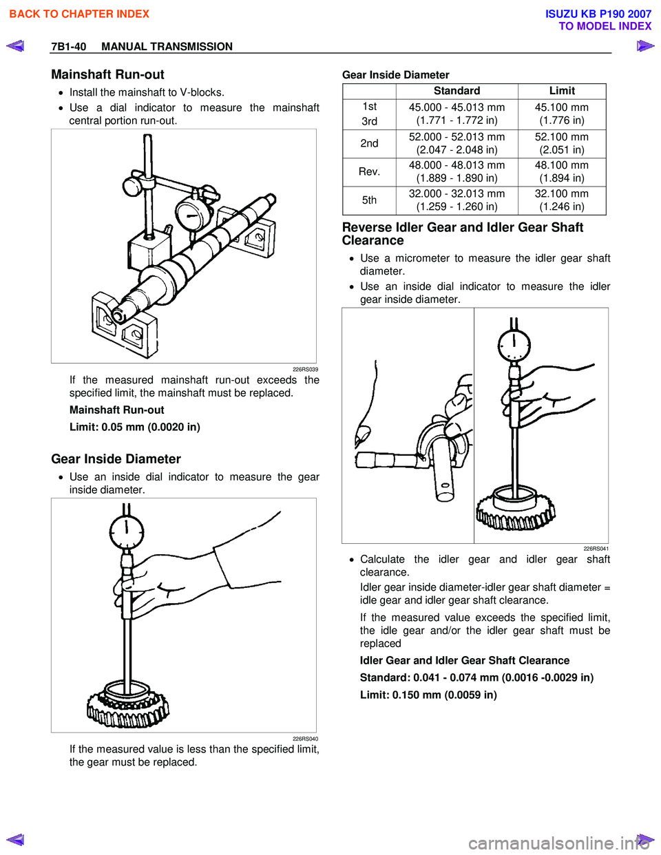
Mainshaft Run-out
• Install the mainshaft to V-blocks.
• Use a dial indicator to measure the mainshaft
central portion run-out.
226RS039
If the measured mainshaft run-out exceeds the
specified limit, the mainshaft must be replaced.
Mainshaft Run-out
Limit: 0.05 mm (0.0020 in)
Gear Inside Diameter
• Use an inside dial indicator to measure the gear
inside diameter.
226RS040
If the measured value is less than the specified limit,
the gear must be replaced.
Gear Inside Diameter
Standard Limit
1st
3rd 45.000 - 45.013 mm
(1.771 - 1.772 in) 45.100 mm
(1.776 in)
2nd 52.000 - 52.013 mm
(2.047 - 2.048 in) 52.100 mm
(2.051 in)
Rev. 48.000 - 48.013 mm
(1.889 - 1.890 in) 48.100 mm
(1.894 in)
5th 32.000 - 32.013 mm
(1.259 - 1.260 in) 32.100 mm
(1.246 in)
Reverse Idler Gear and Idler Gear Shaft
Clearance
• Use a micrometer to measure the idler gear shaft
diameter.
• Use an inside dial indicator to measure the idle
r
gear inside diameter.
226RS041
• Calculate the idler gear and idler gear shaft
clearance.
Idler gear inside diameter-idler gear shaft diameter =
idle gear and idler gear shaft clearance.
If the measured value exceeds the specified limit,
the idle gear and/or the idler gear shaft must be
replaced
Idler Gear and Idler Gear Shaft Clearance
Standard: 0.041 - 0.074 mm (0.0016 -0.0029 in)
Limit: 0.150 mm (0.0059 in)
BACK TO CHAPTER INDEX
TO MODEL INDEX
ISUZU KB P190 2007