2007 ISUZU KB P190 indicator
[x] Cancel search: indicatorPage 3284 of 6020
Engine Management – V6 – Diagnostics Page 6C1-2–6
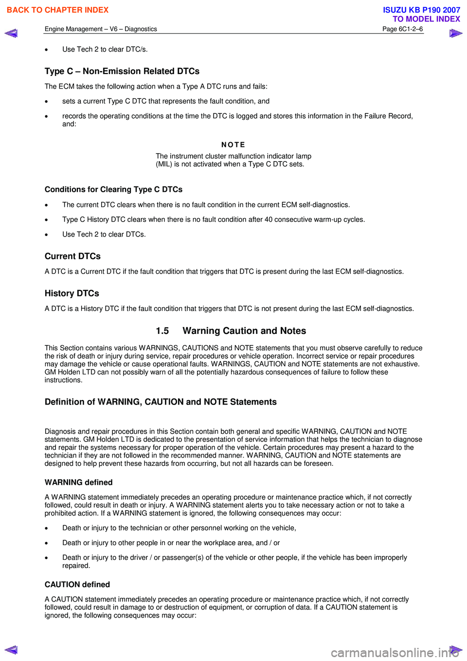
• Use Tech 2 to clear DTC/s.
Type C – Non-Emission Related DTCs
The ECM takes the following action when a Type A DTC runs and fails:
• sets a current Type C DTC that represents the fault condition, and
• records the operating conditions at the time the DTC is logged and stores this information in the Failure Record,
and:
NOTE
The instrument cluster malfunction indicator lamp
(MIL) is not activated when a Type C DTC sets.
Conditions for Clearing Type C DTCs
• The current DTC clears when there is no fault condition in the current ECM self-diagnostics.
• Type C History DTC clears when there is no fault condition after 40 consecutive warm-up cycles.
• Use Tech 2 to clear DTCs.
Current DTCs
A DTC is a Current DTC if the fault condition that triggers that DTC is present during the last ECM self-diagnostics.
History DTCs
A DTC is a History DTC if the fault condition that triggers that DTC is not present during the last ECM self-diagnostics.
1.5 Warning Caution and Notes
This Section contains various W ARNINGS, CAUTIONS and NOTE statements that you must observe carefully to reduce
the risk of death or injury during service, repair procedures or vehicle operation. Incorrect service or repair procedures
may damage the vehicle or cause operational faults. W ARNINGS, CAUTION and NOTE statements are not exhaustive.
GM Holden LTD can not possibly warn of all the potentially hazardous consequences of failure to follow these
instructions.
Definition of WARNING, CAUTION and NOTE Statements
Diagnosis and repair procedures in this Section contain both general and specific W ARNING, CAUTION and NOTE
statements. GM Holden LTD is dedicated to the presentation of service information that helps the technician to diagnose
and repair the systems necessary for proper operation of the vehicle. Certain procedures may present a hazard to the
technician if they are not followed in the recommended manner. W ARNING, CAUTION and NOTE statements are
designed to help prevent these hazards from occurring, but not all hazards can be foreseen.
WARNING defined
A W ARNING statement immediately precedes an operating procedure or maintenance practice which, if not correctly
followed, could result in death or injury. A W ARNING statement alerts you to take necessary action or not to take a
prohibited action. If a W ARNING statement is ignored, the following consequences may occur:
• Death or injury to the technician or other personnel working on the vehicle,
• Death or injury to other people in or near the workplace area, and / or
• Death or injury to the driver / or passenger(s) of the vehicle or other people, if the vehicle has been improperly
repaired.
CAUTION defined
A CAUTION statement immediately precedes an operating procedure or maintenance practice which, if not correctly
followed, could result in damage to or destruction of equipment, or corruption of data. If a CAUTION statement is
ignored, the following consequences may occur:
BACK TO CHAPTER INDEX
TO MODEL INDEX
ISUZU KB P190 2007
Page 3293 of 6020
Engine Management – V6 – Diagnostics Page 6C1-2–15
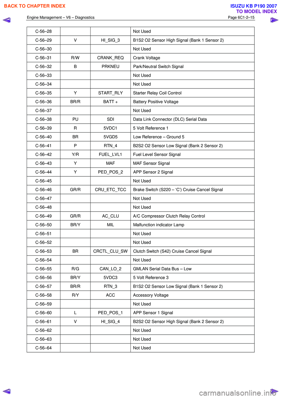
C-56–28 Not Used
C-56–29 V HI_SIG_3 B1S2 O2 Sensor High Signal (Bank 1 Sensor 2)
C-56–30 Not Used
C-56–31 R/W CRANK_REQ Crank Voltage
C-56–32 B PRKNEU Park/Neutral Switch Signal
C-56–33 Not Used
C-56–34 Not Used
C-56–35 Y START_RLY Starter Relay Coil Control
C-56–36 BR/R BATT + Battery Positive Voltage
C-56–37 Not Used
C-56–38 PU SDI Data Link Connector (DLC) Serial Data
C-56–39 R 5VDC1 5 Volt Reference 1
C-56–40 BR 5VGD5 Low Reference – Ground 5
C-56–41 P RTN_4 B2S2 O2 Sensor Low Signal (Bank 2 Sensor 2)
C-56–42 Y/R FUEL_LVL1 Fuel Level Sensor Signal
C-56–43 Y MAF MAF Sensor Signal
C-56–44 Y PED_POS_2 APP Sensor 2 Signal
C-56–45 Not Used
C-56–46 GR/R CRU_ETC_TCC Brake Switch (S220 – ‘C’) Cruise Cancel Signal
C-56–47 Not Used
C-56–48 Not Used
C-56–49 GR/R AC_CLU A/C Compressor Clutch Relay Control
C-56–50 BR/Y MIL Malfunction indicator Lamp
C-56–51 Not Used
C-56–52 Not Used
C-56–53 BR CRCTL_CLU_SW Clutch Switch (S42) Cruise Cancel Signal
C-56–54 Not Used
C-56–55 R/G CAN_LO_2 GMLAN Serial Data Bus – Low
C-56–56 BR/Y 5VDC3 5 Volt Reference 3
C-56–57 BR/R RTN_3 B1S2 O2 Sensor Low Signal (Bank 1 Sensor 2)
C-56–58 R/Y ACC Accessory Voltage
C-56–59 Not Used
C-56–60 L PED_POS_1 APP Sensor 1 Signal
C-56–61 V HI_SIG_4 B2S2 O2 Sensor High Signal (Bank 2 Sensor 2)
C-56–62 Not Used
C-56–63 Not Used
C-56–64 Not Used
BACK TO CHAPTER INDEX
TO MODEL INDEX
ISUZU KB P190 2007
Page 3301 of 6020

Engine Management – V6 – Diagnostics Page 6C1-2–23
• there is no Current DTC but a History DTC is stored.
Diagnostic Table
Checks Actions
Preliminary
• Perform the preliminary checks. Refer to 4.3 Preliminary Checks in this
Section.
• Gather information from the customer regarding the conditions that trigger the
intermittent fault such as:
• At what engine or ambient temperature range does the fault occur?
• Does the fault occur when operating aftermarket electrical equipment inside
the vehicle?
• Does the fault occur on rough roads or in wet road conditions?
• If the intermittent fault is a start and then stall condition, check the immobiliser
system. Refer to 11A Immobiliser.
Tech 2 Tests The following are lists of Tech 2 diagnostic tests that may be used to diagnose
intermittent faults:
• W riggle test the suspected wiring harness and connectors while observing Tech 2
operating parameters. If Tech 2 read-out fluctuates during this procedure, check
the tested wiring harness circuit for a loose connection.
• Observe the freeze frame / failure records for the suspected history DTC and then
operate the vehicle in the conditions that triggers the intermittent fault while an
assistant observes the suspected Tech 2 operating parameter data.
• Capture and store data in the snapshot mode when the fault occurs. The stored
data may be played back at a slower rate to aid diagnostics. Refer to Tech 2 User
Instructions for further information on the Snapshot function.
• Compare the engine operating parameters of the engine being diagnosed to the
engine operating parameters of a known good engine.
Malfunction Indicator Lamp The following conditions may cause an intermittent Malfunction Indicator Lamp fault with no DTC listed:
• Electromagnetic interference (EMI) caused by a faulty relay, ECM controlled
solenoid, switch or other external source.
• Incorrect installation of aftermarket electrical equipment such as the following:
• mobile phones,
• lights, or
• radio equipment.
• ECM grounds are loose.
BACK TO CHAPTER INDEX
TO MODEL INDEX
ISUZU KB P190 2007
Page 3334 of 6020
Engine Management – V6 – Diagnostics Page 6C1-2–56
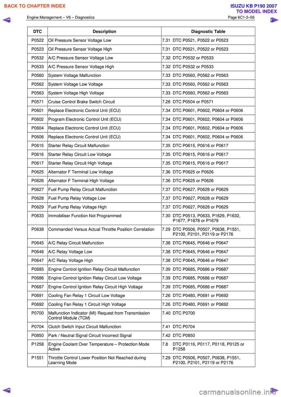
DTC Description Diagnostic Table
P0522 Oil Pressure Sensor Voltage Low 7.31 DTC P0521, P0522 or P0523
P0523 Oil Pressure Sensor Voltage High 7.31 DTC P0521, P0522 or P0523
P0532 A/C Pressure Sensor Voltage Low 7.32 DTC P0532 or P0533
P0533 A/C Pressure Sensor Voltage High 7.32 DTC P0532 or P0533
P0560 System Voltage Malfunction 7.33 DTC P0560, P0562 or P0563
P0562 System Voltage Low Voltage 7.33 DTC P0560, P0562 or P0563
P0563 System Voltage High Voltage 7.33 DTC P0560, P0562 or P0563
P0571 Cruise Control Brake Switch Circuit 7.28 DTC P0504 or P0571
P0601 Replace Electronic Control Unit (ECU) 7.34 DTC P0601, P0602, P0604 or P0606
P0602 Program Electronic Control Unit (ECU) 7.34 DTC P0601, P0602, P0604 or P0606
P0604 Replace Electronic Control Unit (ECU) 7.34 DTC P0601, P0602, P0604 or P0606
P0606 Replace Electronic Control Unit (ECU) 7.34 DTC P0601, P0602, P0604 or P0606
P0615 Starter Relay Circuit Malfunction 7.35 DTC P0615, P0616 or P0617
P0616 Starter Relay Circuit Low Voltage 7.35 DTC P0615, P0616 or P0617
P0617 Starter Relay Circuit High Voltage 7.35 DTC P0615, P0616 or P0617
P0625 Alternator F Terminal Low Voltage 7.36 DTC P0625 or P0626
P0626 Alternator F Terminal High Voltage 7.36 DTC P0625 or P0626
P0627 Fuel Pump Relay Circuit Malfunction 7.37 DTC P0627, P0628 or P0629
P0628 Fuel Pump Relay Voltage Low 7.37 DTC P0627, P0628 or P0629
P0629 Fuel Pump Relay Voltage High 7.37 DTC P0627, P0628 or P0629
P0633 Immobiliser Function Not Programmed 7.30 DTC P0513, P0633, P1629, P1632,
P1677, P1678 or P1679
P0638 Commanded Versus Actual Throttle Position Correlation 7.29 DTC P0506, P0507, P0638, P1551, P2100, P2101, P2119 or P2176
P0645 A/C Relay Circuit Malfunction 7.38 DTC P0645, P0646 or P0647
P0646 A/C Relay Voltage Low 7.38 DTC P0645, P0646 or P0647
P0647 A/C Relay Voltage High 7.38 DTC P0645, P0646 or P0647
P0685 Engine Control Ignition Relay Circuit Malfunction 7.39 DTC P0685, P0686 or P0687
P0686 Engine Control Ignition Relay Circuit Low Voltage 7.39 DTC P0685, P0686 or P0687
P0687 Engine Control Ignition Relay Circuit High Voltage 7.39 DTC P0685, P0686 or P0687
P0691 Cooling Fan Relay 1 Circuit Low Voltage 7.26 DTC P0480, P0691 or P0692
P0692 Cooling Fan Relay 1 Circuit High Voltage 7.26 DTC P0480, P0691 or P0692
P0700 Malfunction Indicator (MI) Request from Transmission
Control Module (TCM) 7.40 DTC P0700
P0704 Clutch Switch Input Circuit Malfunction
7.41 DTC P0704
P0850 Park / Neutral Signal Circuit Incorrect Signal 7.42 DTC P0850
P1258 Engine Coolant Over Temperature – Protection Mode
Active 7.8 DTC P0116, P0117, P0118, P0125 or
P1258
P1551 Throttle Control Lower Position Not Reached during Learning Mode 7.29 DTC P0506, P0507, P0638, P1551,
P2100, P2101, P2119 or P2176
BACK TO CHAPTER INDEX
TO MODEL INDEX
ISUZU KB P190 2007
Page 3366 of 6020
Engine Management – V6 – Diagnostics Page 6C1-2–88
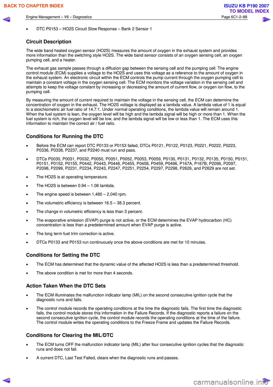
• DTC P0153 – HO2S Circuit Slow Response – Bank 2 Sensor 1
Circuit Description
The wide band heated oxygen sensor (HO2S) measures the amount of oxygen in the exhaust system and provides
more information than the switching style HO2S. The wide band sensor consists of an oxygen sensing cell, an oxygen
pumping cell, and a heater.
The exhaust gas sample passes through a diffusion gap between the sensing cell and the pumping cell. The engine
control module (ECM) supplies a voltage to the HO2S and uses this voltage as a reference to the amount of oxygen in
the exhaust system. An electronic circuit within the ECM controls the pump current through the oxygen pumping cell to
maintain a constant voltage in the oxygen sensing cell. The ECM monitors the voltage variation in the sensing cell and
attempts to keep the voltage constant by increasing or decreasing the amount of current flow, or oxygen ion flow, to the
pumping cell.
By measuring the amount of current required to maintain the voltage in the sensing cell, the ECM can determine the
concentration of oxygen in the exhaust. The HO2S voltage is displayed as a lambda value. A lambda value of 1 is equal
to a stoichiometric air fuel ratio of 14.7:1. Under normal operating conditions, the lambda value will remain around 1.
W hen the fuel system is lean, the oxygen level will be high and the lambda signal will be high or more than 1. W hen the
fuel system is rich, the oxygen level will be low, and the lambda signal will be low or less than 1. The ECM uses this
information to maintain the correct air / fuel ratio.
Conditions for Running the DTC
• Before the ECM can report DTC P0133 or P0153 failed, DTCs P0121, P0122, P0123, P0221, P0222, P0223,
P0336, P0338, P2237, and P2240 must run and pass.
• DTCs P0030, P0031, P0032, P0050, P0051, P0052, P0053, P0059, P0130, P0131, P0132, P0135, P0150, P0151,
P0151, P0152, P0155, P0442, P0443, P0446, P0455, P0458, P0459, P0496, P167A, P167B, P2096, P2097,
P2098, P2099, P2231, P2234, P2243, P2247, P2251, P2254, P2297, P2298, P2626, and P2629 are not set.
• The HO2S is at operating temperature.
• The HO2S is between 0.94 – 1.06 lambda.
• The engine speed is between 1,480 – 2,040 rpm.
• The volumetric efficiency is between 16.5 – 38.3 percent.
• The change in volumetric efficiency is less than 3 percent.
• The evaporative emission (EVAP) purge is not active, or the ECM determines the EVAP hydrocarbon (HC)
concentration is less than a predetermined amount when EVAP purge is active.
• The long term fuel trim correction is active.
• DTCs P0133 and P0153 run continuously once the above conditions are met for 10 minutes.
Conditions for Setting the DTC
• The ECM has determined that the dynamic value of the affected HO2S is less than a predetermined threshold.
• The above condition is met for more than 4 seconds.
Action Taken When the DTC Sets
• The ECM illuminates the malfunction indicator lamp (MIL) on the second consecutive ignition cycle that the
diagnostic runs and fails.
• The control module records the operating conditions at the time the diagnostic fails. The first time the diagnostic
fails, the control module stores this information in the Failure Records. If the diagnostic reports a failure on the
second consecutive ignition cycle, the control module records the operating conditions at the time of the failure.
The control module writes the operating conditions to the Freeze Frame and updates the Failure Records.
Conditions for Clearing the MIL/DTC
• The ECM turns OFF the malfunction indicator lamp (MIL) after four consecutive ignition cycles that the diagnostic
runs and does not fail.
• A current DTC, Last Test Failed, clears when the diagnostic runs and passes.
BACK TO CHAPTER INDEX
TO MODEL INDEX
ISUZU KB P190 2007
Page 3370 of 6020
Engine Management – V6 – Diagnostics Page 6C1-2–92
P0340, P0341, P0345, P0346, P0351-P0358, P0365, P0366, P0390, P0391, P0442, P0443, P0446, P0449,
P0453, P0454, P0455, P0458, P0459, and P0496 are not set.
• The ECT Sensor parameter is more than 66° C.
• The Vehicle Speed Sensor parameter is between 5 – 180 km/h.
• The calculated catalytic converter temperature is more than 520° C.
• DTC P0139 or P0159 runs continuously once the above conditions are met.
Conditions for Setting the DTC
• The ECM detects that the decel fuel cut-off and rich-to-lean transition time has exceeded 1 second.
Action Taken When the DTC Sets
• The ECM illuminates the malfunction indicator lamp (MIL) on the second consecutive ignition cycle that the
diagnostic runs and fails.
• The ECM records the operating conditions at the time the diagnostic fails. The first time the diagnostic fails, the
control module stores this information in the Failure Records. If the diagnostic reports a failure on the second
consecutive ignition cycle, the control module records the operating conditions at the time of the failure.
• The ECM writes the operating conditions to the Freeze Frame and updates the Failure Records.
Conditions for Clearing the MIL/DTC
• The ECM turns OFF the malfunction indicator lamp (MIL) after three consecutive ignition cycles that the diagnostic
runs and does not fail.
• A current DTC, Last Test Failed, clears when the diagnostic runs and passes.
• A history DTC clears after 40 consecutive warm-up cycles, if no failures are reported by this or any other emission
related diagnostic.
• Use Tech 2 to clear the MIL and the DTC.
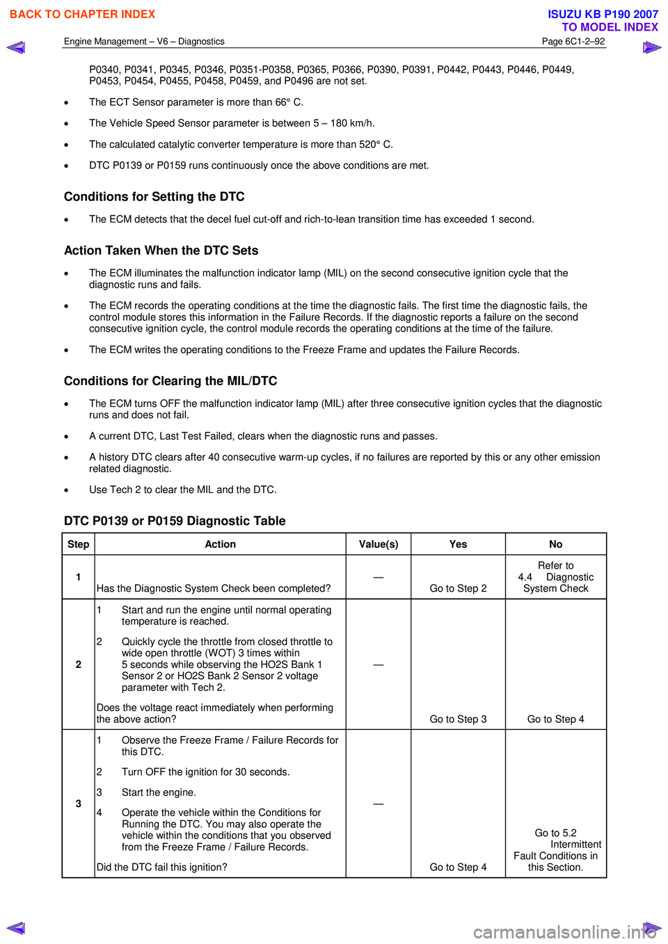
DTC P0139 or P0159 Diagnostic Table
Step Action Value(s) Yes No
1
Has the Diagnostic System Check been completed? —
Go to Step 2 Refer to
4.4 Diagnostic System Check
2 1 Start and run the engine until normal operating
temperature is reached.
2 Quickly cycle the throttle from closed throttle to wide open throttle (W OT) 3 times within
5 seconds while observing the HO2S Bank 1
Sensor 2 or HO2S Bank 2 Sensor 2 voltage
parameter with Tech 2.
Does the voltage react immediately when performing
the above action? —
Go to Step 3 Go to Step 4
3 1 Observe the Freeze Frame / Failure Records for
this DTC.
2 Turn OFF the ignition for 30 seconds.
3 Start the engine.
4 Operate the vehicle within the Conditions for Running the DTC. You may also operate the
vehicle within the conditions that you observed
from the Freeze Frame / Failure Records.
Did the DTC fail this ignition? —
Go to Step 4 Go to 5.2
Intermittent Fault Conditions in this Section.
BACK TO CHAPTER INDEX
TO MODEL INDEX
ISUZU KB P190 2007
Page 3380 of 6020
Engine Management – V6 – Diagnostics Page 6C1-2–102
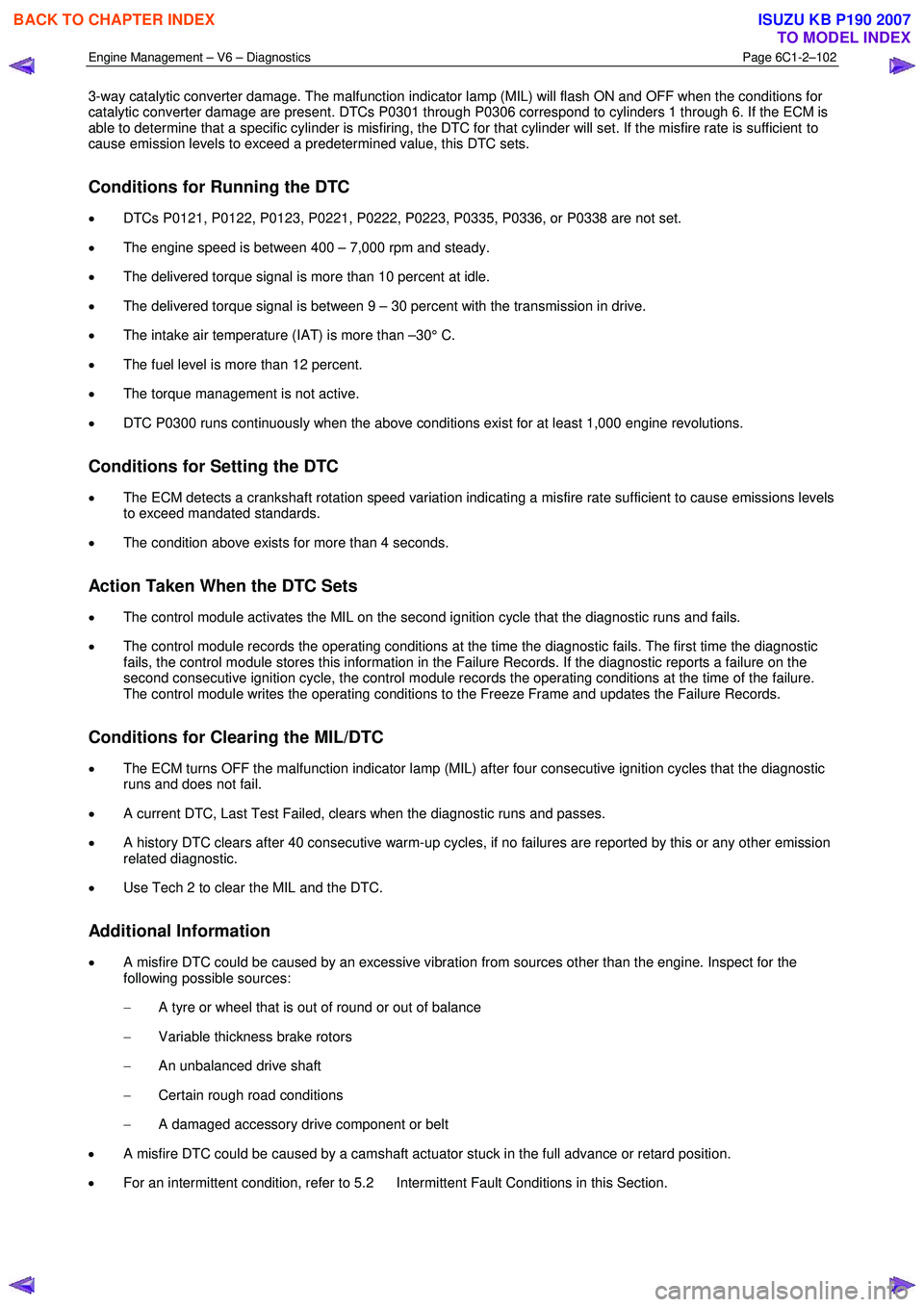
3-way catalytic converter damage. The malfunction indicator lamp (MIL) will flash ON and OFF when the conditions for
catalytic converter damage are present. DTCs P0301 through P0306 correspond to cylinders 1 through 6. If the ECM is
able to determine that a specific cylinder is misfiring, the DTC for that cylinder will set. If the misfire rate is sufficient to
cause emission levels to exceed a predetermined value, this DTC sets.
Conditions for Running the DTC
• DTCs P0121, P0122, P0123, P0221, P0222, P0223, P0335, P0336, or P0338 are not set.
• The engine speed is between 400 – 7,000 rpm and steady.
• The delivered torque signal is more than 10 percent at idle.
• The delivered torque signal is between 9 – 30 percent with the transmission in drive.
• The intake air temperature (IAT) is more than –30° C.
• The fuel level is more than 12 percent.
• The torque management is not active.
• DTC P0300 runs continuously when the above conditions exist for at least 1,000 engine revolutions.
Conditions for Setting the DTC
• The ECM detects a crankshaft rotation speed variation indicating a misfire rate sufficient to cause emissions levels
to exceed mandated standards.
• The condition above exists for more than 4 seconds.
Action Taken When the DTC Sets
• The control module activates the MIL on the second ignition cycle that the diagnostic runs and fails.
• The control module records the operating conditions at the time the diagnostic fails. The first time the diagnostic
fails, the control module stores this information in the Failure Records. If the diagnostic reports a failure on the
second consecutive ignition cycle, the control module records the operating conditions at the time of the failure.
The control module writes the operating conditions to the Freeze Frame and updates the Failure Records.
Conditions for Clearing the MIL/DTC
• The ECM turns OFF the malfunction indicator lamp (MIL) after four consecutive ignition cycles that the diagnostic
runs and does not fail.
• A current DTC, Last Test Failed, clears when the diagnostic runs and passes.
• A history DTC clears after 40 consecutive warm-up cycles, if no failures are reported by this or any other emission
related diagnostic.
• Use Tech 2 to clear the MIL and the DTC.
Additional Information
• A misfire DTC could be caused by an excessive vibration from sources other than the engine. Inspect for the
following possible sources:
− A tyre or wheel that is out of round or out of balance
− Variable thickness brake rotors
− An unbalanced drive shaft
− Certain rough road conditions
− A damaged accessory drive component or belt
• A misfire DTC could be caused by a camshaft actuator stuck in the full advance or retard position.
• For an intermittent condition, refer to 5.2 Intermittent Fault Conditions in this Section.
BACK TO CHAPTER INDEX
TO MODEL INDEX
ISUZU KB P190 2007
Page 3383 of 6020
Engine Management – V6 – Diagnostics Page 6C1-2–105
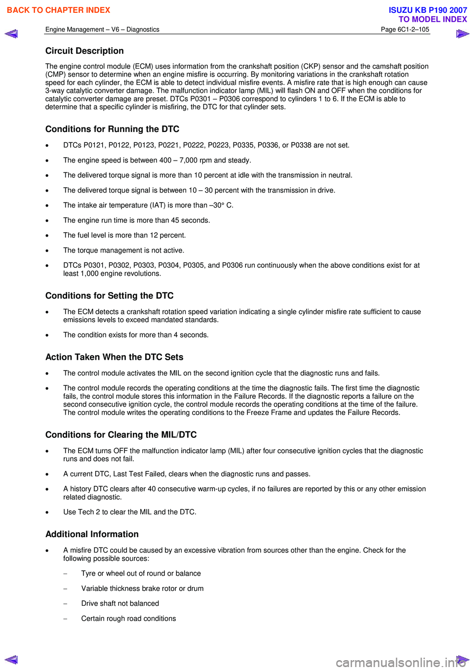
Circuit Description
The engine control module (ECM) uses information from the crankshaft position (CKP) sensor and the camshaft position
(CMP) sensor to determine when an engine misfire is occurring. By monitoring variations in the crankshaft rotation
speed for each cylinder, the ECM is able to detect individual misfire events. A misfire rate that is high enough can cause
3-way catalytic converter damage. The malfunction indicator lamp (MIL) will flash ON and OFF when the conditions for
catalytic converter damage are preset. DTCs P0301 – P0306 correspond to cylinders 1 to 6. If the ECM is able to
determine that a specific cylinder is misfiring, the DTC for that cylinder sets.
Conditions for Running the DTC
• DTCs P0121, P0122, P0123, P0221, P0222, P0223, P0335, P0336, or P0338 are not set.
• The engine speed is between 400 – 7,000 rpm and steady.
• The delivered torque signal is more than 10 percent at idle with the transmission in neutral.
• The delivered torque signal is between 10 – 30 percent with the transmission in drive.
• The intake air temperature (IAT) is more than –30° C.
• The engine run time is more than 45 seconds.
• The fuel level is more than 12 percent.
• The torque management is not active.
• DTCs P0301, P0302, P0303, P0304, P0305, and P0306 run continuously when the above conditions exist for at
least 1,000 engine revolutions.
Conditions for Setting the DTC
• The ECM detects a crankshaft rotation speed variation indicating a single cylinder misfire rate sufficient to cause
emissions levels to exceed mandated standards.
• The condition exists for more than 4 seconds.
Action Taken When the DTC Sets
• The control module activates the MIL on the second ignition cycle that the diagnostic runs and fails.
• The control module records the operating conditions at the time the diagnostic fails. The first time the diagnostic
fails, the control module stores this information in the Failure Records. If the diagnostic reports a failure on the
second consecutive ignition cycle, the control module records the operating conditions at the time of the failure.
The control module writes the operating conditions to the Freeze Frame and updates the Failure Records.
Conditions for Clearing the MIL/DTC
• The ECM turns OFF the malfunction indicator lamp (MIL) after four consecutive ignition cycles that the diagnostic
runs and does not fail.
• A current DTC, Last Test Failed, clears when the diagnostic runs and passes.
• A history DTC clears after 40 consecutive warm-up cycles, if no failures are reported by this or any other emission
related diagnostic.
• Use Tech 2 to clear the MIL and the DTC.
Additional Information
• A misfire DTC could be caused by an excessive vibration from sources other than the engine. Check for the
following possible sources:
− Tyre or wheel out of round or balance
− Variable thickness brake rotor or drum
− Drive shaft not balanced
− Certain rough road conditions
BACK TO CHAPTER INDEX
TO MODEL INDEX
ISUZU KB P190 2007