2007 ISUZU KB P190 indicator
[x] Cancel search: indicatorPage 2632 of 6020
Engine Mechanical – V6 Page 6A1–153
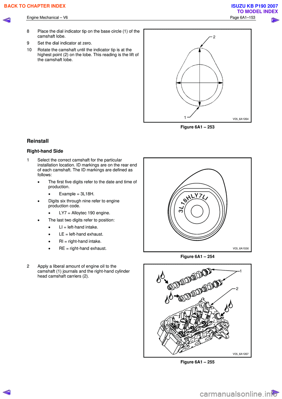
8 Place the dial indicator tip on the base circle (1) of the
camshaft lobe.
9 Set the dial indicator at zero.
10 Rotate the camshaft until the indicator tip is at the highest point (2) on the lobe. This reading is the lift of
the camshaft lobe.
Figure 6A1 – 253
Reinstall
Right-hand Side
1 Select the correct camshaft for the particular installation location. ID markings are on the rear end
of each camshaft. The ID markings are defined as
follows:
• The first five digits refer to the date and time of
production.
• Example = 3L18H.
• Digits six through nine refer to engine
production code.
• LY7 = Alloytec 190 engine.
• The last two digits refer to position:
• LI = left-hand intake.
• LE = left-hand exhaust.
• RI = right-hand intake.
• RE = right-hand exhaust.
Figure 6A1 – 254
2 Apply a liberal amount of engine oil to the camshaft (1) journals and the right-hand cylinder
head camshaft carriers (2).
Figure 6A1 – 255
BACK TO CHAPTER INDEX
TO MODEL INDEX
ISUZU KB P190 2007
Page 2648 of 6020
Engine Mechanical – V6 Page 6A1–169
Valve Guide Measurement
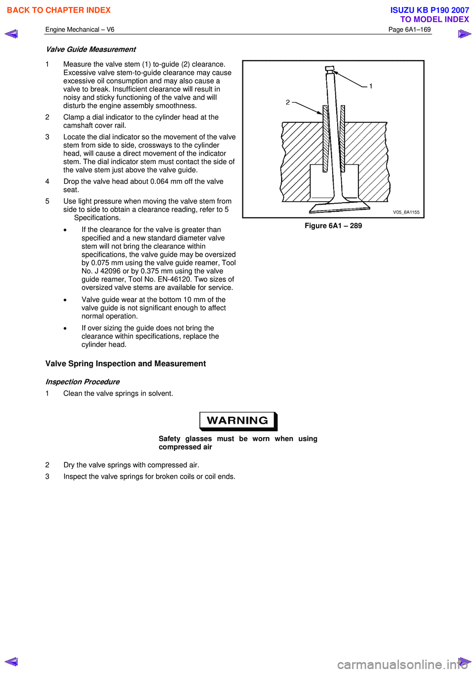
1 Measure the valve stem (1) to-guide (2) clearance.
Excessive valve stem-to-guide clearance may cause
excessive oil consumption and may also cause a
valve to break. Insufficient clearance will result in
noisy and sticky functioning of the valve and will
disturb the engine assembly smoothness.
2 Clamp a dial indicator to the cylinder head at the camshaft cover rail.
3 Locate the dial indicator so the movement of the valve stem from side to side, crossways to the cylinder
head, will cause a direct movement of the indicator
stem. The dial indicator stem must contact the side of
the valve stem just above the valve guide.
4 Drop the valve head about 0.064 mm off the valve seat.
5 Use light pressure when moving the valve stem from side to side to obtain a clearance reading, refer to 5
Specifications.
• If the clearance for the valve is greater than
specified and a new standard diameter valve
stem will not bring the clearance within
specifications, the valve guide may be oversized
by 0.075 mm using the valve guide reamer, Tool
No. J 42096 or by 0.375 mm using the valve
guide reamer, Tool No. EN-46120. Two sizes of
oversized valve stems are available for service.
• Valve guide wear at the bottom 10 mm of the
valve guide is not significant enough to affect
normal operation.
• If over sizing the guide does not bring the
clearance within specifications, replace the
cylinder head.
Figure 6A1 – 289
Valve Spring Inspection and Measurement
Inspection Procedure
1 Clean the valve springs in solvent.
Safety glasses must be worn when using
compressed air
2 Dry the valve springs with compressed air.
3 Inspect the valve springs for broken coils or coil ends.
BACK TO CHAPTER INDEX
TO MODEL INDEX
ISUZU KB P190 2007
Page 2650 of 6020
Engine Mechanical – V6 Page 6A1–171
Valve Seat Width Measurement Procedure
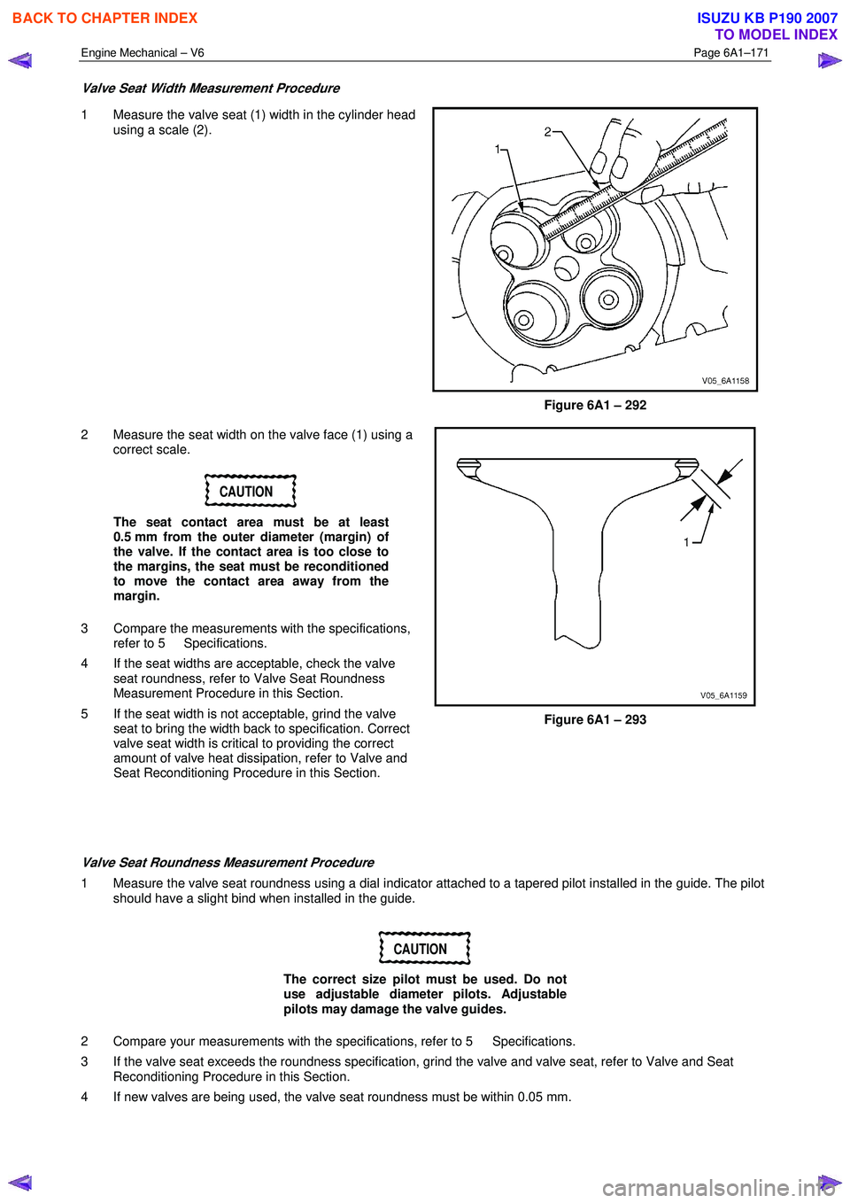
1 Measure the valve seat (1) width in the cylinder head
using a scale (2).
Figure 6A1 – 292
2 Measure the seat width on the valve face (1) using a correct scale.
CAUTION
The seat contact area must be at least
0.5 mm from the outer diameter (margin) of
the valve. If the contact area is too close to
the margins, the seat must be reconditioned
to move the contact area away from the
margin.
3 Compare the measurements with the specifications, refer to 5 Specifications.
4 If the seat widths are acceptable, check the valve seat roundness, refer to Valve Seat Roundness
Measurement Procedure in this Section.
5 If the seat width is not acceptable, grind the valve seat to bring the width back to specification. Correct
valve seat width is critical to providing the correct
amount of valve heat dissipation, refer to Valve and
Seat Reconditioning Procedure in this Section.
Figure 6A1 – 293
Valve Seat Roundness Measurement Procedure
1 Measure the valve seat roundness using a dial indicator attached to a tapered pilot installed in the guide. The pilot should have a slight bind when installed in the guide.
CAUTION
The correct size pilot must be used. Do not
use adjustable diameter pilots. Adjustable
pilots may damage the valve guides.
2 Compare your measurements with the specifications, refer to 5 Specifications.
3 If the valve seat exceeds the roundness specification, grind the valve and valve seat, refer to Valve and Seat Reconditioning Procedure in this Section.
4 If new valves are being used, the valve seat roundness must be within 0.05 mm.
BACK TO CHAPTER INDEX
TO MODEL INDEX
ISUZU KB P190 2007
Page 2669 of 6020

Engine Mechanical – V6 Page 6A1–190
35 Disconnect the harness connector from the transmission, refer to 7B1 Manual Transmission – V6 or 7C1, 2, 3 or 4
for automatic transmission.
36 Remove the left-hand side exhaust manifold upper heat shield (1), (Automatic transmission only).
Figure 6A1 – 330
37 Progressively loosen the seven exhaust manifold attaching bolts (2), working from the outside to the
centre and then remove the bolts.
38 Manoeuvre the exhaust manifold (3), away from the cylinder head.
39 Remove and discard the exhaust manifold to cylinder head gasket.
Figure 6A1 – 331
40 Remove the engine oil level indicator assembly (1), (automatic transmission only).
41 Remove the left-hand side exhaust manifold, (automatic transmission only).
BACK TO CHAPTER INDEX
TO MODEL INDEX
ISUZU KB P190 2007
Page 2677 of 6020
Engine Mechanical – V6 Page 6A1–198
k Timing chains, tensioners, shoes, guides & sprockets, refer to 3.16 Timing Chains, Tensioners, Shoes and
Guides.
l Cylinder head assemblies, refer to 3.22 Cylinder Head Assembly.
m Oil pan assembly, refer to 4.2 Oil Pan and Oil Pump Suction Pipe Assembly.
n Piston and connecting rod assemblies, refer to 4.5 Pistons, Pins, Rings, Connecting Rods and Big-end Bearings.
o Crankshaft assembly, refer to 4.6 Crankshaft and Main Bearings.
p Piston oil nozzles, refer 4.5 Pistons, Pins, Rings, Connecting Rods and Big-end Bearings.
Reassemble
Reassembly of the engine assembly is the reverse of the disassembly procedure.
Reinstall
Reinstallation of the engine assembly is the reverse to the removal procedure, noting the following:
NOTE
Refer to 6 Torque Wrench Specifications
for the correct torque specifications.
1 Tighten the fasteners to the correct torque specification.
Engine ground connector bolt
torque specification ............................................10.0 Nm
Power steering high pressure line
attaching bolt torque specification .............8.0 – 12.0 Nm
Power steering high pressure line
flare nut torque specification ...................25.0 – 35.0 Nm
Engine mount to frame attaching bolt
torque specification .................................44.0 – 60.0 Nm
Knock Sensor Attaching Nut
torque specification ............................................23.0 Nm
2 Use only the specified engine lubricant type and quantity. It is recommended that a fluorescent oil dye, such as that contained in J 28481-B, be added to assist in any future oil leak diagnosis.
3 Fill the cooling system with the correct quantity and grade of coolant, refer to 6B1 Engine Cooling – V6.
4 Check transmission fluid level, replenishing as required, using the specified lubricant for the transmission fitted, refer to 7C1 Automatic – 4L60E – General Information.
5 Disable the ignition system, refer to 6C1-3 Engine Management – V6 – Service Operations.
6 Crank the engine several times. Listen for any unusual noises or evidence that parts are binding.
7 Enable the ignition system. Start the engine and listen for any unusual noises.
8 Check the vehicle oil pressure gauge or warning indicator and confirm the engine has acceptable oil pressure. If required, install an oil pressure gauge and measure the engine oil pressure, refer to 2.19 Engine Oil Pressure
Diagnosis.
9 Run the engine at about 1,000 r.p.m. until the engine has reached normal operating temperature.
10 Listen for any unusual noises.
11 Check for oil, fuel, coolant and exhaust leaks while the engine is running, correcting as required.
12 Perform a final inspection for correct engine oil and coolant levels.
4.2 Oil Pan and Oil Pump Suction Pipe Assembly
Remove
1 Remove the engine assembly from the vehicle, refer to 4.1 Engine .
2 Separate the engine and transmission assemblies, refer to 7C1 Automatic – 4L60E – General Information.
3 Mount the engine assembly on a suitable engine stand.
4 Remove the engine front cover, refer to 3.15 Front Cover Assembly.
BACK TO CHAPTER INDEX
TO MODEL INDEX
ISUZU KB P190 2007
Page 2702 of 6020
Engine Mechanical – V6 Page 6A1–223
NOTE
During and after installation, ensure each piston
is positioned correctly in the correct cylinder. The
locating arrow on the top of each piston must be
pointing toward the front of the engine.
6 Repeat these procedures for the remaining piston/connecting rod assemblies.
7 Reinstall the oil pan and oil pump pick up assembly, refer to 4.2 Oil Pan and Oil Pump Suction Pipe Assembly.
8 Reinstall the cylinder heads, refer to 3.22 Cylinder Head Assembly.
9 Reinstall the engine assembly, refer to 4.1 Engine .
4.6 Crankshaft and Main Bearings
1 Remove the engine assembly, refer to 4.1 Engine .
2 Remove both cylinder head assemblies, refer to 3.22 Cylinder Head Assembly.
3 Remove the oil pan assembly, refer to 4.2 Oil Pan and Oil Pump Suction Pipe Assembly.
4 Remove the piston and connecting rod assemblies, refer to 4.5 Pistons, Pins, Rings, Connecting Rods and Big- end Bearings.
5 Remove the oil pump assembly, refer to 3.17 Oil Pump Assembly.
6 Remove the crankshaft rear oil seal and plate assembly, refer to 4.4 Crankshaft Rear Seal and Plate Assembly.
7 Remove the crankshaft position sensor, refer to 6C1-3 Engine Management – V6 – Service Operations.
Crankshaft End Play Measurement
1 Place a dial indicator at the end of the crankshaft nose.
2 Gently force the crankshaft towards the front and rear of the cylinder block with a lever while monitoring the movement of the dial indicator.
3 The crankshaft endplay should not exceed specifications, refer to 5 Specifications.
4 If the specifications are exceeded, inspect the thrust bearing thrust outer diameter and the crankshaft thrust wall for wear and/or excessive runout. Compare the values with the specifications, refer to 5 Specifications.
5 Replace the thrust bearing or crankshaft as required.
Remove
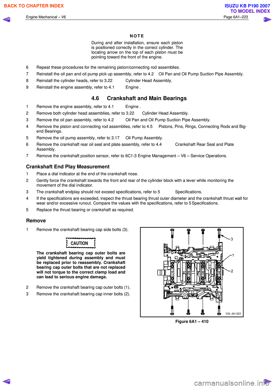
1 Remove the crankshaft bearing cap side bolts (3).
CAUTION
The crankshaft bearing cap outer bolts are
yield tightened during assembly and must
be replaced prior to reassembly. Crankshaft
bearing cap outer bolts that are not replaced
will not torque to the correct clamp load and
can lead to serious engine damage.
2 Remove the crankshaft bearing cap outer bolts (1).
3 Remove the crankshaft bearing cap inner bolts (2).
Figure 6A1 – 410
BACK TO CHAPTER INDEX
TO MODEL INDEX
ISUZU KB P190 2007
Page 2707 of 6020
Engine Mechanical – V6 Page 6A1–228
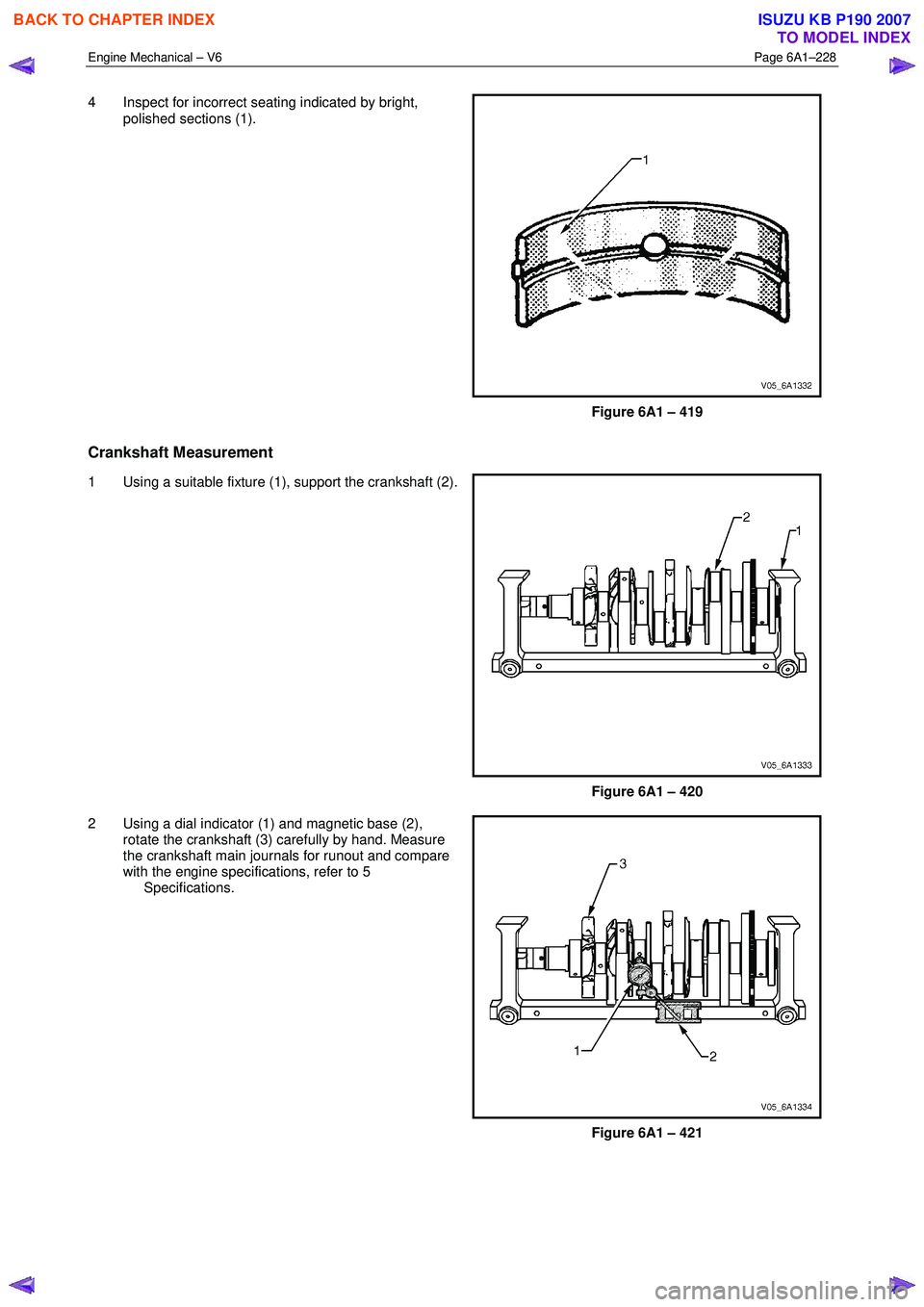
4 Inspect for incorrect seating indicated by bright,
polished sections (1).
Figure 6A1 – 419
Crankshaft Measurement
1 Using a suitable fixture (1), support the crankshaft (2).
Figure 6A1 – 420
2 Using a dial indicator (1) and magnetic base (2), rotate the crankshaft (3) carefully by hand. Measure
the crankshaft main journals for runout and compare
with the engine specifications, refer to 5
Specifications.
Figure 6A1 – 421
BACK TO CHAPTER INDEX
TO MODEL INDEX
ISUZU KB P190 2007
Page 2708 of 6020
Engine Mechanical – V6 Page 6A1–229
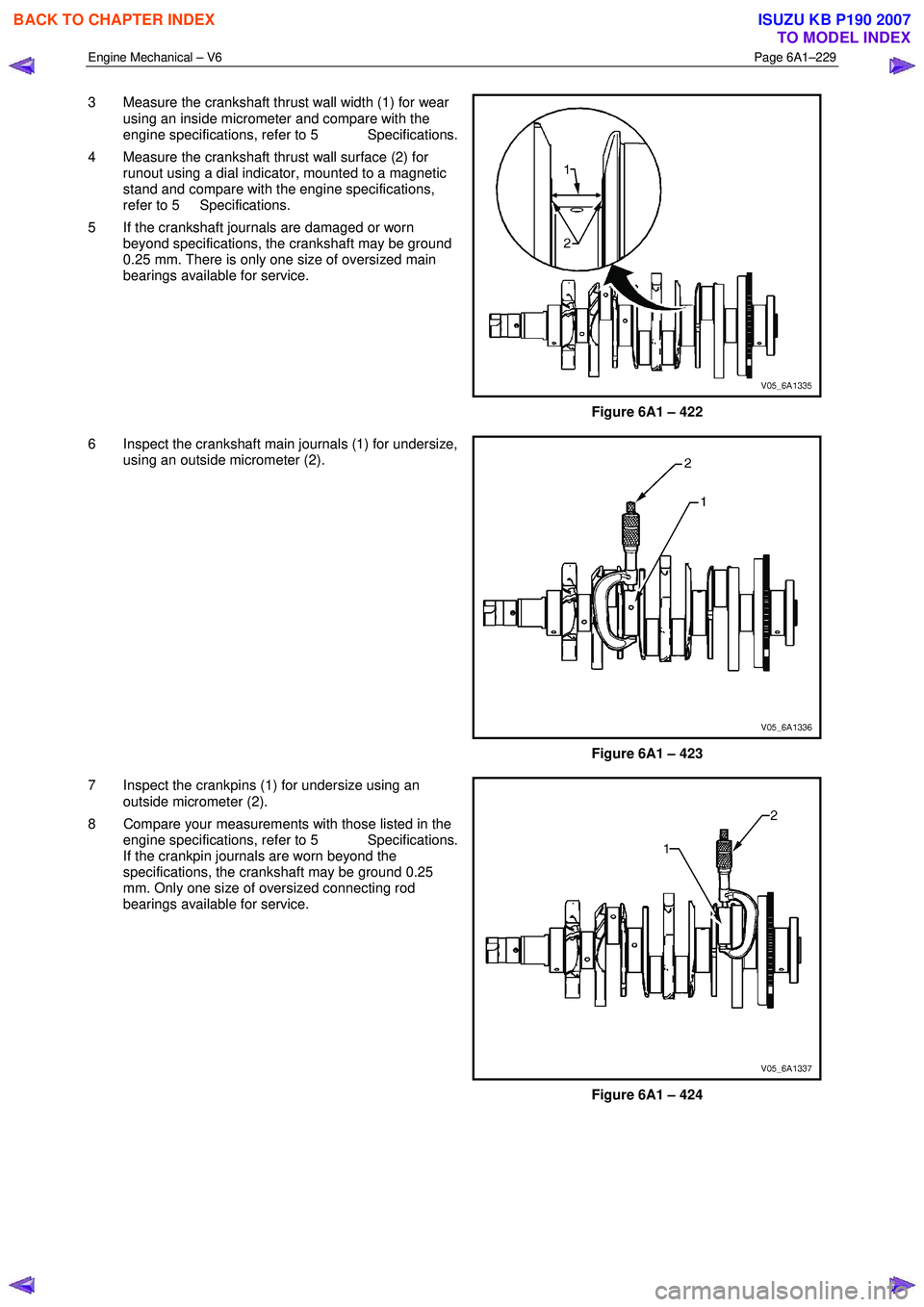
3 Measure the crankshaft thrust wall width (1) for wear
using an inside micrometer and compare with the
engine specifications, refer to 5 Specifications.
4 Measure the crankshaft thrust wall surface (2) for runout using a dial indicator, mounted to a magnetic
stand and compare with the engine specifications,
refer to 5 Specifications.
5 If the crankshaft journals are damaged or worn beyond specifications, the crankshaft may be ground
0.25 mm. There is only one size of oversized main
bearings available for service.
Figure 6A1 – 422
6 Inspect the crankshaft main journals (1) for undersize, using an outside micrometer (2).
Figure 6A1 – 423
7 Inspect the crankpins (1) for undersize using an outside micrometer (2).
8 Compare your measurements with those listed in the engine specifications, refer to 5 Specifications.
If the crankpin journals are worn beyond the
specifications, the crankshaft may be ground 0.25
mm. Only one size of oversized connecting rod
bearings available for service.
Figure 6A1 – 424
BACK TO CHAPTER INDEX
TO MODEL INDEX
ISUZU KB P190 2007