2007 ISUZU KB P190 indicator
[x] Cancel search: indicatorPage 1972 of 6020
ENGINE CONTROL SYSTEM (4JK1/4JJ1) 6E-355
Electrostatic Discharge Damage
Electronic components used in the ECM are often
designed to carry very low voltage. Electronic
components are susceptible to damage caused by
electrostatic discharge. By comparison, as much as
4,000 volts may be needed for a person to feel even
the zap of a static discharge. There are several ways
for a person to become statically charged. The most
common methods of charging are by friction and
induction.
• An example of charging by friction is a person sliding across a vehicle seat.
Important: To prevent possible electrostatic discharge
damage, follow these guidelines:
• Do not touch the ECM connector pins or soldered components on the ECM circuit board.
• Do not open the replacement part package until the part is ready to be installed.
• Before removing the part from the package, ground the package to a known good ground on
the vehicle.
• If the part has been handled while sliding across the seat, while sitting down from a standing
position, or while walking a distance, touch a
known good ground before installing the part.
• Charge by induction occurs when a person with well insulated shoes stands near a highly charged
object and momentarily touches ground. Charges
of the same polarity are drained off leaving the
person highly charged with opposite polarity.
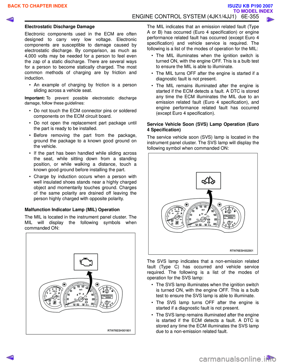
Malfunction Indicator Lamp (MIL) Operation
The MIL is located in the instrument panel cluster. The
MIL will display the following symbols when
commanded ON: The MIL indicates that an emission related fault (Type
A or B) has occurred (Euro 4 specification) or engine
performance related fault has occurred (except Euro 4
specification) and vehicle service is required. The
following is a list of the modes of operation for the MIL:
• The MIL illuminates when the ignition switch is turned ON, with the engine OFF. This is a bulb test
to ensure the MIL is able to illuminate.
• The MIL turns OFF after the engine is started if a diagnostic fault is not present.
• The MIL remains illuminated after the engine is started if the ECM detects a fault. A DTC is stored
any time the ECM illuminates the MIL due to an
emission related fault (Euro 4 specification), and
engine performance related fault has occurred
(except Euro 4 specification).
Service Vehicle Soon (SVS) Lamp Operation (Euro
4 Specification)
The service vehicle soon (SVS) lamp is located in the
instrument panel cluster. The SVS lamp will display the
following symbol when commanded ON:
The SVS lamp indicates that a non-emission related
fault (Type C) has occurred and vehicle service
required. The following is a list of the modes of
operation for the SVS lamp:
• The SVS lamp illuminates when the ignition switch is turned ON, with the engine OFF. This is a bulb
test to ensure the SVS lamp is able to illuminate.
• The SVS lamp turns OFF after the engine is started if a diagnostic fault is not present.
• The SVS lamp remains illuminated after the engine is started if the ECM detects a fault. A DTC is
stored any time the ECM illuminates the SVS lamp
due to a non-emission related fault.
RTW76ESH001901
RTW76ESH002901
BACK TO CHAPTER INDEX
TO MODEL INDEX
ISUZU KB P190 2007
Page 2001 of 6020
ENGINE DIAGNOSIS (C24SE) 6-1
SECTION 6
ENGINE DIAGNOSIS
TABLE OF CONTENTS
PAGE
Engine Diagnosis .............................................................................................................. 6- 2
Hard Starting ................................................................................................................. 6- 2
Engine Compression Test Procedure ......................................................................... 6- 3
Rough Engine Idling or Engine Stalling...................................................................... 6- 4
Rough Engine Running ................................................................................................ 6- 5
Hesitation ..................................................................................................................... . 6- 6
Engine Lacks Power ..................................................................................................... 6- 7
Engine Noisy ................................................................................................................. 6 - 8
Abnormal Noise Due to Hydraulic Lash Adjustor ...................................................... 6- 9
Troubleshooting Procedure ......................................................................................... 6- 9
Abnormal Combustion ................................................................................................. 6-11
Engine Oil Consumption Excessive............................................................................ 6-12
Fuel Consumption Excessive ...................................................................................... 6-13
Oil Problems.................................................................................................................. 6-13
Engine Oil Pressure Check .......................................................................................... 6-13
Malfunction Indicator Lamp ......................................................................................... 6-14
BACK TO CHAPTER INDEX
TO MODEL INDEX
ISUZU KB P190 2007
Page 2014 of 6020
6-14 ENGINE DIAGNOSIS (C24SE)
Malfunction Indicator Lamp
The instrument panel "CHECK ENGINE" Malfunction
Indicator lamp (MIL) illuminates by self diagnostic
system when the system checks the starting of
engine, or senses malfunctions.
Condition Possible cause Correction
"CHECK ENGINE" MIL does not
illuminate at the starting of engine Bulb defective Replace
MIL circuit open Correct or replace
Command signal circuit to operate
self diagnostic system shorted Correct or replace
Engine Control Module (ECM)
cable loosely connected,
disconnected or defective Correct or replace
ECM
defective Replace
“CHECK ENGINE” MIL
illuminates, and stays on Deterioration heated oxygen
sensor of internal element Replace
Heated oxygen sensor connector
terminal improper contact
(If applicable) Reconnect properly
Heated oxygen sensor lead wire
shorted (If applicable) Correct
Heated oxygen sensor circuit
open (If applicable) Correct or replace
Deterioration engine coolant
temperature sensor of internal
element Replace
Engine coolant temperature
sensor connector terminal
improper contact Reconnect properly
Engine coolant temperature
sensor lead wire shorted Correct
Engine coolant temperature
sensor circuit open Correct or replace
Throttle position sensor open or
shorted circuits Correct or replace
Deterioration of crankshaft
position sensor Replace
Crankshaft position sensor circuit
open or shorted Correct or replace
Vehicle speed sensor circuit open Correct or replace
Manifold absolute pressure sensor
circuit open or shorted Correct or replace
Intake air temperature sensor
circuit open or shorted Correct or replace
Fuel injector circuit open or shorted Correct or replace
ECM driver transistor defective Replace EPROM or ECM
Malfunctioning of ECM RAM
(Random Access Memory) or
Malfunctioning of ECM PROM
(Programmed Read Only Memory) Replace EPROM or ECM
BACK TO CHAPTER INDEX
TO MODEL INDEX
ISUZU KB P190 2007
Page 2154 of 6020
6D3-6 STARTING AND CHARGING SYSTEM
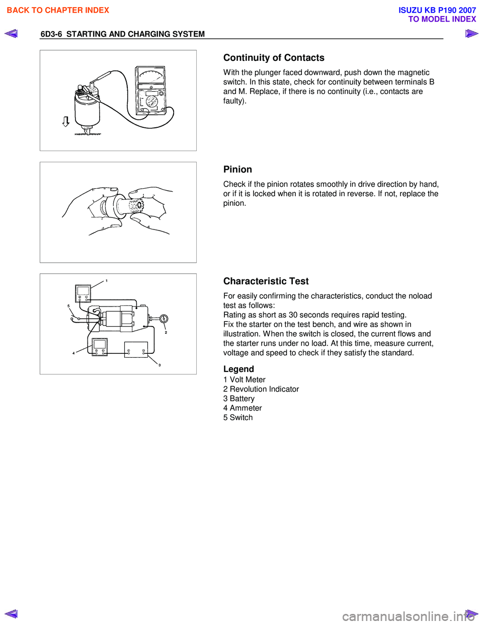
Continuity of Contacts
W ith the plunger faced downward, push down the magnetic
switch. In this state, check for continuity between terminals B
and M. Replace, if there is no continuity (i.e., contacts are
faulty).
Pinion
Check if the pinion rotates smoothly in drive direction by hand,
or if it is locked when it is rotated in reverse. If not, replace the
pinion.
Characteristic Test
For easily confirming the characteristics, conduct the noload
test as follows:
Rating as short as 30 seconds requires rapid testing.
Fix the starter on the test bench, and wire as shown in
illustration. W hen the switch is closed, the current flows and
the starter runs under no load. At this time, measure current,
voltage and speed to check if they satisfy the standard.
Legend
1 Volt Meter
2 Revolution Indicator
3 Battery
4 Ammeter
5 Switch
BACK TO CHAPTER INDEX
TO MODEL INDEX
ISUZU KB P190 2007
Page 2167 of 6020
STARTING AND CHARGING SYSTEM 6D3-19
Inspection
Generator
Before any in field testing can be undertaken it is important
that the battery's conditions is established and the terminals
are clean and tight.
Check the condition of the generator drive belt and ensure that
it is adjusted in accordance with the engine manufacturer's
recommnedations.
Battery conditions:
Note: This assessment may be difficult with maintenance free
assemblies.
Test the specific gravity of the individual cells the readings
should be within 10 points of each other, it is recommended
that the average SG should be 1.260 or higher.
A load test should be carried out to determine the ability of the
battery to supply and accept current. This is a good indicator
as to the general condition of the battery.
A load equal to the normal starting current should be placed
across the battery, the duration of this load test should not
exceed 10 seconds, during this time the terminal voltage
across the battery should not drop below 9.6 volts. Observe
each cell for signs of excessive gas liberation, usuall an
indication of cell failure.
If the battery test is clear proceed with the Generator tests as
follows.
Care should be taken when making the following connections.
It is recommended that the battery negative terminal be
disconnected before the test meters are connected, and
reconnecting the negative terminal when the meters are
inserted into the circuit under test. The warning lamp in the D+
circuit should not exceed 2 watts.
Regulating voltage test on the vehicle.
Connect a voltmeter to the generator, the positive lead to the
B+ terminal and the nagative lead to the generator casing.
Select the voltage range to suit the system, i.e. 20v for 12 volt
sysytems or 40v for 24 volt systems. Connect an ammeter in
series with the main output cable from the B+ terminal on the
generator, the range selected must be capable of reading the
maximum output from the generator.
Note the voltmeter reading before starting the engine. This
reading should increase when the engine is running indicating
generator output, start the engine and increase the engine
speed until the generator is running at 4000 rpm, switch on
vehicle loads of 5-10 A is indcated on the ammeter, the
voltmeter shoud read 14.0-14.2 v for a 12 volt system, for a 24
volt system the readings should be 5-10 A and 27.7-28.5 volts.
BACK TO CHAPTER INDEX
TO MODEL INDEX
ISUZU KB P190 2007
Page 2174 of 6020
6E–4 ENGINE DRIVEABILITY AND EMISSIONS
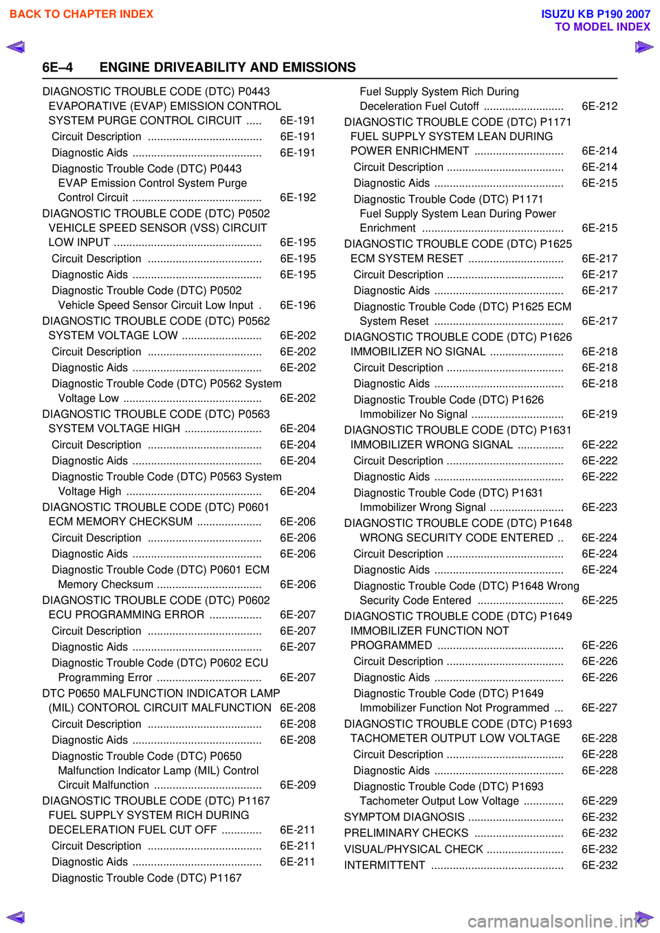
DIAGNOSTIC TROUBLE CODE (DTC) P0443 EVAPORATIVE (EVAP) EMISSION CONTROL
SYSTEM PURGE CONTROL CIRCUIT ..... 6E-191
Circuit Description ..................................... 6E-191
Diagnostic Aids .......................................... 6E-191
Diagnostic Trouble Code (DTC) P0443 EVAP Emission Control System Purge
Control Circuit .......................................... 6E-192
DIAGNOSTIC TROUBLE CODE (DTC) P0502 VEHICLE SPEED SENSOR (VSS) CIRCUIT
LOW INPUT ................................................ 6E-195
Circuit Description ..................................... 6E-195
Diagnostic Aids .......................................... 6E-195
Diagnostic Trouble Code (DTC) P0502 Vehicle Speed Sensor Circuit Low Input . 6E-196
DIAGNOSTIC TROUBLE CODE (DTC) P0562 SYSTEM VOLTAGE LOW .......................... 6E-202
Circuit Description ..................................... 6E-202
Diagnostic Aids .......................................... 6E-202
Diagnostic Trouble Code (DTC) P0562 System Voltage Low ............................................. 6E-202
DIAGNOSTIC TROUBLE CODE (DTC) P0563 SYSTEM VOLTAGE HIGH ......................... 6E-204
Circuit Description ..................................... 6E-204
Diagnostic Aids .......................................... 6E-204
Diagnostic Trouble Code (DTC) P0563 System Voltage High ............................................ 6E-204
DIAGNOSTIC TROUBLE CODE (DTC) P0601 ECM MEMORY CHECKSUM ..................... 6E-206
Circuit Description ..................................... 6E-206
Diagnostic Aids .......................................... 6E-206
Diagnostic Trouble Code (DTC) P0601 ECM Memory Checksum .................................. 6E-206
DIAGNOSTIC TROUBLE CODE (DTC) P0602 ECU PROGRAMMING ERROR ................. 6E-207
Circuit Description ..................................... 6E-207
Diagnostic Aids .......................................... 6E-207
Diagnostic Trouble Code (DTC) P0602 ECU Programming Error .................................. 6E-207
DTC P0650 MALFUNCTION INDICATOR LAMP (MIL) CONTOROL CIRCUIT MALFUNCTION 6E-208
Circuit Description ..................................... 6E-208
Diagnostic Aids .......................................... 6E-208
Diagnostic Trouble Code (DTC) P0650 Malfunction Indicator Lamp (MIL) Control
Circuit Malfunction ................................... 6E-209
DIAGNOSTIC TROUBLE CODE (DTC) P1167 FUEL SUPPLY SYSTEM RICH DURING
DECELERATION FUEL CUT OFF ............. 6E-211
Circuit Description ..................................... 6E-211
Diagnostic Aids .......................................... 6E-211
Diagnostic Trouble Code (DTC) P1167 Fuel Supply System Rich During
Deceleration Fuel Cutoff .......................... 6E-212
DIAGNOSTIC TROUBLE CODE (DTC) P1171 FUEL SUPPLY SYSTEM LEAN DURING
POWER ENRICHMENT ............................. 6E-214
Circuit Description ...................................... 6E-214
Diagnostic Aids .......................................... 6E-215
Diagnostic Trouble Code (DTC) P1171 Fuel Supply System Lean During Power
Enrichment .............................................. 6E-215
DIAGNOSTIC TROUBLE CODE (DTC) P1625 ECM SYSTEM RESET ............................... 6E-217
Circuit Description ...................................... 6E-217
Diagnostic Aids .......................................... 6E-217
Diagnostic Trouble Code (DTC) P1625 ECM System Reset .......................................... 6E-217
DIAGNOSTIC TROUBLE CODE (DTC) P1626 IMMOBILIZER NO SIGNAL ........................ 6E-218
Circuit Description ...................................... 6E-218
Diagnostic Aids .......................................... 6E-218
Diagnostic Trouble Code (DTC) P1626 Immobilizer No Signal .............................. 6E-219
DIAGNOSTIC TROUBLE CODE (DTC) P1631 IMMOBILIZER WRONG SIGNAL ............... 6E-222
Circuit Description ...................................... 6E-222
Diagnostic Aids .......................................... 6E-222
Diagnostic Trouble Code (DTC) P1631 Immobilizer Wrong Signal ........................ 6E-223
DIAGNOSTIC TROUBLE CODE (DTC) P1648 WRONG SECURITY CODE ENTERED .. 6E-224
Circuit Description ...................................... 6E-224
Diagnostic Aids .......................................... 6E-224
Diagnostic Trouble Code (DTC) P1648 Wrong Security Code Entered ............................ 6E-225
DIAGNOSTIC TROUBLE CODE (DTC) P1649 IMMOBILIZER FUNCTION NOT
PROGRAMMED ......................................... 6E-226
Circuit Description ...................................... 6E-226
Diagnostic Aids .......................................... 6E-226
Diagnostic Trouble Code (DTC) P1649 Immobilizer Function Not Programmed ... 6E-227
DIAGNOSTIC TROUBLE CODE (DTC) P1693 TACHOMETER OUTPUT LOW VOLTAGE 6E-228
Circuit Description ...................................... 6E-228
Diagnostic Aids .......................................... 6E-228
Diagnostic Trouble Code (DTC) P1693 Tachometer Output Low Voltage ............. 6E-229
SYMPTOM DIAGNOSIS ............................... 6E-232
PRELIMINARY CHECKS ............................. 6E-232
VISUAL/PHYSICAL CHECK ......................... 6E-232
INTERMITTENT ........................................... 6E-232
BACK TO CHAPTER INDEX
TO MODEL INDEX
ISUZU KB P190 2007
Page 2176 of 6020
6E–6 ENGINE DRIVEABILITY AND EMISSIONS
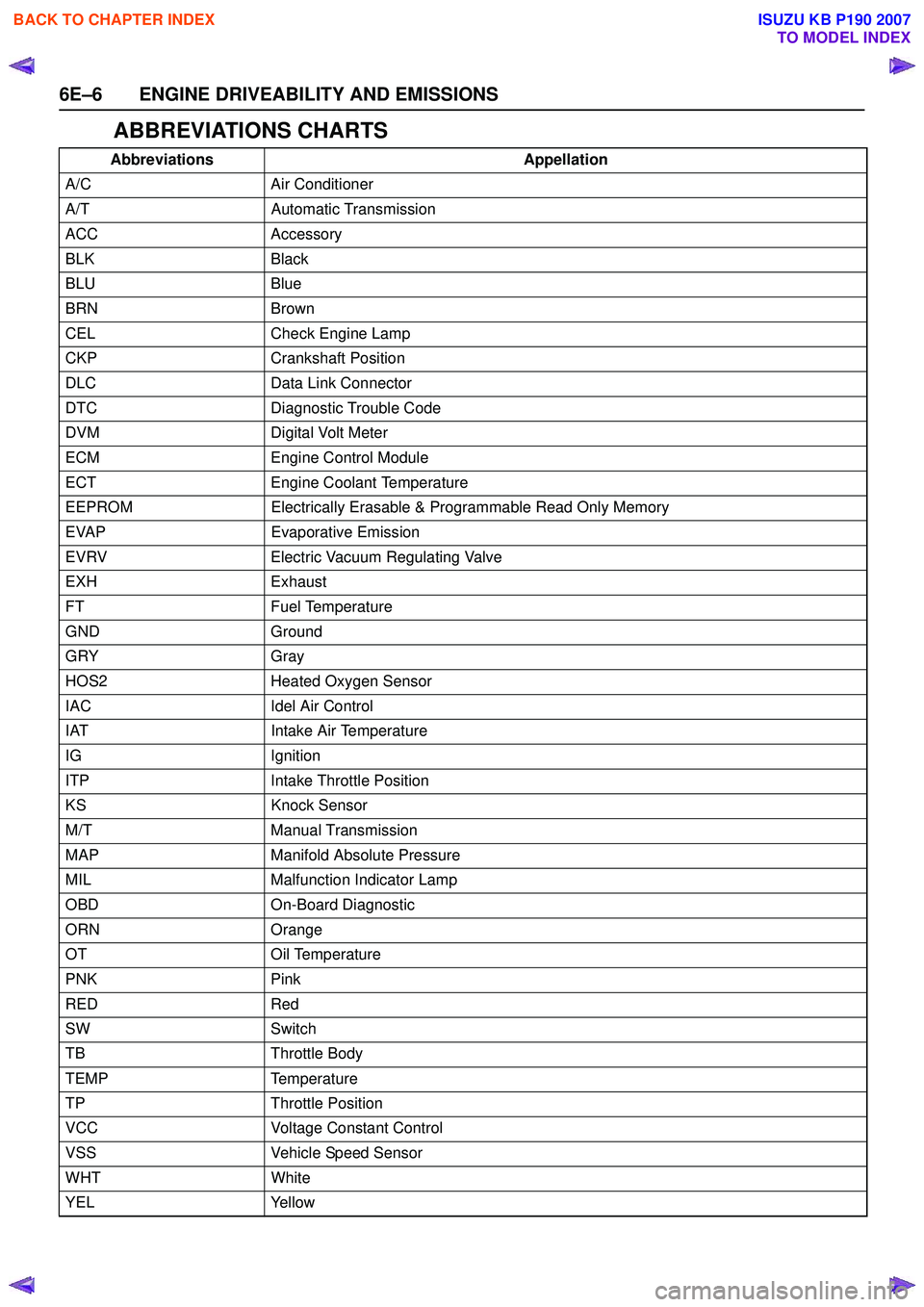
ABBREVIATIONS CHARTS
AbbreviationsAppellation
A/C Air Conditioner
A/T Automatic Transmission
ACC Accessory
BLK Black
BLU Blue
BRN Brown
CEL Check Engine Lamp
CKP Crankshaft Position
DLC Data Link Connector
DTC Diagnostic Trouble Code
DVM Digital Volt Meter
ECM Engine Control Module
ECT Engine Coolant Temperature
EEPROM Electrically Erasable & Programmable Read Only Memory
EVAP Evaporative Emission
EVRV Electric Vacuum Regulating Valve
EXH Exhaust
FT Fuel Temperature
GND Ground
GRY Gray
HOS2 Heated Oxygen Sensor
IAC Idel Air Control
IAT Intake Air Temperature
IG Ignition
ITP Intake Throttle Position
KS Knock Sensor
M/T Manual Transmission
MAP Manifold Absolute Pressure
MIL Malfunction Indicator Lamp
OBD On-Board Diagnostic
ORN Orange
OT Oil Temperature
PNK Pink
RED Red
SW Switch
TB Throttle Body
TEMP Temperature
TP Throttle Position
VCC Voltage Constant Control
VSS Vehicle Speed Sensor
WHT White
YEL Yellow
BACK TO CHAPTER INDEX
TO MODEL INDEX
ISUZU KB P190 2007
Page 2241 of 6020
ENGINE DRIVEABILITY AND EMISSIONS 6E–71
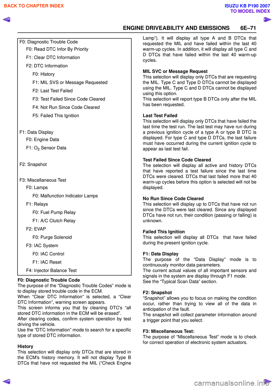
F0: Diagnostic Trouble Code
The purpose of the “Diagnostic Trouble Codes” mode is
to display stored trouble code in the ECM.
When “Clear DTC Information” is selected, a “Clear
DTC Information”, warning screen appears.
This screen informs you that by cleaning DTC's “all
stored DTC information in the ECM will be erased”.
After clearing codes, confirm system operation by test
driving the vehicle.
Use the “DTC Information” mode to search for a specific
type of stored DTC information.
History
This selection will display only DTCs that are stored in
the ECM's history memory. It will not display Type B
DTCs that have not requested the MIL (“Check Engine Lamp”). It will display all type A and B DTCs that
requested the MIL and have failed within the last 40
warm-up cycles. In addition, it will display all type C and
D DTCs that have failed within the last 40 warm-up
cycles.
MIL SVC or Message Request
This selection will display only DTCs that are requesting
the MIL. Type C and Type D DTCs cannot be displayed
using the MIL. Type C and D DTCs cannot be displayed
using this option.
This selection will report type B DTCs only after the MIL
has been requested.
Last Test Failed
This selection will display only DTCs that have failed the
last time the test run. The last test may have run during
a previous ignition cycle of a type A or type B DTC is
displayed. For type C and type D DTCs, the last failure
must have occurred during the current ignition cycle to
appear as last test fail.
Test Failed Since Code Cleared
The selection will display all active and history DTCs
that have reported a test failure since the last time
DTCs were cleared. DTCs that last failed more that 40
warm-up cycles before this option is selected will not be
displayed.
No Run Since Code Cleared
This selection will display up to DTCs that have not run
since the DTCs were last cleared. Since any displayed
DTCs have not run, their condition (passing or failing) is
unknown.
Failed This Ignition
This selection will display all DTCs that have failed
during the present ignition cycle.
F1: Data Display
The purpose of the “Data Display” mode is to
continuously monitor data parameters.
The current actual values of all important sensors and
signals in the system are display through F1 mode.
See the “Typical Scan Data” section.
F2: Snapshot
“Snapshot” allows you to focus on making the condition
occur, rather than trying to view all of the data in
anticipation of the fault.
The snapshot will collect parameter information around
a trigger point that you select.
F3: Miscellaneous Test:
The purpose of “Miscellaneous Test” mode is to check
for correct operation of electronic system actuators.
F0: Diagnostic Trouble Code
F0: Read DTC Infor By Priority
F1: Clear DTC Information
F2: DTC Information
F0: History
F1: MIL SVS or Message Requested
F2: Last Test Failed
F3: Test Failed Since Code Cleared
F4: Not Run Since Code Cleared
F5: Failed This Ignition
F1: Data Display
F0: Engine Data
F1: O2 Sensor Data
F2: Snapshot
F3: Miscellaneous Test
F0: Lamps
F0: Malfunction Indicator Lamps
F1: Relays
F0: Fuel Pump Relay
F1: A/C Clutch Relay
F2: EVAP
F0: Purge Solenoid
F3: IAC System
F0: IAC Control
F1: IAC Reset
F4: Injector Balance Test
BACK TO CHAPTER INDEX
TO MODEL INDEX
ISUZU KB P190 2007