2007 ISUZU KB P190 indicator
[x] Cancel search: indicatorPage 1467 of 6020
ENGINE MECHANICAL (4JK1/4JJ1) 6A-107
LNW 21BSH010401
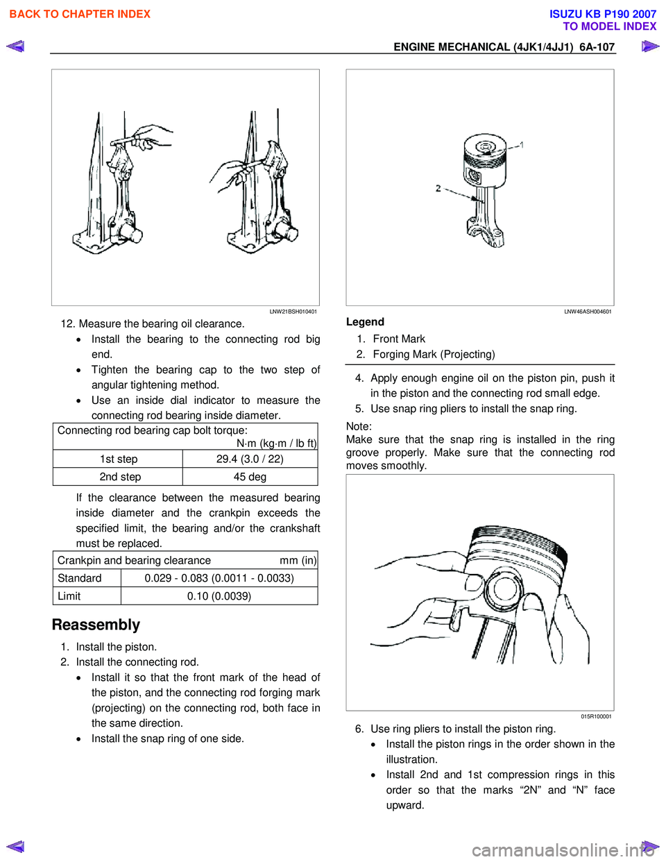
12. Measure the bearing oil clearance.
• Install the bearing to the connecting rod big
end.
• Tighten the bearing cap to the two step o
f
angular tightening method.
• Use an inside dial indicator to measure the
connecting rod bearing inside diameter.
Connecting rod bearing cap bolt torque:
N ⋅m (kg ⋅m / lb ft)
1st step 29.4 (3.0 / 22)
2nd step 45 deg
If the clearance between the measured bearing
inside diameter and the crankpin exceeds the
specified limit, the bearing and/or the crankshaft
must be replaced.
Crankpin and bearing clearance mm (in)
Standard 0.029 - 0.083 (0.0011 - 0.0033)
Limit 0.10 (0.0039)
Reassembly
1. Install the piston.
2. Install the connecting rod. • Install it so that the front mark of the head o
f
the piston, and the connecting rod forging mark
(projecting) on the connecting rod, both face in
the same direction.
• Install the snap ring of one side.
LNW 46ASH004601
Legend
1. Front Mark
2. Forging Mark (Projecting)
4. Apply enough engine oil on the piston pin, push it
in the piston and the connecting rod small edge.
5. Use snap ring pliers to install the snap ring.
Note:
Make sure that the snap ring is installed in the ring
groove properly. Make sure that the connecting rod
moves smoothly.
015R100001
6. Use ring pliers to install the piston ring.
• Install the piston rings in the order shown in the
illustration.
• Install 2nd and 1st compression rings in this
order so that the marks “2N” and “N” face
upward.
BACK TO CHAPTER INDEX
TO MODEL INDEX
ISUZU KB P190 2007
Page 1497 of 6020
ENGINE MECHANICAL (4JK1/4JJ1) 6A-137
16. Remove the piston cooling pipe.
RTW 76ASH001101
Inspection
1. Carefully remove water stains or other foreign
matters on the surface of the cylinder block.
• Be careful not to damage the cylinder block.
2. Carefully remove the liquid gasket on the crankcase mounting surface.
3. Clean up the cylinder block.
4. Visually inspect the cylinder block. • Conduct color check and hydraulic (o
r
pneumatic) test and if you find a crack or other
damage, replace the cylinder block.
RTW 76ASH000801
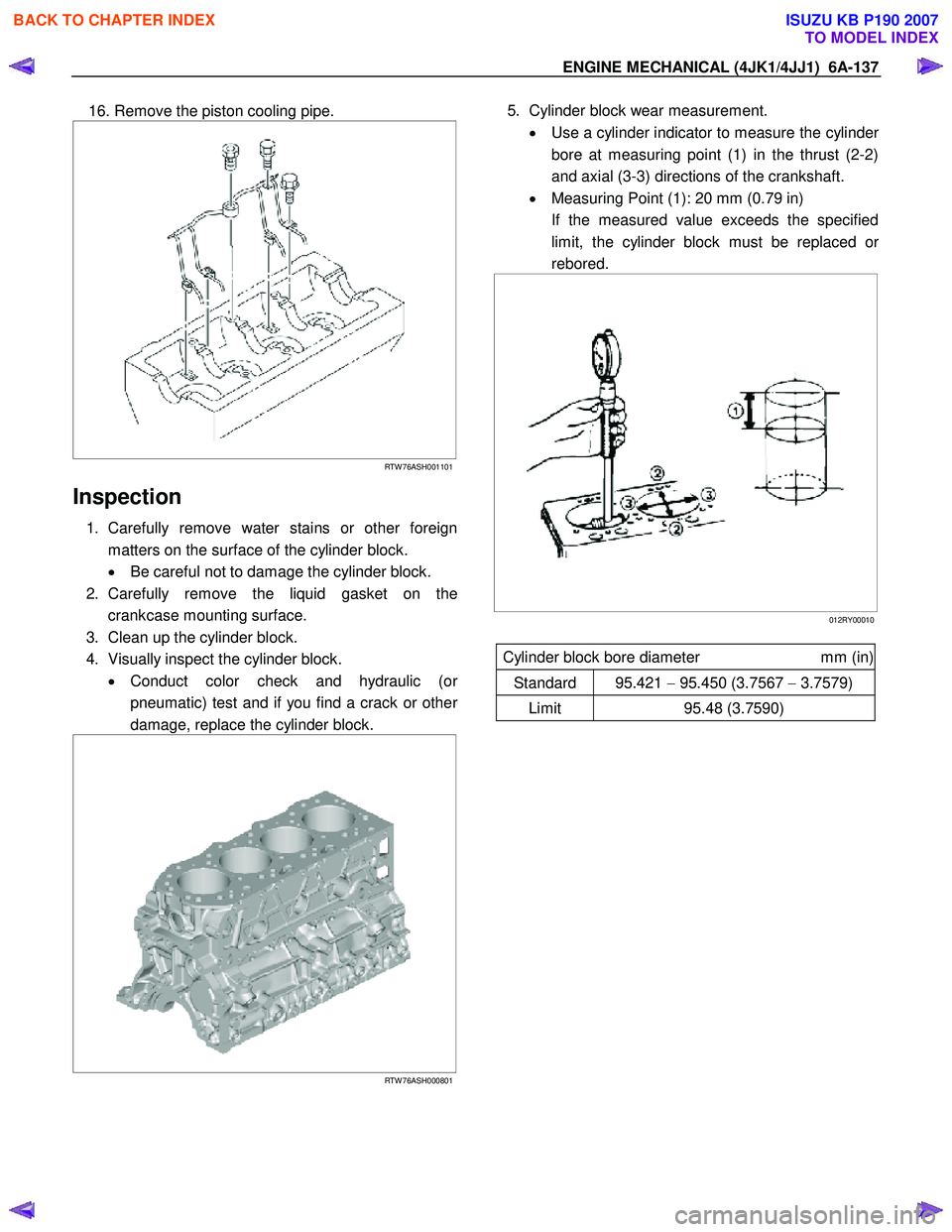
5. Cylinder block wear measurement.
• Use a cylinder indicator to measure the cylinde
r
bore at measuring point (1) in the thrust (2-2)
and axial (3-3) directions of the crankshaft.
• Measuring Point (1): 20 mm (0.79 in)
If the measured value exceeds the specified limit, the cylinder block must be replaced o
r
rebored.
012RY00010
Cylinder block bore diameter mm (in)
Standard 95.421 − 95.450 (3.7567 − 3.7579)
Limit 95.48 (3.7590)
BACK TO CHAPTER INDEX
TO MODEL INDEX
ISUZU KB P190 2007
Page 1548 of 6020
FUEL SYSTEM (4JK1/4JJ1) 6C-7
g. Check that the warning lamp in the meter is off.
2. Draining with drain plug in engine room. a. W ith the engine off, open the engine hood and loosen the drain plug (1) located on the left
hand side of the engine room. (3-4 turns)
b. Turn the starter switch to the “ON” position fo
r
10 seconds, and then turn the starter switch to
the “OFF” position for 10 seconds. Then, once
again turn the starter switch to the “ON”
position for 10 seconds.
c. Tighten the drain plug firmly.
d.
After starting the engine, check that there is no
fuel leakage from the drain plug. Also check
that the water separator indicator has turned
off.
RTW 76CSH001301
NOTE:
• If the water separator requires frequent draining,
have the fuel tank drained at your ISUZU/GM
Dealer.
• Be sure to stop the engine when draining the fuel
tank.
• Confirm that there are no combustible materials
under the drain hose, and use a receptacle to
catch the drained water.
Engine starting cautions
• Before starting the engine, turn the ignition switch
to the “ON” position. W ait 15 seconds. Return the
switch to the “LOCK” position. Repeat this
procedure 5 times.
• After starting the engine, allow it to idle for 10
minutes.
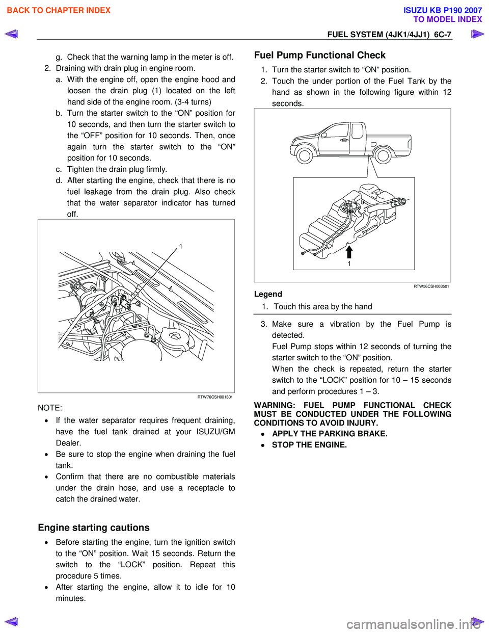
Fuel Pump Functional Check
1. Turn the starter switch to “ON” position.
2. Touch the under portion of the Fuel Tank by the hand as shown in the following figure within 12
seconds.
RTW 56CSH003501
Legend
1. Touch this area by the hand
3. Make sure a vibration by the Fuel Pump is
detected.
Fuel Pump stops within 12 seconds of turning the starter switch to the “ON” position.
W hen the check is repeated, return the starte
r
switch to the “LOCK” position for 10 – 15 seconds
and perform procedures 1 – 3.
WARNING: FUEL PUMP FUNCTIONAL CHECK
MUST BE CONDUCTED UNDER THE FOLLOWING
CONDITIONS TO AVOID INJURY.
•
••
•
APPLY THE PARKING BRAKE.
•
••
•
STOP THE ENGINE.
BACK TO CHAPTER INDEX
TO MODEL INDEX
ISUZU KB P190 2007
Page 1617 of 6020
ENGINE ELECTRICAL (4JK1/4JJ1) 6D-29
Pre-Heating System
Inspection and Repair
Make the necessary adjustments, repairs, and part
replacement if excessive wear of damage is discovered
during inspection.
Visual Check
Check the main fuses and glow indicator for damage.
Replace the part(s) if required.
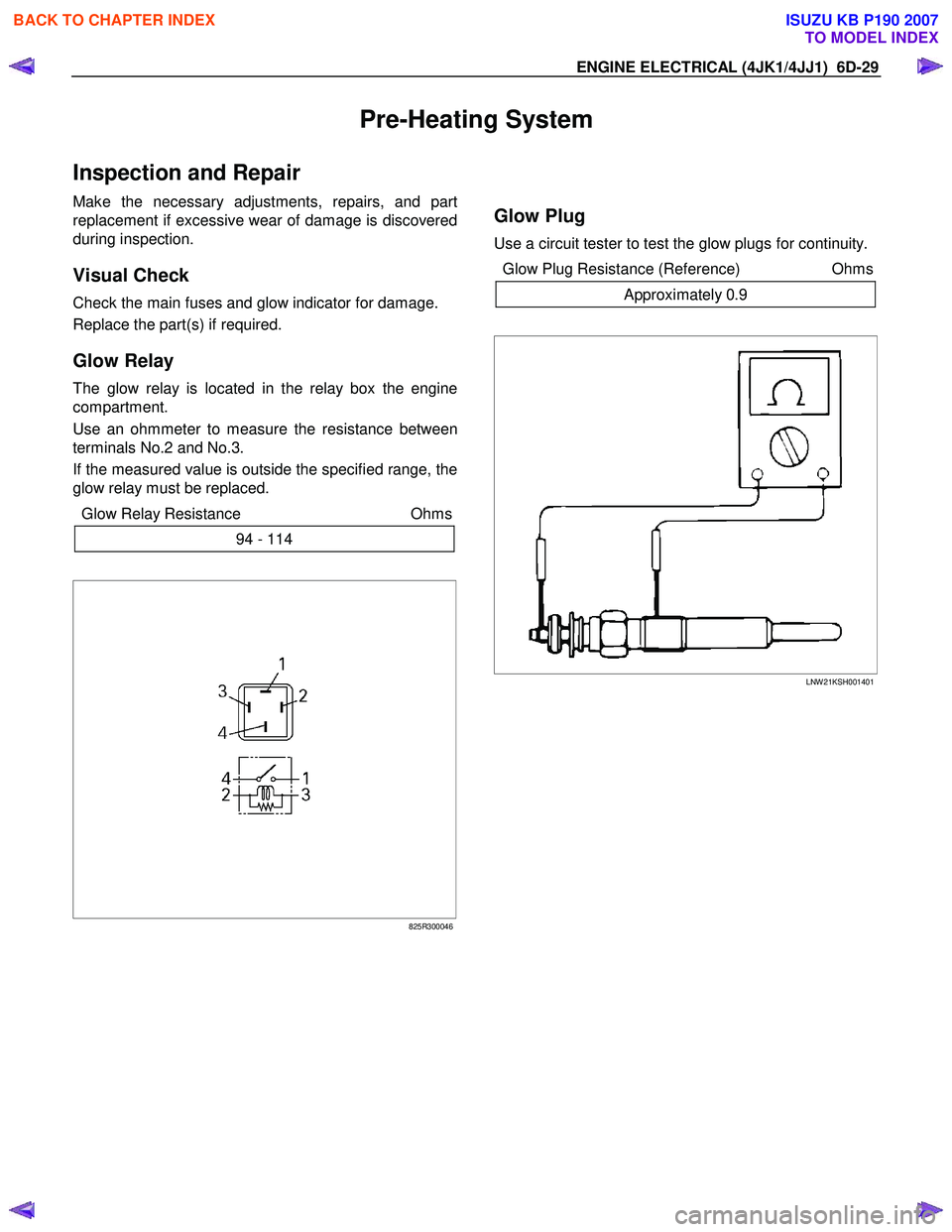
Glow Relay
The glow relay is located in the relay box the engine
compartment.
Use an ohmmeter to measure the resistance between
terminals No.2 and No.3.
If the measured value is outside the specified range, the
glow relay must be replaced.
Glow Relay Resistance Ohms
94 - 114
825R300046
Glow Plug
Use a circuit tester to test the glow plugs for continuity.
Glow Plug Resistance (Reference) Ohms
Approximately 0.9
LNW 21KSH001401
BACK TO CHAPTER INDEX
TO MODEL INDEX
ISUZU KB P190 2007
Page 1621 of 6020
6E-4 ENGINE CONTROL SYSTEM (4JK1/4JJ1)
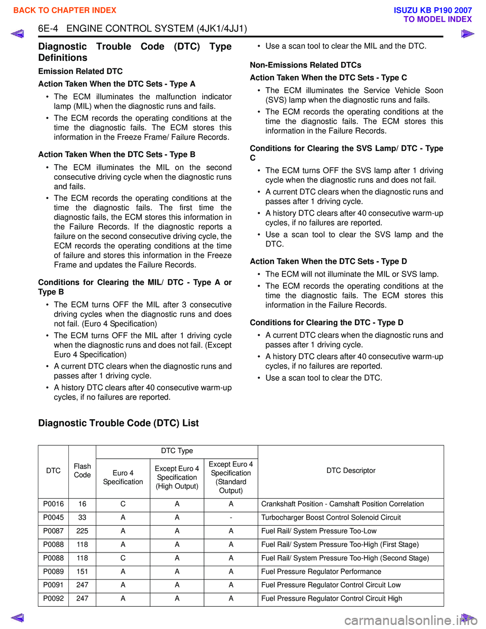
Diagnostic Trouble Code (DTC) Type
Definitions
Emission Related DTC
Action Taken When the DTC Sets - Type A • The ECM illuminates the malfunction indicator lamp (MIL) when the diagnostic runs and fails.
• The ECM records the operating conditions at the time the diagnostic fails. The ECM stores this
information in the Freeze Frame/ Failure Records.
Action Taken When the DTC Sets - Type B • The ECM illuminates the MIL on the second consecutive driving cycle when the diagnostic runs
and fails.
• The ECM records the operating conditions at the time the diagnostic fails. The first time the
diagnostic fails, the ECM stores this information in
the Failure Records. If the diagnostic reports a
failure on the second consecutive driving cycle, the
ECM records the operating conditions at the time
of failure and stores this information in the Freeze
Frame and updates the Failure Records.
Conditions for Clearing the MIL/ DTC - Type A or
Ty p e B
• The ECM turns OFF the MIL after 3 consecutive driving cycles when the diagnostic runs and does
not fail. (Euro 4 Specification)
• The ECM turns OFF the MIL after 1 driving cycle when the diagnostic runs and does not fail. (Except
Euro 4 Specification)
• A current DTC clears when the diagnostic runs and passes after 1 driving cycle.
• A history DTC clears after 40 consecutive warm-up cycles, if no failures are reported. • Use a scan tool to clear the MIL and the DTC.
Non-Emissions Related DTCs
Action Taken When the DTC Sets - Type C
• The ECM illuminates the Service Vehicle Soon (SVS) lamp when the diagnostic runs and fails.
• The ECM records the operating conditions at the time the diagnostic fails. The ECM stores this
information in the Failure Records.
Conditions for Clearing the SVS Lamp/ DTC - Type
C
• The ECM turns OFF the SVS lamp after 1 driving cycle when the diagnostic runs and does not fail.
• A current DTC clears when the diagnostic runs and passes after 1 driving cycle.
• A history DTC clears after 40 consecutive warm-up cycles, if no failures are reported.
• Use a scan tool to clear the SVS lamp and the DTC.
Action Taken When the DTC Sets - Type D • The ECM will not illuminate the MIL or SVS lamp.
• The ECM records the operating conditions at the time the diagnostic fails. The ECM stores this
information in the Failure Records.
Conditions for Clearing the DTC - Type D • A current DTC clears when the diagnostic runs and passes after 1 driving cycle.
• A history DTC clears after 40 consecutive warm-up cycles, if no failures are reported.
• Use a scan tool to clear the DTC.
Diagnostic Trouble Code (DTC) List
DTC Flash
Code DTC Type
DTC Descriptor
Euro 4
Specification Except Euro 4
Specification
(High Output) Except Euro 4
Specification
(Standard Output)
P0016 16 C AA Crankshaft Position - Camshaft Position Correlation
P0045 33 A A- Turbocharger Boost Control Solenoid Circuit
P0087 225 A AA Fuel Rail/ System Pressure Too-Low
P0088 118 A AA Fuel Rail/ System Pressure Too-High (First Stage)
P0088 118 C AA Fuel Rail/ System Pressure Too-High (Second Stage)
P0089 151 A AA Fuel Pressure Regulator Performance
P0091 247 A AA Fuel Pressure Regulator Control Circuit Low
P0092 247 A AA Fuel Pressure Regulator Control Circuit High
BACK TO CHAPTER INDEX
TO MODEL INDEX
ISUZU KB P190 2007
Page 1623 of 6020
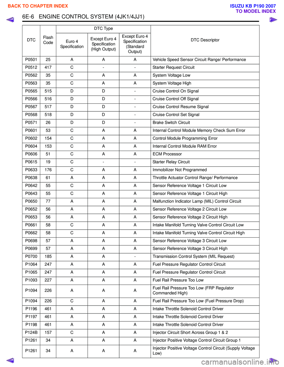
6E-6 ENGINE CONTROL SYSTEM (4JK1/4JJ1)
P0501 25 AAA Vehicle Speed Sensor Circuit Range/ Performance
P0512 417 C -- Starter Request Circuit
P0562 35 C AA System Voltage Low
P0563 35 C AA System Voltage High
P0565 515 D D- Cruise Control On Signal
P0566 516 D D- Cruise Control Off Signal
P0567 517 D D- Cruise Control Resume Signal
P0568 518 D D- Cruise Control Set Signal
P0571 26 D D- Brake Switch Circuit
P0601 53 C AA Internal Control Module Memory Check Sum Error
P0602 154 C AA Control Module Programming Error
P0604 153 C AA Internal Control Module RAM Error
P0606 51 C AA ECM Processor
P0615 19 C -- Starter Relay Circuit
P0633 176 C AA Immobilizer Not Programmed
P0638 61 A AA Throttle Actuator Control Range/ Performance
P0642 55 C AA Sensor Reference Voltage 1 Circuit Low
P0643 55 C AA Sensor Reference Voltage 1 Circuit High
P0650 77 A AA Malfunction Indicator Lamp (MIL) Control Circuit
P0652 56 A AA Sensor Reference Voltage 2 Circuit Low
P0653 56 A AA Sensor Reference Voltage 2 Circuit High
P0661 58 C AA Intake Manifold Turning Valve Control Circuit Low
P0662 58 C AA Intake Manifold Turning Valve Control Circuit High
P0698 57 A AA Sensor Reference Voltage 3 Circuit Low
P0699 57 A AA Sensor Reference Voltage 3 Circuit High
P0700 185 A A- Transmission Control System (MIL Request)
P1064 247 A AA Fuel Pressure Regulator Control Circuit
P1065 247 A AA Fuel Pressure Regulator Control Circuit
P1093 227 A AA Fuel Rail Pressure Too Low
P1094 226 A AAFuel Rail Pressure Too Low (FRP Regulator
Commanded High)
P1094 226 C AA Fuel Rail Pressure Too Low (Fuel Pressure Drop)
P1196 461 A AA Intake Throttle Solenoid Control Driver
P1197 461 A AA Intake Throttle Solenoid Control Driver
P1198 461 A AA Intake Throttle Solenoid Control Driver
P124B 157 C AA Injector Circuit Short Across Group 1 & 2
P1261 34 A AA Injector Positive Voltage Control Circuit Group 1
P1261 34 A AAInjector Positive Voltage Control Circuit (Supply Voltage
Low)
DTC
Flash
Code DTC Type
DTC Descriptor
Euro 4
Specification Except Euro 4
Specification
(High Output) Except Euro 4
Specification (Standard Output)
BACK TO CHAPTER INDEX
TO MODEL INDEX
ISUZU KB P190 2007
Page 1661 of 6020
6E-44 ENGINE CONTROL SYSTEM (4JK1/4JJ1)
Diagnostic Starting Point - Engine Controls
Begin the system diagnosis with Diagnostic System
Check - Engine Controls. The Diagnostic System
Check - Engine Controls will provide the following
information:
• The identification of the control modules which command the system.
• The ability of the control modules to communicate through the serial data circuit.
• The identification of any stored diagnostic trouble codes (DTCs) and the their statuses.
The use of the Diagnostic System Check - Engine
Controls will identify the correct procedure for
diagnosing the system and where the procedure is
located.
Important: Engine Control System Check Sheet must
be used to verify the complaint vehicle, you need to
know the correct (normal) operating behavior of the
system and verify that the customer complaint is a valid
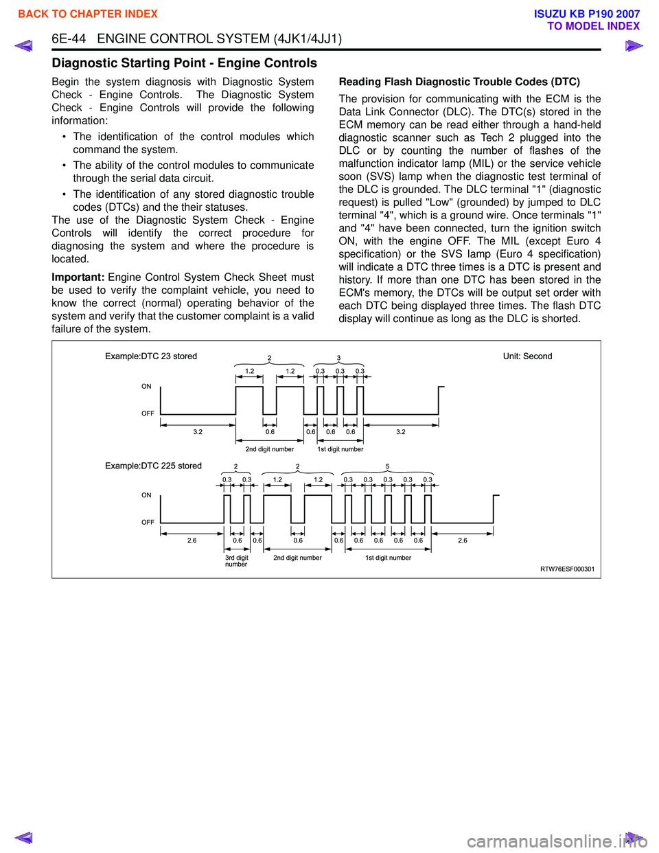
failure of the system. Reading Flash Diagnostic Trouble Codes (DTC)
The provision for communicating with the ECM is the
Data Link Connector (DLC). The DTC(s) stored in the
ECM memory can be read either through a hand-held
diagnostic scanner such as Tech 2 plugged into the
DLC or by counting the number of flashes of the
malfunction indicator lamp (MIL) or the service vehicle
soon (SVS) lamp when the diagnostic test terminal of
the DLC is grounded. The DLC terminal "1" (diagnostic
request) is pulled "Low" (grounded) by jumped to DLC
terminal "4", which is a ground wire. Once terminals "1"
and "4" have been connected, turn the ignition switch
ON, with the engine OFF. The MIL (except Euro 4
specification) or the SVS lamp (Euro 4 specification)
will indicate a DTC three times is a DTC is present and
history. If more than one DTC has been stored in the
ECM's memory, the DTCs will be output set order with
each DTC being displayed three times. The flash DTC
display will continue as long as the DLC is shorted.
RTW76ESF000301
ON
OFF
ON
OFF
1.2
3.2
2.62.6
2nd digit number1st digit number
3.20.6 2
1.2
0.60.60.6
0.30.30.3
0.30.30.30.30.3
Example:DTC 23 stored
Unit: Second
Example:DTC 225 stored
3rd digit
number 2nd digit number1st digit number
0.60.60.60.60.60.60.60.6
3
0.30.31.21.2
2
25
BACK TO CHAPTER INDEX
TO MODEL INDEX
ISUZU KB P190 2007
Page 1666 of 6020
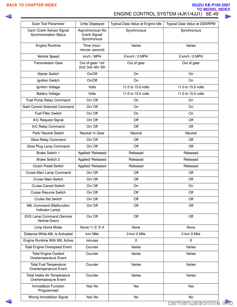
ENGINE CONTROL SYSTEM (4JK1/4JJ1) 6E-49
Cam/ Crank Sensor Signal Synchronization Status Asynchronous/ No
Crank Signal/ Synchronous Synchronous Synchronous
Engine Runtime Time (hour: minute: second) Va r i e s
Va r i e s
Vehicle Speed km/h / MPH0 km/h / 0 MPH 0 km/h / 0 MPH
Transmission Gear Out of gear/ 1st/ 2nd/ 3rd/ 4th/ 5th Out of gear
Out of gear
Starter Switch On/OffOn On
Ignition Switch On/OffOn On
Ignition Voltage Volts11.0 to 15.0 volts 11.0 to 15.0 volts
Battery Voltage Volts11.0 to 15.0 volts 11.0 to 15.0 volts
Fuel Pump Relay Command On/ Off OnOn
Swirl Control Solenoid Command On/ Off OnOn
Fuel Filter Switch On/ OffOn On
A/C Request Signal On/ OffOff Off
A/C Relay Command On/ OffOff Off
Park/ Neutral Switch Neutral/ In Gear NeutralNeutral
Glow Relay Command On/ OffOff Off
Glow Plug Lamp Command On/ Off OffOff
Brake Switch 1 Applied/ Released Released Released
Brake Switch 2 Applied/ Released Released Released
Clutch Pedal Switch Applied/ Released ReleasedReleased
Cruise Main Lamp Command On/ Off OffOff
Cruise Main Switch On/ OffOff Off
Cruise Cancel Switch On/ OffOn On
Cruise Resume Switch On/ OffOff Off
Cruise Set Switch On/ OffOff Off
MIL Command (Malfunction Indicator Lamp) On/ Off
Off Off
SVS Lamp Command (Service Vehicle Soon) On/ Off
Off Off
Limp Home Mode None/ 1/ 2/ 3/ 4 None None
Distance While MIL is Activated km/ Mile 0 km/ 0 Mile0 km/ 0 Mile
Engine Runtime With MIL Active minutes 00
Total Engine Overspeed Event Counter VariesVaries
Total Engine Coolant
Overtemperature Event Counter
Varies Varies
Total Fuel Temperature
Overtemperatrure Event Counter
Varies Varies
Total Intake Air Temperature Overtemperaure Event Counter
Varies Varies
Immobilizer Function Programmed Ye s / N o
Ye s Ye s
Wrong Immobilizer Signal Yes/ NoNo No
Scan Tool Parameter Units Displayed Typical Data Value at Engine Idle Typical Data Value at 2000RPM
BACK TO CHAPTER INDEX
TO MODEL INDEX
ISUZU KB P190 2007