2007 ISUZU KB P190 indicator
[x] Cancel search: indicatorPage 1823 of 6020
6E-206 ENGINE CONTROL SYSTEM (4JK1/4JJ1)
DTC P0650 (Flash Code 77)
Circuit Description
The malfunction indicator lamp (MIL) is located on the
instrument panel (IP) cluster. The MIL informs the
driver that an emission system fault has occurred and
that the engine control system requires service.
The ECM monitors the MIL control circuit for conditions
that are incorrect for the commanded state of the MIL.
For example, a failure condition exists if the ECM
detects low voltage when the MIL is commanded OFF,
or high voltage when the MIL is commanded ON. If the
ECM detects an improper voltage level on the control
circuit, this DTC will set.
Condition for Running the DTC • The ignition voltage is more than 9 volts.
• The ignition switch is ON.
Condition for Setting the DTC
Either of following condition is met: • The ECM detects a low voltage condition on the MIL control circuit when the lamp is commanded
OFF. • The ECM detects a high voltage condition on the
MIL control circuit when the lamp is commanded
ON.
Action Taken When the DTC Sets • The ECM illuminates the MIL when the diagnostic runs and fails. Refer to DTC Type Definitions for
Action Taken When the DTC Sets - Type A.
Condition for Clearing the DTC • Refer to DTC Type Definitions for Condition for Clearing the MIL/ DTC - Type A.
Diagnostic Aids • If an intermittent condition is suspected, refer to Intermittent Conditions in this section.
Schematic Reference: Engine Controls Schematics
Connector End View Reference: Engine Controls
Connector End Views or ECM Connector End Views
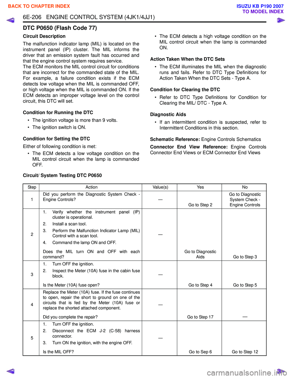
Circuit/ System Testing DTC P0650
Step Action Value(s)Yes No
1 Did you perform the Diagnostic System Check -
Engine Controls? —
Go to Step 2 Go to Diagnostic
System Check -
Engine Controls
2 1. Verify whether the instrument panel (IP)
cluster is operational.
2. Install a scan tool.
3. Perform the Malfunction Indicator Lamp (MIL) Control with a scan tool.
4. Command the lamp ON and OFF.
Does the MIL turn ON and OFF with each
command? —
Go to Diagnostic Aids Go to Step 3
3 1. Turn OFF the ignition.
2. Inspect the Meter (10A) fuse in the cabin fuse block.
Is the Meter (10A) fuse open? —
Go to Step 4 Go to Step 5
4 Replace the Meter (10A) fuse. If the fuse continues
to open, repair the short to ground on one of the
circuits that is fed by the Meter (10A) fuse or
replace the shorted attached component.
Did you complete the repair? —
Go to Step 17
—
51. Turn OFF the ignition.
2. Disconnect the ECM J-2 (C-58) harness connector.
3. Turn ON the ignition, with the engine OFF.
Is the MIL OFF? —
Go to Sep 6 Go to Step 12
BACK TO CHAPTER INDEX
TO MODEL INDEX
ISUZU KB P190 2007
Page 1838 of 6020
ENGINE CONTROL SYSTEM (4JK1/4JJ1) 6E-221
DTC P0700 (Flash Code 185)
Circuit Description
The transmission control module (TCM) requests to
illuminate the malfunction indicator lamp (MIL) via a
controller area network (CAN) communication bus to
the ECM when the TCM sets a MIL request DTC(s). If
the ECM detects the MIL illumination request signal,
this DTC will set.
Condition for Running the DTC • DTCs U0001 and U0101 are not set.
• The ignition switch is ON.
Condition for Setting the DTC • The ECM detects that the MIL illumination is requested by the TCM.
Action Taken When the DTC Sets • The ECM illuminates MIL when the diagnostic runs and fails. Refer to DTC Type Definitions for Action
Taken When the DTC Sets - Type A. • The ECM inhibits cruise control.
Condition for Clearing the DTC • Refer to DTC Type Definitions for Condition for Clearing the MIL/ DTC - Type A.
Diagnostic Aids • Under normal conditions if the TCM sets a DTC that requests the MIL to be illuminated, P0700 will
set.
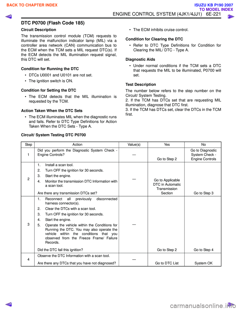
Test Description
The number below refers to the step number on the
Circuit/ System Testing.
2. If the TCM has DTCs set that are requesting MIL
illumination, diagnose that DTC first.
3. If the TCM has DTCs set, clear the DTCs in the TCM
first.
Circuit/ System Testing DTC P0700
Step Action Value(s)Yes No
1 Did you perform the Diagnostic System Check -
Engine Controls? —
Go to Step 2 Go to Diagnostic
System Check -
Engine Controls
2 1. Install a scan tool.
2. Turn OFF the ignition for 30 seconds.
3. Start the engine.
4. Monitor the transmission DTC Information with a scan tool.
Are there any transmission DTCs set? —
Go to Applicable
DTC in Automatic
Transmission Section Go to Step 3
3 1. Reconnect all previously disconnected
harness connector(s).
2. Clear the DTCs with a scan tool.
3. Turn OFF the ignition for 30 seconds.
4. Start the engine.
5. Operate the vehicle within the Conditions for Running the DTC. You may also operate the
vehicle within the conditions that you
observed from the Freeze Frame/ Failure
Records.
Did the DTC fail this ignition? —
Go to Step 2 Go to Step 4
4 Observe the DTC Information with a scan tool.
Are there any DTCs that you have not diagnosed? —
Go to DTC List System OK
BACK TO CHAPTER INDEX
TO MODEL INDEX
ISUZU KB P190 2007
Page 1923 of 6020
6E-306 ENGINE CONTROL SYSTEM (4JK1/4JJ1)
Glow Control System Check
Description
The glow control system consists of the ECM, the glow
relay, the glow indicator lamp and glow plugs. The glow
control system is operated when the engine coolant
temperature is low, which allows easier engine starting.
The ECM commands the glow relay ON for a certain
length of time at ignition switch is ON with engine OFF.
In after glow phase, the glow plugs remain energized
for a certain period with engine run.
Glow Control Operation • The glow indicator lamp illuminates between 0.5 seconds to 7 seconds depending upon the engine
coolant temperature. • The pre glow control system operates when the
engine coolant temperature is less than 30 °C
(86 °F).
• The after glow control system operates when the engine coolant temperature is less than 60 °C
(140 °F).
Schematic Reference: Engine Controls Schematics
Connector End View Reference: Engine Controls
Connector End Views or ECM Connector End Views
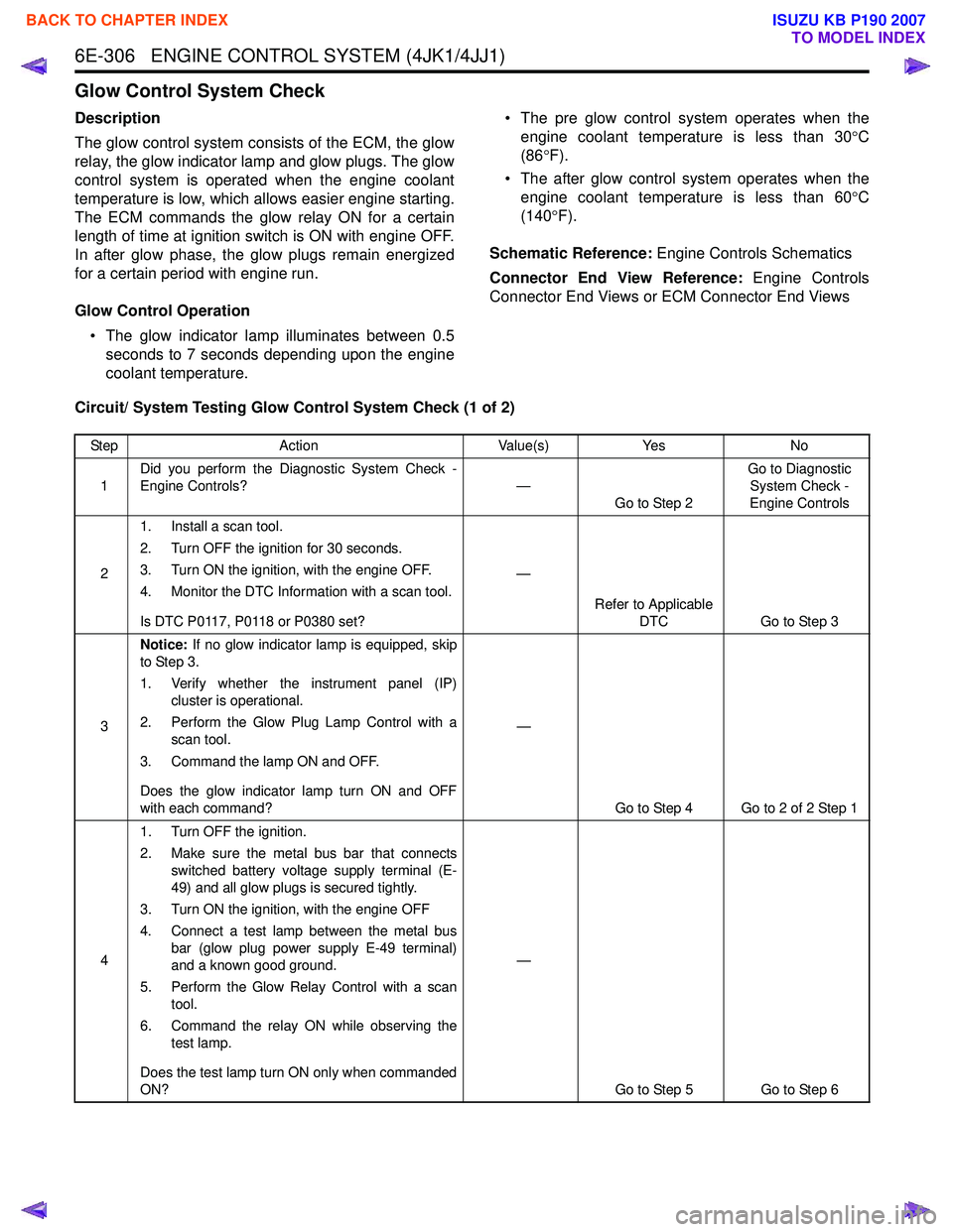
Circuit/ System Testing Glow Control System Check (1 of 2)
Step Action Value(s)Yes No
1 Did you perform the Diagnostic System Check -
Engine Controls? —
Go to Step 2 Go to Diagnostic
System Check -
Engine Controls
2 1. Install a scan tool.
2. Turn OFF the ignition for 30 seconds.
3. Turn ON the ignition, with the engine OFF.
4. Monitor the DTC Information with a scan tool.
Is DTC P0117, P0118 or P0380 set? —
Refer to Applicable DTC Go to Step 3
3 Notice:
If no glow indicator lamp is equipped, skip
to Step 3.
1. Verify whether the instrument panel (IP) cluster is operational.
2. Perform the Glow Plug Lamp Control with a scan tool.
3. Command the lamp ON and OFF.
Does the glow indicator lamp turn ON and OFF
with each command? —
Go to Step 4 Go to 2 of 2 Step 1
4 1. Turn OFF the ignition.
2. Make sure the metal bus bar that connects switched battery voltage supply terminal (E-
49) and all glow plugs is secured tightly.
3. Turn ON the ignition, with the engine OFF
4. Connect a test lamp between the metal bus bar (glow plug power supply E-49 terminal)
and a known good ground.
5. Perform the Glow Relay Control with a scan tool.
6. Command the relay ON while observing the test lamp.
Does the test lamp turn ON only when commanded
ON? —
Go to Step 5 Go to Step 6
BACK TO CHAPTER INDEX
TO MODEL INDEX
ISUZU KB P190 2007
Page 1925 of 6020
6E-308 ENGINE CONTROL SYSTEM (4JK1/4JJ1)
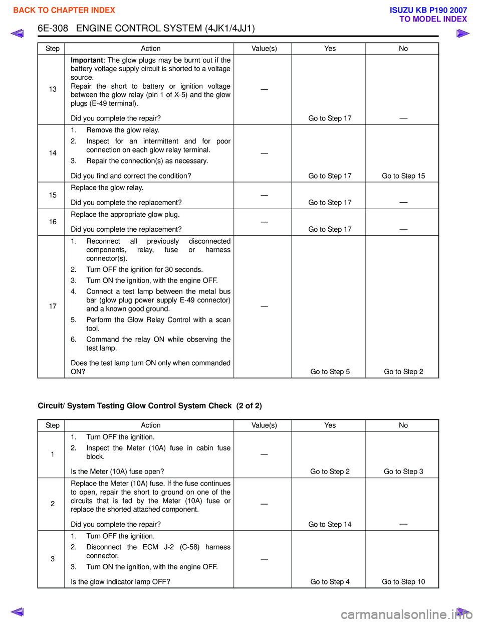
Circuit/ System Testing Glow Control System Check (2 of 2)
13Important
: The glow plugs may be burnt out if the
battery voltage supply circuit is shorted to a voltage
source.
Repair the short to battery or ignition voltage
between the glow relay (pin 1 of X-5) and the glow
plugs (E-49 terminal).
Did you complete the repair? —
Go to Step 17
—
141. Remove the glow relay.
2. Inspect for an intermittent and for poor connection on each glow relay terminal.
3. Repair the connection(s) as necessary.
Did you find and correct the condition? —
Go to Step 17 Go to Step 15
15 Replace the glow relay.
Did you complete the replacement? —
Go to Step 17
—
16Replace the appropriate glow plug.
Did you complete the replacement? —
Go to Step 17—
171. Reconnect all previously disconnected
components, relay, fuse or harness
connector(s).
2. Turn OFF the ignition for 30 seconds.
3. Turn ON the ignition, with the engine OFF.
4. Connect a test lamp between the metal bus bar (glow plug power supply E-49 connector)
and a known good ground.
5. Perform the Glow Relay Control with a scan tool.
6. Command the relay ON while observing the test lamp.
Does the test lamp turn ON only when commanded
ON? —
Go to Step 5 Go to Step 2
Step
Action Value(s)Yes No
Step Action Value(s)Yes No
1 1. Turn OFF the ignition.
2. Inspect the Meter (10A) fuse in cabin fuse block.
Is the Meter (10A) fuse open? —
Go to Step 2 Go to Step 3
2 Replace the Meter (10A) fuse. If the fuse continues
to open, repair the short to ground on one of the
circuits that is fed by the Meter (10A) fuse or
replace the shorted attached component.
Did you complete the repair? —
Go to Step 14
—
31. Turn OFF the ignition.
2. Disconnect the ECM J-2 (C-58) harness connector.
3. Turn ON the ignition, with the engine OFF.
Is the glow indicator lamp OFF? —
Go to Step 4 Go to Step 10
BACK TO CHAPTER INDEX
TO MODEL INDEX
ISUZU KB P190 2007
Page 1926 of 6020
ENGINE CONTROL SYSTEM (4JK1/4JJ1) 6E-309
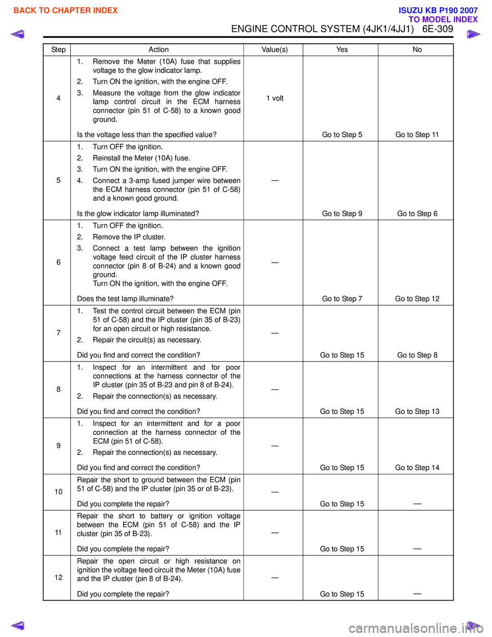
41. Remove the Meter (10A) fuse that supplies
voltage to the glow indicator lamp.
2. Turn ON the ignition, with the engine OFF.
3. Measure the voltage from the glow indicator lamp control circuit in the ECM harness
connector (pin 51 of C-58) to a known good
ground.
Is the voltage less than the specified value? 1 volt
Go to Step 5 Go to Step 11
5 1. Turn OFF the ignition.
2. Reinstall the Meter (10A) fuse.
3. Turn ON the ignition, with the engine OFF.
4. Connect a 3-amp fused jumper wire between the ECM harness connector (pin 51 of C-58)
and a known good ground.
Is the glow indicator lamp illuminated? —
Go to Step 9 Go to Step 6
6 1. Turn OFF the ignition.
2. Remove the IP cluster.
3. Connect a test lamp between the ignition voltage feed circuit of the IP cluster harness
connector (pin 8 of B-24) and a known good
ground.
Turn ON the ignition, with the engine OFF.
Does the test lamp illuminate? —
Go to Step 7 Go to Step 12
7 1. Test the control circuit between the ECM (pin
51 of C-58) and the IP cluster (pin 35 of B-23)
for an open circuit or high resistance.
2. Repair the circuit(s) as necessary.
Did you find and correct the condition? —
Go to Step 15 Go to Step 8
8 1. Inspect for an intermittent and for poor
connections at the harness connector of the
IP cluster (pin 35 of B-23 and pin 8 of B-24).
2. Repair the connection(s) as necessary.
Did you find and correct the condition? —
Go to Step 15 Go to Step 13
9 1. Inspect for an intermittent and for a poor
connection at the harness connector of the
ECM (pin 51 of C-58).
2. Repair the connection(s) as necessary.
Did you find and correct the condition? —
Go to Step 15 Go to Step 14
10 Repair the short to ground between the ECM (pin
51 of C-58) and the IP cluster (pin 35 or of B-23).
Did you complete the repair? —
Go to Step 15
—
11Repair the short to battery or ignition voltage
between the ECM (pin 51 of C-58) and the IP
cluster (pin 35 of B-23).
Did you complete the repair? —
Go to Step 15
—
12Repair the open circuit or high resistance on
ignition the voltage feed circuit the Meter (10A) fuse
and the IP cluster (pin 8 of B-24).
Did you complete the repair? —
Go to Step 15
—
Step Action Value(s)Yes No
BACK TO CHAPTER INDEX
TO MODEL INDEX
ISUZU KB P190 2007
Page 1927 of 6020
6E-310 ENGINE CONTROL SYSTEM (4JK1/4JJ1)
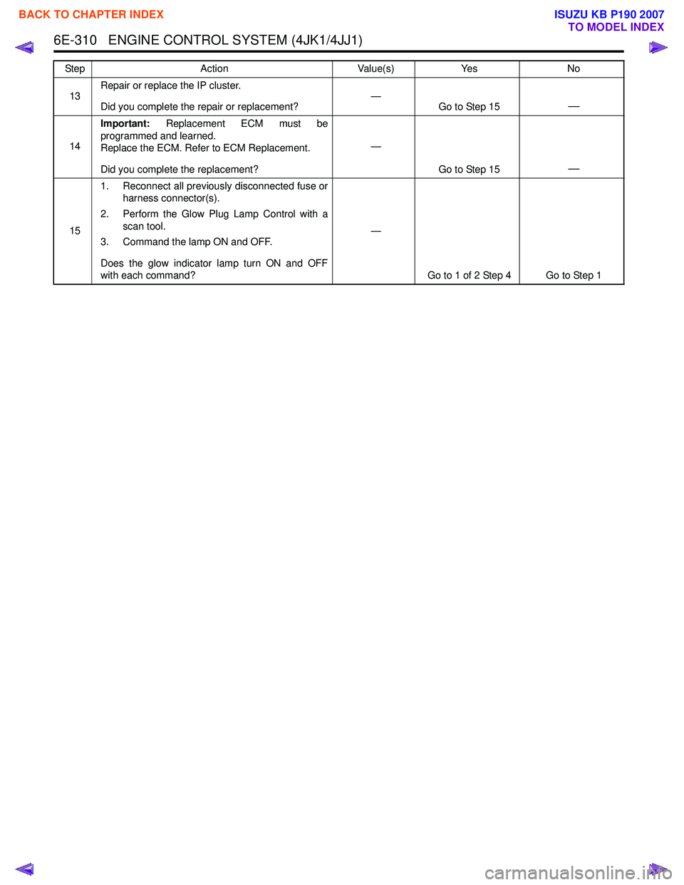
13Repair or replace the IP cluster.
Did you complete the repair or replacement? —
Go to Step 15—
14Important:
Replacement ECM must be
programmed and learned.
Replace the ECM. Refer to ECM Replacement.
Did you complete the replacement? —
Go to Step 15
—
151. Reconnect all previously disconnected fuse or
harness connector(s).
2. Perform the Glow Plug Lamp Control with a scan tool.
3. Command the lamp ON and OFF.
Does the glow indicator lamp turn ON and OFF
with each command? —
Go to 1 of 2 Step 4 Go to Step 1
Step
Action Value(s)Yes No
BACK TO CHAPTER INDEX
TO MODEL INDEX
ISUZU KB P190 2007
Page 1931 of 6020
6E-314 ENGINE CONTROL SYSTEM (4JK1/4JJ1)
Cruise Control System Check
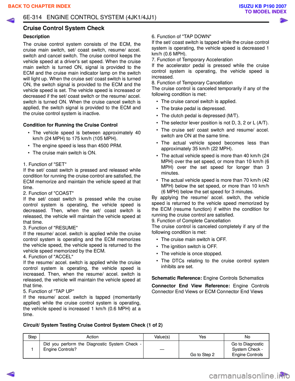
Description
The cruise control system consists of the ECM, the
cruise main switch, set/ coast switch, resume/ accel.
switch and cancel switch. The cruise control keeps the
vehicle speed at a driver's set speed. When the cruise
main switch is turned ON, signal is provided to the
ECM and the cruise main indicator lamp on the switch
will light up. When the cruise set/ coast switch is turned
ON, the switch signal is provided to the ECM and the
vehicle speed is set. The vehicle speed is increased or
decreased if the set/ coast switch or the resume/ accel.
switch is turned ON. When the cruise cancel switch is
applied, the switch signal is provided to the ECM and
the cruise control system is inactive.
Condition for Running the Cruise Control • The vehicle speed is between approximately 40 km/h (24 MPH) to 175 km/h (105 MPH).
• The engine speed is less than 4500 PRM.
• The cruise main switch is ON.
1. Function of "SET"
If the set/ coast switch is pressed and released while
condition for running the cruise control are satisfied, the
ECM memorize and maintain the vehicle speed at that
time.
2. Function of "COAST"
If the set/ coast switch is pressed while the cruise
control system is operating, the vehicle speed is
decreased. Then, when the set/ coast switch is
released, the vehicle will maintain the vehicle speed at
that time.
3. Function of "RESUME"
If the resume/ accel. switch is applied while the cruise
control system is operating and the ECM memorizes
the vehicle speed, the vehicle speed is returned to the
vehicle speed memorized by the ECM.
4. Function of "ACCEL"
If the resume/ accel. switch is applied while the cruise
control system is operating, the vehicle speed is
increased. Then, when the resume/ accel. switch is
released, the vehicle will maintain the vehicle speed at
that time.
5. Function of "TAP UP"
If the resume/ accel. switch is tapped (momentarily
applied) while the cruise control system is operating,
the vehicle speed is increased 1 km/h (0.6 MPH) at a
time. 6. Function of "TAP DOWN"
If the set/ coast switch is tapped while the cruise control
system is operating, the vehicle speed is decreased 1
km/h (0.6 MPH).
7. Function of Temporary Acceleration
If the accelerator pedal is pressed while the cruise
control system is operating, the vehicle speed is
increased.
8. Function of Temporary Cancellation
The cruise control is canceled temporarily if any of the
following condition is met:
• The cruise cancel switch is applied.
• The brake pedal is depressed.
• The clutch pedal is depressed (M/T).
• The selector lever position is not D, 3, 2 or L (A/T).
• The cruise set/ coast switch and resume/ accel. switch are ON at the same time.
• The actual vehicle speed becomes less than approximately 35 km/h (22 MPH).
• The actual vehicle speed is more than 40 km/h (24 MPH) over the set speed, or more than 10 km/h (6
MPH) over the set speed for longer than 3
minutes.
• The actual vehicle speed is more than 70 km/h (42 MPH) below the set speed, or more than 10 km/h
(6 MPH) below the set speed for 3 minutes.
By applying the resume/ accel. switch, the vehicle
speed is returned to the vehicle speed memorized by
the ECM (resume function) if within the condition for
running the cruise control are satisfied.
9. Function of Complete Cancellation
The cruise control is canceled completely if any of the
following condition is met:
• The cruise main switch is OFF.
• The ignition switch is OFF.
• The vehicle is once stopped.
• The DTCs relating to the cruise control system inhibits are set.
Schematic Reference: Engine Controls Schematics
Connector End View Reference: Engine Controls
Connector End Views or ECM Connector End Views
Circuit/ System Testing Cruise Control System Check (1 of 2)
Step Action Value(s)Yes No
1 Did you perform the Diagnostic System Check -
Engine Controls? —
Go to Step 2 Go to Diagnostic
System Check -
Engine Controls
BACK TO CHAPTER INDEX
TO MODEL INDEX
ISUZU KB P190 2007
Page 1940 of 6020
ENGINE CONTROL SYSTEM (4JK1/4JJ1) 6E-323
Symptoms - Engine Controls
Symptoms - Engine Controls
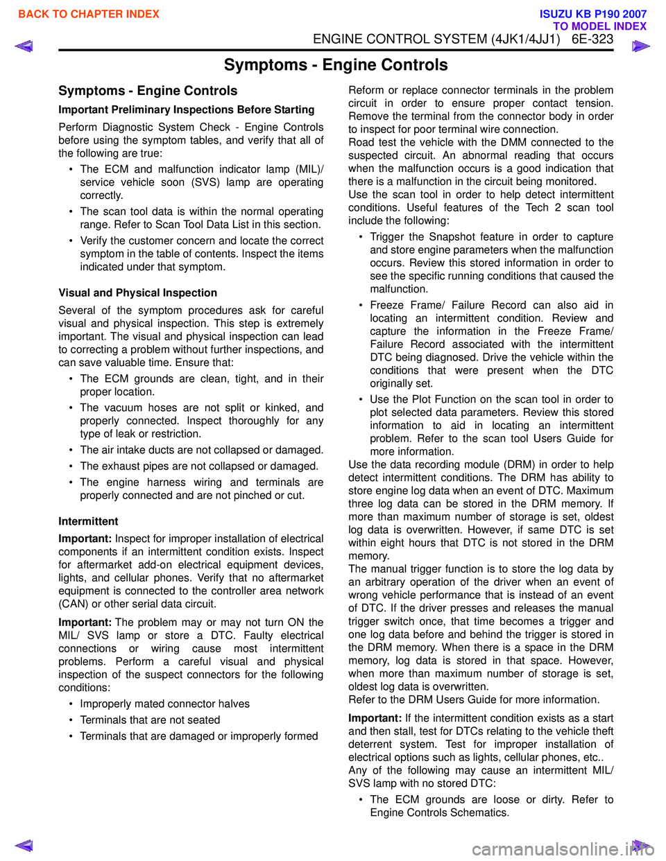
Important Preliminary Inspections Before Starting
Perform Diagnostic System Check - Engine Controls
before using the symptom tables, and verify that all of
the following are true:
• The ECM and malfunction indicator lamp (MIL)/ service vehicle soon (SVS) lamp are operating
correctly.
• The scan tool data is within the normal operating range. Refer to Scan Tool Data List in this section.
• Verify the customer concern and locate the correct symptom in the table of contents. Inspect the items
indicated under that symptom.
Visual and Physical Inspection
Several of the symptom procedures ask for careful
visual and physical inspection. This step is extremely
important. The visual and physical inspection can lead
to correcting a problem without further inspections, and
can save valuable time. Ensure that:
• The ECM grounds are clean, tight, and in their proper location.
• The vacuum hoses are not split or kinked, and properly connected. Inspect thoroughly for any
type of leak or restriction.
• The air intake ducts are not collapsed or damaged.
• The exhaust pipes are not collapsed or damaged.
• The engine harness wiring and terminals are properly connected and are not pinched or cut.
Intermittent
Important: Inspect for improper installation of electrical
components if an intermittent condition exists. Inspect
for aftermarket add-on electrical equipment devices,
lights, and cellular phones. Verify that no aftermarket
equipment is connected to the controller area network
(CAN) or other serial data circuit.
Important: The problem may or may not turn ON the
MIL/ SVS lamp or store a DTC. Faulty electrical
connections or wiring cause most intermittent
problems. Perform a careful visual and physical
inspection of the suspect connectors for the following
conditions:
• Improperly mated connector halves
• Terminals that are not seated
• Terminals that are damaged or improperly formed Reform or replace connector terminals in the problem
circuit in order to ensure proper contact tension.
Remove the terminal from the connector body in order
to inspect for poor terminal wire connection.
Road test the vehicle with the DMM connected to the
suspected circuit. An abnormal reading that occurs
when the malfunction occurs is a good indication that
there is a malfunction in the circuit being monitored.
Use the scan tool in order to help detect intermittent
conditions. Useful features of the Tech 2 scan tool
include the following:
• Trigger the Snapshot feature in order to capture and store engine parameters when the malfunction
occurs. Review this stored information in order to
see the specific running conditions that caused the
malfunction.
• Freeze Frame/ Failure Record can also aid in locating an intermittent condition. Review and
capture the information in the Freeze Frame/
Failure Record associated with the intermittent
DTC being diagnosed. Drive the vehicle within the
conditions that were present when the DTC
originally set.
• Use the Plot Function on the scan tool in order to plot selected data parameters. Review this stored
information to aid in locating an intermittent
problem. Refer to the scan tool Users Guide for
more information.
Use the data recording module (DRM) in order to help
detect intermittent conditions. The DRM has ability to
store engine log data when an event of DTC. Maximum
three log data can be stored in the DRM memory. If
more than maximum number of storage is set, oldest
log data is overwritten. However, if same DTC is set
within eight hours that DTC is not stored in the DRM
memory.
The manual trigger function is to store the log data by
an arbitrary operation of the driver when an event of
wrong vehicle performance that is instead of an event
of DTC. If the driver presses and releases the manual
trigger switch once, that time becomes a trigger and
one log data before and behind the trigger is stored in
the DRM memory. When there is a space in the DRM
memory, log data is stored in that space. However,
when more than maximum number of storage is set,
oldest log data is overwritten.
Refer to the DRM Users Guide for more information.
Important: If the intermittent condition exists as a start
and then stall, test for DTCs relating to the vehicle theft
deterrent system. Test for improper installation of
electrical options such as lights, cellular phones, etc..
Any of the following may cause an intermittent MIL/
SVS lamp with no stored DTC:
• The ECM grounds are loose or dirty. Refer to Engine Controls Schematics.
BACK TO CHAPTER INDEX
TO MODEL INDEX
ISUZU KB P190 2007