2007 ISUZU KB P190 indicator
[x] Cancel search: indicatorPage 2984 of 6020
Engine Mechanical – V6 Page 6A1–207
Page 6A1–207
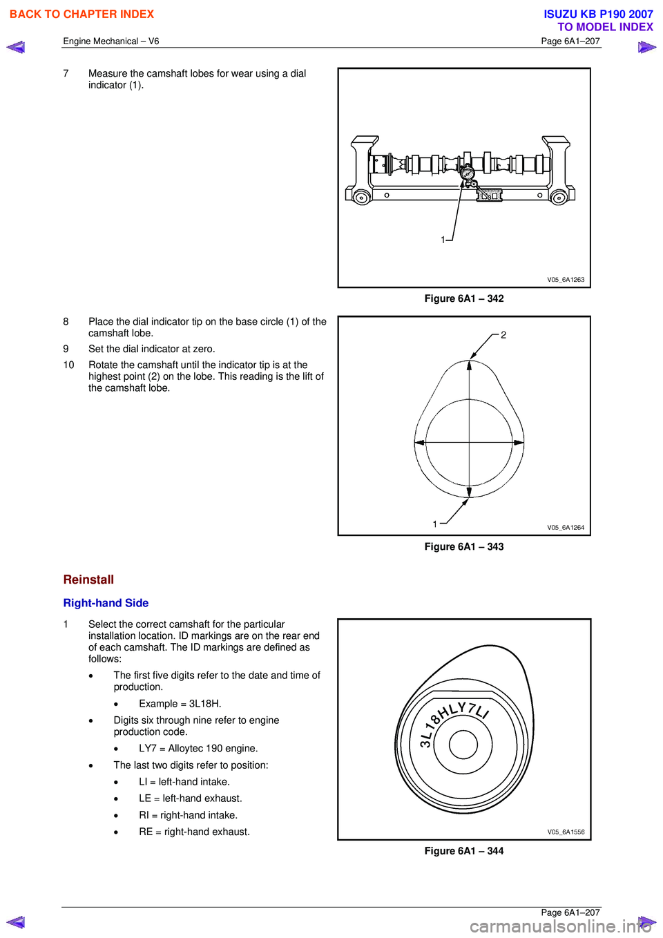
7 Measure the camshaft lobes for wear using a dial
indicator (1).
Figure 6A1 – 342
8 Place the dial indicator tip on the base circle (1) of the camshaft lobe.
9 Set the dial indicator at zero.
10 Rotate the camshaft until the indicator tip is at the highest point (2) on the lobe. This reading is the lift of
the camshaft lobe.
Figure 6A1 – 343
Reinstall
Right-hand Side
1 Select the correct camshaft for the particular installation location. ID markings are on the rear end
of each camshaft. The ID markings are defined as
follows:
• The first five digits refer to the date and time of
production.
• Example = 3L18H.
• Digits six through nine refer to engine
production code.
• LY7 = Alloytec 190 engine.
• The last two digits refer to position:
• LI = left-hand intake.
• LE = left-hand exhaust.
• RI = right-hand intake.
• RE = right-hand exhaust.
Figure 6A1 – 344
BACK TO CHAPTER INDEX
TO MODEL INDEX
ISUZU KB P190 2007
Page 3001 of 6020
Engine Mechanical – V6 Page 6A1–224
Page 6A1–224
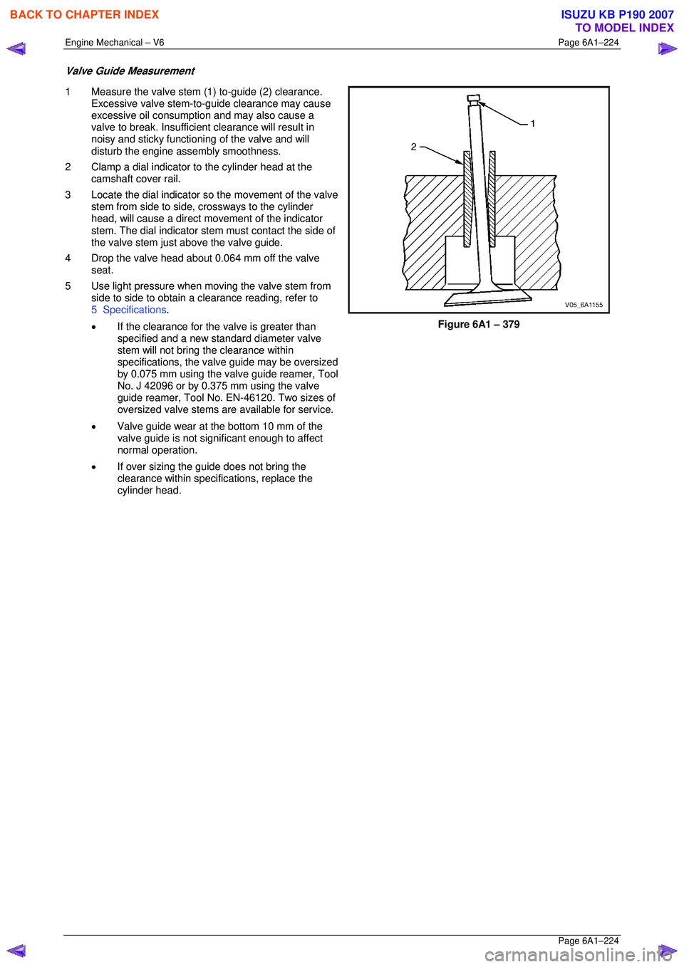
Valve Guide Measurement
1 Measure the valve stem (1) to-guide (2) clearance.
Excessive valve stem-to-guide clearance may cause
excessive oil consumption and may also cause a
valve to break. Insufficient clearance will result in
noisy and sticky functioning of the valve and will
disturb the engine assembly smoothness.
2 Clamp a dial indicator to the cylinder head at the camshaft cover rail.
3 Locate the dial indicator so the movement of the valve
stem from side to side, crossways to the cylinder
head, will cause a direct mo vement of the indicator
stem. The dial indicator stem must contact the side of
the valve stem just above the valve guide.
4 Drop the valve head about 0.064 mm off the valve seat.
5 Use light pressure when moving the valve stem from side to side to obtain a clearance reading, refer to
5 Specifications .
• If the clearance for the valve is greater than
specified and a new st andard diameter valve
stem will not bring the clearance within
specifications, the valv e guide may be oversized
by 0.075 mm using the valve guide reamer, Tool
No. J 42096 or by 0.375 mm using the valve
guide reamer, Tool No. EN-46120. Two sizes of
oversized valve stems are available for service.
• Valve guide wear at the bottom 10 mm of the
valve guide is not significant enough to affect
normal operation.
• If over sizing the guide does not bring the
clearance within specif ications, replace the
cylinder head.
Figure 6A1 – 379
BACK TO CHAPTER INDEX
TO MODEL INDEX
ISUZU KB P190 2007
Page 3004 of 6020
Engine Mechanical – V6 Page 6A1–227
Page 6A1–227
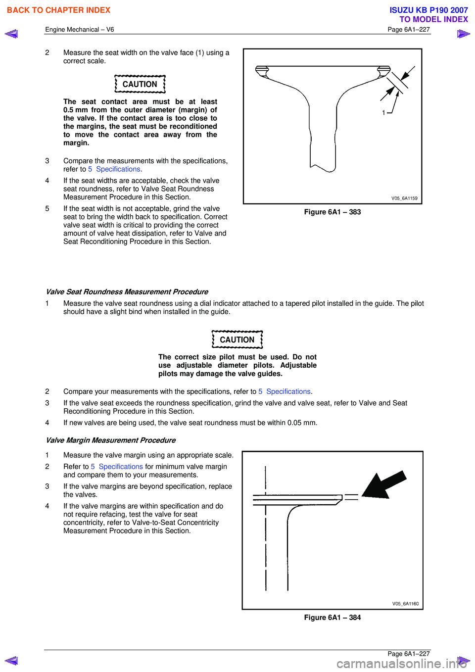
2 Measure the seat width on the valve face (1) using a
correct scale.
CAUTION
The seat contact area must be at least
0.5 mm from the outer diameter (margin) of
the valve. If the contact area is too close to
the margins, the seat must be reconditioned
to move the contact area away from the
margin.
3 Compare the measurements with the specifications,
refer to 5 Specifications .
4 If the seat widths are a cceptable, check the valve
seat roundness, refer to Valve Seat Roundness
Measurement Procedure in this Section.
5 If the seat width is not acceptable, grind the valve
seat to bring the width back to specification. Correct
valve seat width is critical to providing the correct
amount of valve heat dissipat ion, refer to Valve and
Seat Reconditioning Procedure in this Section.
Figure 6A1 – 383
Valve Seat Roundness Measurement Procedure
1 Measure the valve seat roundness using a dial indicator a ttached to a tapered pilot installed in the guide. The pilot
should have a slight bind w hen installed in the guide.
CAUTION
The correct size pilot must be used. Do not
use adjustable diameter pilots. Adjustable
pilots may damage the valve guides.
2 Compare your measurements with the specifications, refer to 5 Specifications.
3 If the valve seat exceeds the roundne ss specification, grind the valve and valve seat, refer to Valve and Seat
Reconditioning Procedure in this Section.
4 If new valves are being used, the valv e seat roundness must be within 0.05 mm.
Valve Margin Measurement Procedure
1 Measure the valve margin using an appropriate scale.
2 Refer to 5 Specifications for minimum valve margin
and compare them to your measurements.
3 If the valve margins are beyond specification, replace the valves.
4 If the valve margins are within specification and do not require refacing, test the valve for seat
concentricity, refer to Valve-to-Seat Concentricity
Measurement Procedure in this Section.
Figure 6A1 – 384
BACK TO CHAPTER INDEX
TO MODEL INDEX
ISUZU KB P190 2007
Page 3022 of 6020
Engine Mechanical – V6 Page 6A1–245
Page 6A1–245
35 Disconnect the harness connector from the transmission, refer to Section 7B1 Manual Transmission – V6 or
Section 7C1, Section 7C2, Section 7C3 or Section 7C4 for automatic transmission.
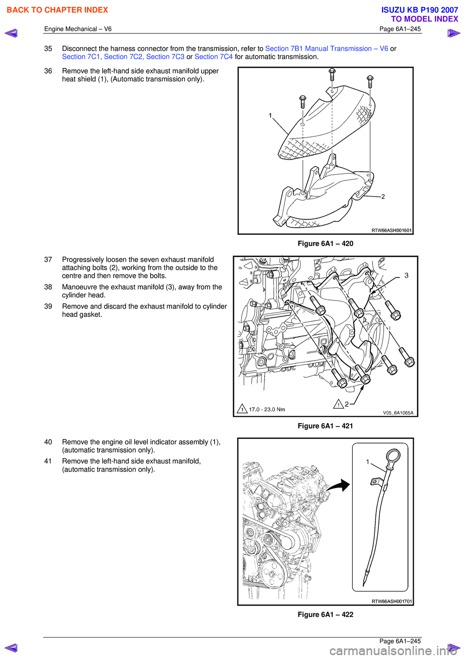
36 Remove the left-hand side exhaust manifold upper heat shield (1), (Automatic transmission only).
Figure 6A1 – 420
37 Progressively loosen the seven exhaust manifold attaching bolts (2), working from the outside to the
centre and then remove the bolts.
38 Manoeuvre the exhaust manifold (3), away from the cylinder head.
39 Remove and discard the exhaust manifold to cylinder head gasket.
Figure 6A1 – 421
40 Remove the engine oil level indicator assembly (1), (automatic transmission only).
41 Remove the left-hand side exhaust manifold, (automatic transmission only).
Figure 6A1 – 422
BACK TO CHAPTER INDEX
TO MODEL INDEX
ISUZU KB P190 2007
Page 3058 of 6020

Engine Mechanical – V6 Page 6A1–281
Page 6A1–281
4.6 Crankshaft and Main Bearings
1 Remove the engine assembly, refer to 4.1 Engine .
2 Remove both cylinder head assemblies, refer to 3.22 Cylinder Head Assembly.
3 Remove the oil pan assembly, refer to 4.2 Oil Pan and Oil Pump Suction Pipe Assembly .
4 Remove the piston and connecting rod assemblies, refer to 4.5 Pistons, Pins, Rings, Connecting Rods and Big-
end Bearings .
5 Remove the oil pump assembly, refer to 3.17 Oil Pump Assembly.
6 Remove the crankshaft rear oil seal and plate assembly, refer to 4.4 Crankshaft Rear Seal and Plate Assembly .
7 Remove the crankshaft position sensor, refer to Section 6C1-3 Engine Management – V6 – Service Operations.
Crankshaft End Play Measurement
1 Place a dial indicator at the end of the crankshaft nose.
2 Gently force the crankshaft towards the front and rear of the cylinder block with a lever while monitoring the
movement of the dial indicator.
3 The crankshaft endplay should not exceed specifications, refer to 5 Specifications.
4 If the specifications are ex ceeded, inspect the thrust bearing thrust outer diameter and the crankshaft thrust wall for
wear and/or excessive runout. Compare the va lues with the specifications, refer to 5 Specifications.
5 Replace the thrust bearing or crankshaft as required.
Remove
1 Remove the crankshaft bearing cap side bolts (3).
CAUTION
The crankshaft bearing cap outer bolts are
yield tightened during assembly and must
be replaced prior to reassembly. Crankshaft
bearing cap outer bolts that are not replaced
will not torque to the correct clamp load and
can lead to serious engine damage.
2 Remove the crankshaft bearing cap outer bolts (1).
3 Remove the crankshaft bearing cap inner bolts (2).
Figure 6A1 – 500
BACK TO CHAPTER INDEX
TO MODEL INDEX
ISUZU KB P190 2007
Page 3063 of 6020
Engine Mechanical – V6 Page 6A1–286
Page 6A1–286
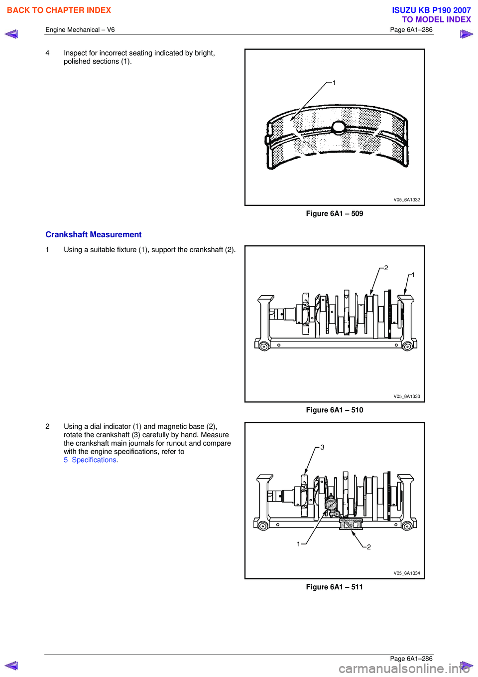
4 Inspect for incorrect seating indicated by bright,
polished sections (1).
Figure 6A1 – 509
Crankshaft Measurement
1 Using a suitable fixture (1 ), support the crankshaft (2).
Figure 6A1 – 510
2 Using a dial indicator (1) and magnetic base (2), rotate the crankshaft (3) carefully by hand. Measure
the crankshaft main journals for runout and compare
with the engine specifications, refer to
5 Specifications .
Figure 6A1 – 511
BACK TO CHAPTER INDEX
TO MODEL INDEX
ISUZU KB P190 2007
Page 3128 of 6020
Engine Mechanical – V6 Page 6A1–351
Page 6A1–351
6 Torque Wrench Specifications
ATTENTION
�„ Fasteners must be replaced after loosening.
Fasteners either have micro encapsulated sealant a pplied or incorporate a mechanical thread lock and
should only be re-used once. If in doubt, replacement is recommended.
Oil Pan Drain Plug ................................................................................ 25.0 Nm
Oil Filter Adaptor Attach ing Bolt................................................ 20.0 – 26.0 Nm
Oil Level Indicator Tube Atta ching Bolt........................................ 8.0 – 12.0 Nm
Accessory Drive Belt Idler Pu lley Attaching Bolt................................... 50.0 Nm
Accessory Drive Belt Tensio ner Attaching Bolt .................................... 50.0 Nm
Power Steering Reserv oir Bracket Attaching Screw.............................. 9.0 Nm
Power Steering Pump Bracket A ttaching Bolt ........................... 49. 0 – 67.0 Nm
Upper Intake Manifold to Lower Intake Manifold Attaching Bolt ........... 23.0 Nm
Upper Intake Manifold to Cylinder Head Attaching Bolt........................ 23.0 Nm
Lower Intake Manifold to Cylind er Head Attaching Bolt........................ 23.0 Nm
Fuel Injector Wiring Harness Br acket Attaching bolt .............................. 9. 0 Nm
Exhaust Manifold to Cylinder He ad Attaching Bolt..................... 17.0 - 23.0 Nm
Exhaust Manifold Heat Shield Attaching Bolt ............................... 8.0 - 12.0 Nm
Battery Harness Ground Terminal Attaching Nut ................................. 13. 0 Nm
Camshaft Cover Attachi ng Bolt................................................... 8.0 – 12.0 Nm
Engine Ground Connec tor Bolt............................................................. 10.0 Nm
Engine Wiring Harness Former A ttaching Bolt .......................... 12.0 – 16.0 Nm
�„ Crankshaft Balancer A ssembly Attaching Bolt:
Stage 1 ..................................................................................... 90.0 –110.0 Nm
Stage 2 ....................................................................................................... 150 °
Engine Front Cover Assembly A ttaching Bolt ............................ 20. 0 – 26.0 Nm
Camshaft Intermediate Sprocket Attaching Bolt ........................ 58. 0 – 72.0 Nm
Secondary Timing Chai n Guide Attaching Bolt.......................... 20.0 – 26.0 Nm
Secondary Timing Chai n Shoe Attaching Bolt ........................... 20.0 – 26.0 Nm
Secondary Timing Chain Tensioner Attachi ng Bolt ................... 20.0 – 26.0 Nm
Primary Timing Chain Upper Gui de Attaching Bolt.................... 20.0 – 26.0 Nm
Primary Timing Chain Tensioner Attaching Bolt........................ 20. 0 – 26.0 Nm
Oil Pump Assembly Attach ing Bolt............................................ 20.0 – 26.0 Nm
Camshaft Sprocket Attachi ng Bolt............................................. 49.0 – 67.0 Nm
Exhaust Camshaft Sprocket Atta ching Bolt............................... 49.0 – 67.0 Nm
Camshaft Bearing Cap Attach ing Bolt......................................... 8.0 – 12.0 Nm
Cylinder Head Thr eaded Plug.............................................................. 31.0 Nm
�„ Cylinder Head M11 Attaching Bolt:
Stage 1 ...................................................................................... 40.0 – 50.0 Nm
Stage 2 ....................................................................................................... 120 °
�„ Cylinder Head M8 Attaching Bolt:
Stage 1 ...................................................................................... 12.0 – 18.0 Nm
Stage 2 ......................................................................................................... 60 °
Engine Mount Bracket to Cylinder Bl ock Attaching Bolt............ 43.0 – 57.0 Nm
Engine Mount to Bracket Atta ching Nut..................................... 70.0 – 90.0 Nm
Engine Mount to Frame Atta ching Nut...................................... 44.0 – 60.0 Nm
Engine Lift Bracket Attachi ng Bolt.......................................... 58.0 – 72.0.0 Nm
Knock Sensor Attach ing Nut................................................................. 23.0 Nm
BACK TO CHAPTER INDEX
TO MODEL INDEX
ISUZU KB P190 2007
Page 3149 of 6020
Engine Cooling – V6 Engine Page 6B1–14
2.7 Coolant Recovery Reservoir
The coolant is maintained at the ideal level in the radiator by the coolant filler cap and the coolant recovery reservoir,
resulting in increased cooling efficiency.
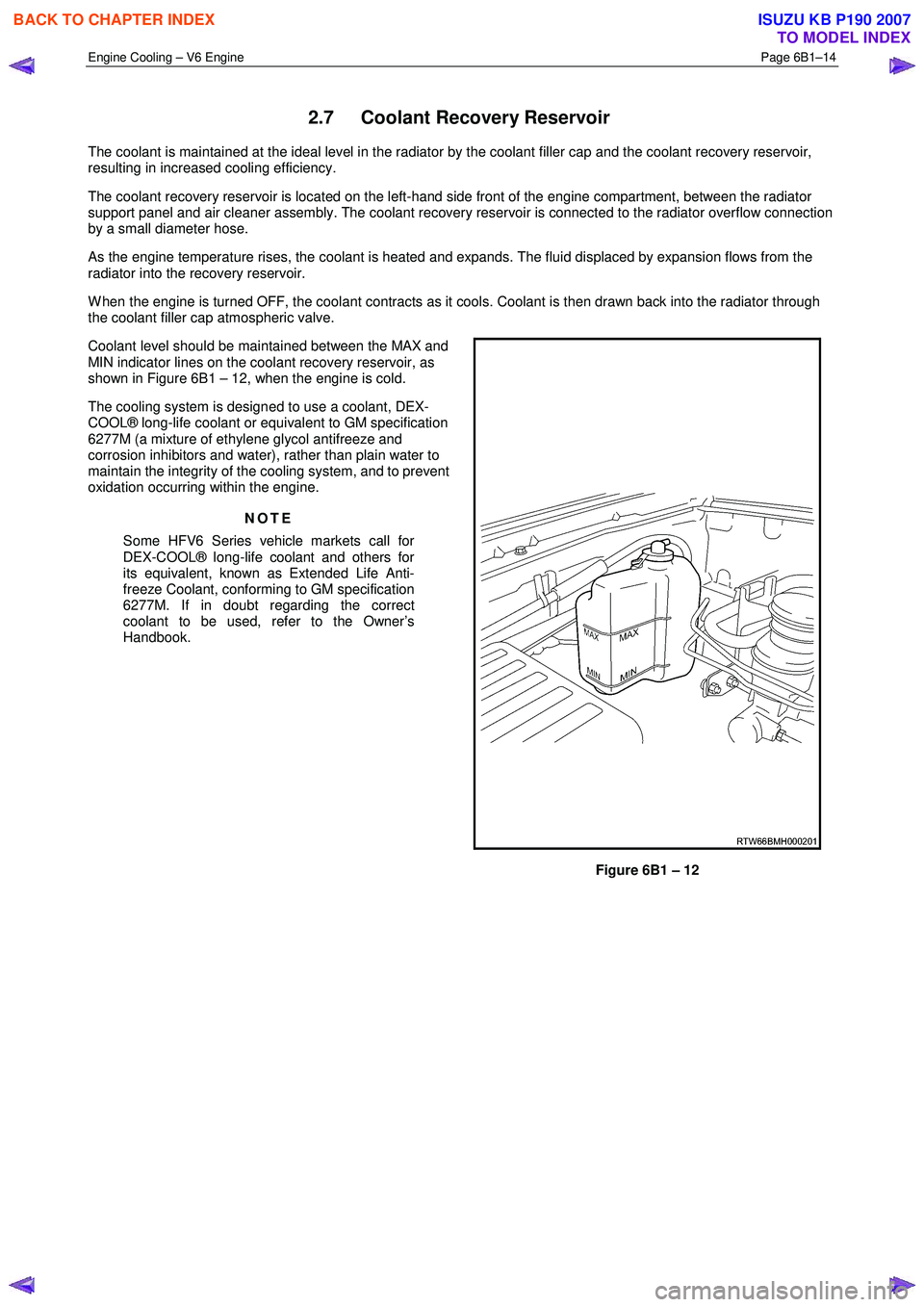
The coolant recovery reservoir is located on the left-hand side front of the engine compartment, between the radiator
support panel and air cleaner assembly. The coolant recovery reservoir is connected to the radiator overflow connection
by a small diameter hose.
As the engine temperature rises, the coolant is heated and expands. The fluid displaced by expansion flows from the
radiator into the recovery reservoir.
W hen the engine is turned OFF, the coolant contracts as it cools. Coolant is then drawn back into the radiator through
the coolant filler cap atmospheric valve.
Coolant level should be maintained between the MAX and
MIN indicator lines on the coolant recovery reservoir, as
shown in Figure 6B1 – 12, when the engine is cold.
The cooling system is designed to use a coolant, DEX-
COOL® long-life coolant or equivalent to GM specification
6277M (a mixture of ethylene glycol antifreeze and
corrosion inhibitors and water), rather than plain water to
maintain the integrity of the cooling system, and to prevent
oxidation occurring within the engine.
NOTE
Some HFV6 Series vehicle markets call for
DEX-COOL® long-life coolant and others for
its equivalent, known as Extended Life Anti-
freeze Coolant, conforming to GM specification
6277M. If in doubt regarding the correct
coolant to be used, refer to the Owner’s
Handbook.
Figure 6B1 – 12
BACK TO CHAPTER INDEX
TO MODEL INDEX
ISUZU KB P190 2007