2007 ISUZU KB P190 Electrical
[x] Cancel search: ElectricalPage 3189 of 6020
Engine Cooling – V6 Engine Page 6B1–54
3.15 Radiator
Remove
Refer to 3.1 Service Notes in this Section, for
important safety items.
1 Allow engine to cool to ambient temperature (less than 50 ° C), then remove coolant filler cap.
Disconnection of the battery affects certain
vehicle electronic systems. Refer to 00
Warnings, Cautions and Notes, before
removing the ground lead.
2 Disconnect the battery ground lead. Refer to 8A – Electrical Body & Chassis.
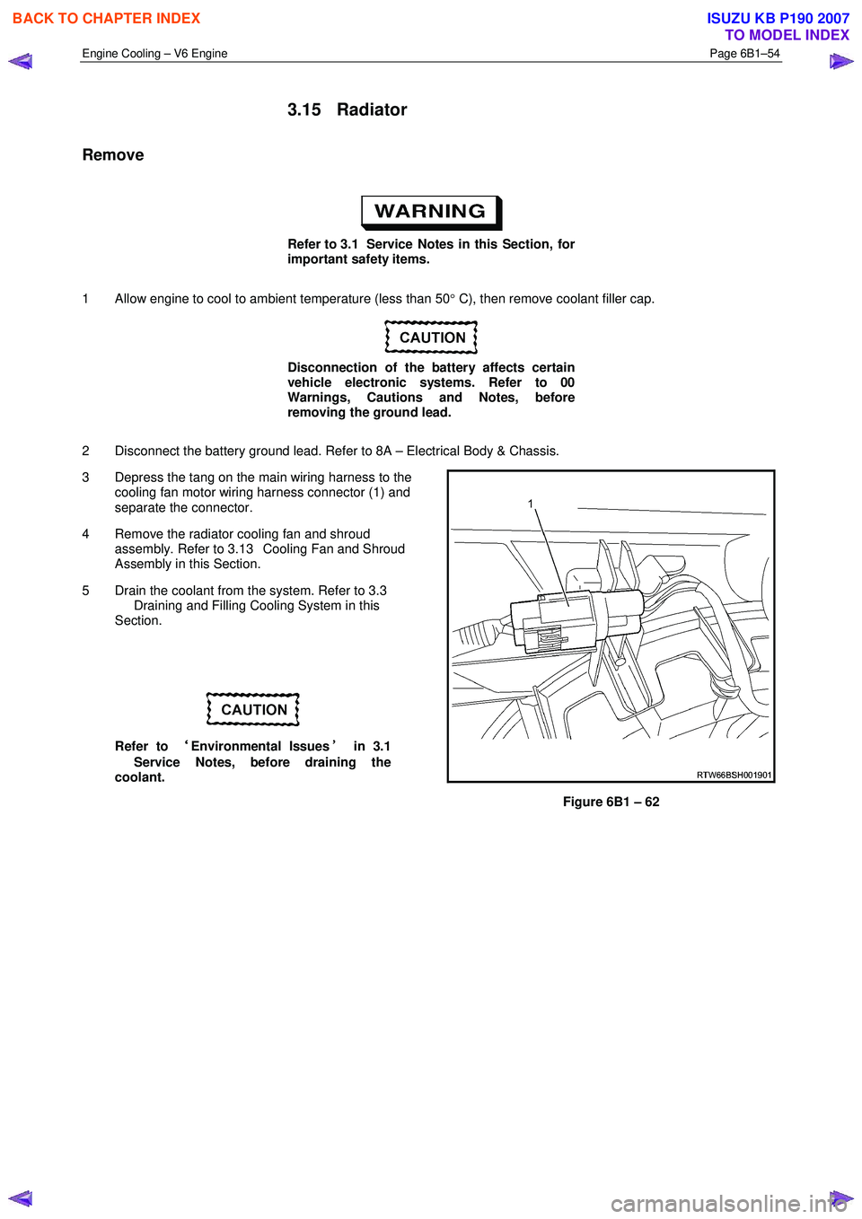
3 Depress the tang on the main wiring harness to the cooling fan motor wiring harness connector (1) and
separate the connector.
4 Remove the radiator cooling fan and shroud assembly. Refer to 3.13 Cooling Fan and Shroud
Assembly in this Section.
5 Drain the coolant from the system. Refer to 3.3 Draining and Filling Cooling System in this
Section.
Refer to ‘
‘‘
‘
Environmental Issues ’
’’
’
in 3.1
Service Notes, before draining the
coolant.
Figure 6B1 – 62
BACK TO CHAPTER INDEX
TO MODEL INDEX
ISUZU KB P190 2007
Page 3191 of 6020
Engine Cooling – V6 Engine Page 6B1–56
Reinstall
Installation of the radiator is the reverse of removal procedures, noting the following points:
1 Before installing radiator, inspect core to ensure that there is no foreign matter in core fins. Clean out between core fins with compressed air, blowing from rear to front.
2 If the vehicle is fitted with an automatic transmission, remove plugs from the removed cooling pipe ends and the two quick connect fittings.
3 After wiping cooler line ends and smearing clean automatic transmission fluid over each flared line end, push into the quick connect fitting to engage. As a security check, tug on each line to ensure correct engagement.
4 Check the transmission fluid level. Refer to the following references as required:
• 7C4 Automatic Transmission
• 4L60E On-vehicle Servicing
5 Install the following hoses:
a. Lower radiator hose, securing with the hose clamp.
b. Upper radiator hose, securing with the hose clamp.
6 Install the radiator cooling fan and shroud assembly. Refer to 3.13Cooling Fan and Shroud Assembly in this Section. Ensure that electrical connectors and the transmission cooler lines are seated correctly in the integral
retainer clips before install upper radiator shroud.
7 Refill cooling system. Refer to 3.3 Draining and Filling Cooling System in this Section.
8 Check for coolant leaks. Refer to 3.7 Pressure Testing in this Section.
9 Reconnect battery ground lead. Refer to 8A Electrical Body & Chassis.
10 Check cooling fan operation. Refer to 6C1-2 Engine Management Diagnostics. Also check for correct rotational direction of cooling fan.
BACK TO CHAPTER INDEX
TO MODEL INDEX
ISUZU KB P190 2007
Page 3209 of 6020
Fuel System – V6 Page 6C – 7
Fuel Flow
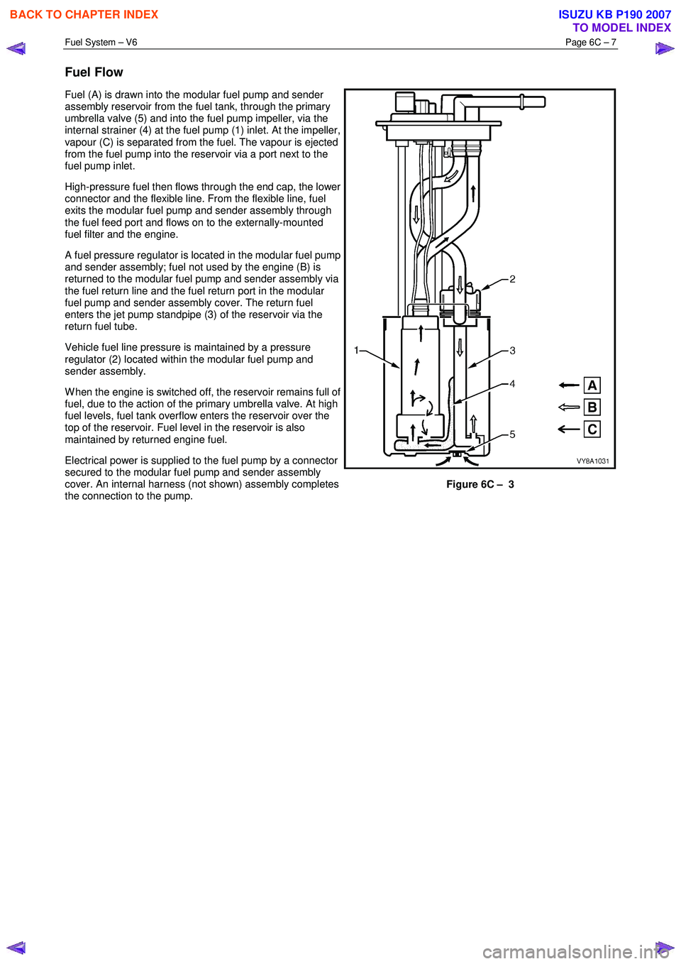
Fuel (A) is drawn into the modular fuel pump and sender
assembly reservoir from the fuel tank, through the primary
umbrella valve (5) and into the fuel pump impeller, via the
internal strainer (4) at the fuel pump (1) inlet. At the impeller,
vapour (C) is separated from the fuel. The vapour is ejected
from the fuel pump into the reservoir via a port next to the
fuel pump inlet.
High-pressure fuel then flows through the end cap, the lower
connector and the flexible line. From the flexible line, fuel
exits the modular fuel pump and sender assembly through
the fuel feed port and flows on to the externally-mounted
fuel filter and the engine.
A fuel pressure regulator is located in the modular fuel pump
and sender assembly; fuel not used by the engine (B) is
returned to the modular fuel pump and sender assembly via
the fuel return line and the fuel return port in the modular
fuel pump and sender assembly cover. The return fuel
enters the jet pump standpipe (3) of the reservoir via the
return fuel tube.
Vehicle fuel line pressure is maintained by a pressure
regulator (2) located within the modular fuel pump and
sender assembly.
W hen the engine is switched off, the reservoir remains full of
fuel, due to the action of the primary umbrella valve. At high
fuel levels, fuel tank overflow enters the reservoir over the
top of the reservoir. Fuel level in the reservoir is also
maintained by returned engine fuel.
Electrical power is supplied to the fuel pump by a connector
secured to the modular fuel pump and sender assembly
cover. An internal harness (not shown) assembly completes
the connection to the pump.
Figure 6C – 3
BACK TO CHAPTER INDEX
TO MODEL INDEX
ISUZU KB P190 2007
Page 3213 of 6020
Fuel System – V6 Page 6C – 11
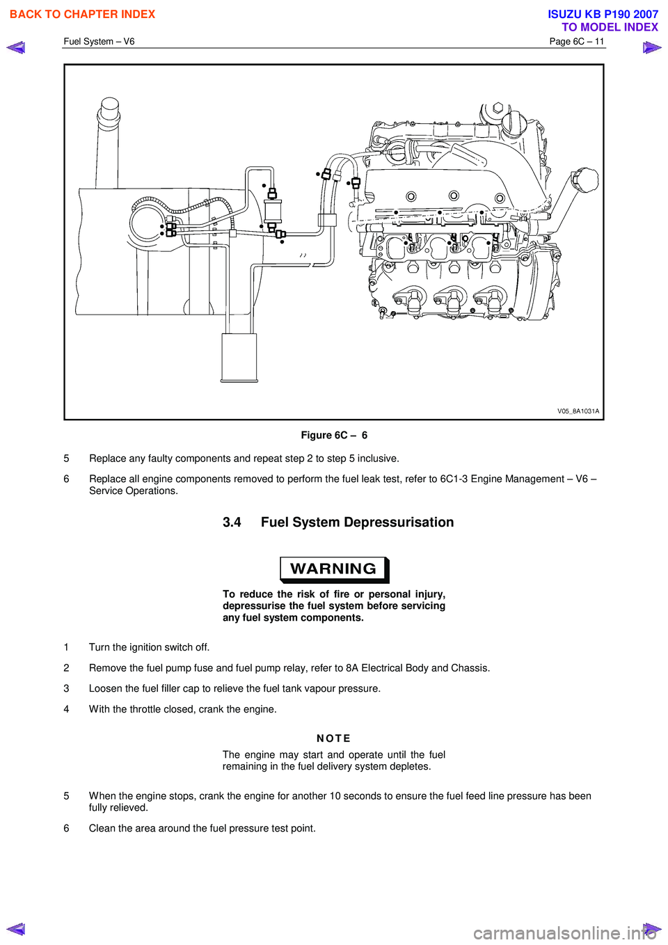
Figure 6C – 6
5 Replace any faulty components and repeat step 2 to step 5 inclusive.
6 Replace all engine components removed to perform the fuel leak test, refer to 6C1-3 Engine Management – V6 – Service Operations.
3.4 Fuel System Depressurisation
To reduce the risk of fire or personal injury,
depressurise the fuel system before servicing
any fuel system components.
1 Turn the ignition switch off.
2 Remove the fuel pump fuse and fuel pump relay, refer to 8A Electrical Body and Chassis.
3 Loosen the fuel filler cap to relieve the fuel tank vapour pressure.
4 W ith the throttle closed, crank the engine.
NOTE
The engine may start and operate until the fuel
remaining in the fuel delivery system depletes.
5 W hen the engine stops, crank the engine for another 10 seconds to ensure the fuel feed line pressure has been fully relieved.
6 Clean the area around the fuel pressure test point.
BACK TO CHAPTER INDEX
TO MODEL INDEX
ISUZU KB P190 2007
Page 3221 of 6020
Fuel System – V6 Page 6C – 19
Remove
• A depressurised fuel system contains fuel
in the fuel filter and fuel lines that can be
spilled during service operations.
• Fuel vapour remains in the fuel tank even
when completely empty. Seal all openings
in the fuel tank using suitable material or a
plastic plug. Ensure no naked flames or
other ignition sources are nearby. Ensure
all cellular phones (and transmission
devices that may cause any metal objects
to become unintentional receiving
antennas) are switched off.
• Place a dry chemical (Class B) fire
extinguisher nearby before performing any
on-vehicle service procedures. Failure to
follow these precautions may result in
personal injury.
1 Remove the fuel pump relay, refer to 8A Electrical Body and Chassis.
2 Depressurise the fuel system, refer to 3.4 Fuel System Depressurisation.
Never drain or store fuel into an open
container, due to the possibility of fire or
explosion.
3 Siphon the fuel tank, using commercially-available equipment.
Before proceeding, clean all traces of dirt and
other foreign material from the top of the fuel
tank, near the modular fuel pump and sender
assembly.
7 Place a drain tray under the fuel filter area.
Fuel can spill from the disconnected filter.
BACK TO CHAPTER INDEX
TO MODEL INDEX
ISUZU KB P190 2007
Page 3223 of 6020
Fuel System – V6 Page 6C – 21
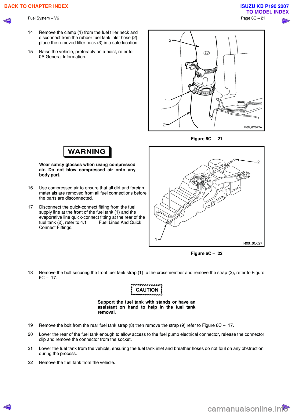
14 Remove the clamp (1) from the fuel filler neck and
disconnect from the rubber fuel tank inlet hose (2),
place the removed filler neck (3) in a safe location.
15 Raise the vehicle, preferably on a hoist, refer to 0A General Information.
Figure 6C – 21
Wear safety glasses when using compressed
air. Do not blow compressed air onto any
body part.
16 Use compressed air to ensure that all dirt and foreign materials are removed from all fuel connections before
the parts are disconnected.
17 Disconnect the quick-connect fitting from the fuel supply line at the front of the fuel tank (1) and the
evaporative line quick-connect fitting at the rear of the
fuel tank (2), refer to 4.1 Fuel Lines And Quick
Connect Fittings.
Figure 6C – 22
18 Remove the bolt securing the front fuel tank strap (1) to the crossmember and remove the strap (2), refer to Figure 6C – 17.
Support the fuel tank with stands or have an
assistant on hand to help in the fuel tank
removal.
19 Remove the bolt from the rear fuel tank strap (8) then remove the strap (9) refer to Figure 6C – 17.
20 Lower the rear of the fuel tank enough to allow access to the fuel pump electrical connector, release the connector clip and remove the connector from the socket.
21 Lower the fuel tank from the vehicle, ensuring the fuel tank inlet and breather hoses do not foul on any obstruction during the process.
22 Remove the fuel tank from the vehicle.
BACK TO CHAPTER INDEX
TO MODEL INDEX
ISUZU KB P190 2007
Page 3224 of 6020
Fuel System – V6 Page 6C – 22
Reinstall
Reinstallation of the fuel tank is the reverse of the removal procedure, noting the following:
1 Lift the fuel tank into position reinserting the fuel tank inlet and breather hoses into the body opening. Raise the fuel tank into place and rest the front of the tank on the crossmember.
2 Replace the fuel pump electrical connector, be sure to engage the locking tab.
3 Fit the fuel tank mounting straps in the following order, refer to Figure 6C – 17, a Loosely reattach the rear fuel tank mounting strap and bolt (8 & 9), refer to Figure 6C – 17.
b Loosely attach the front mounting strap and bolt (1 & 2), refer to Figure 6C – 17.
c Ensure that the fuel tank is located in the correct position then,
d Tighten the rear mounting strap bolt (8), Figure 6C – 17.
e Tighten the front mounting strap bolt (1), Figure 6C – 17.
4 Tighten all fuel tank mounting strap bolts to the correct torque specification.
Fuel tank mounting strap bolts
torque specification ............................................68.0 Nm
Install the fuel filter with the flow arrow on its
body pointing in the same direction as the
fuel flow to the front of the vehicle.
5 Install the disconnected quick-connect fittings to the fuel supply line at the front of the fuel tank and the evaporative line quick-connect fitting at the rear of the fuel tank. Refer to 4.1 Fuel Lines And Quick Connect Fittings, for the
correct component routeing.
6 Lower the vehicle to a comfortable working height and reinstall the clamp (1) to the fuel filler neck and reconnect the rubber fuel tank inlet hose (2) and tighten the clamp, refer to Figure 6C – 21.
7 Reinstall the fuel tank breather hose (3) to the fuel filler neck (1) and tighten the clamp (2), refer to Figure 6C – 20.
8 Clip the fuel filler door release cable (1) to the retainer on the fuel filler neck (2), refer to Figure 6C – 19.
9 Locate the fuel filler neck (3) to the filler pocket and attach with the securing screw (2), remove the cover material from the fuel filler neck inlet and refit the fuel filler cap (4), refer to Figure 6C – 18.
10 Reinstall the front half of the right-hand rear wheelhouse liner, refer to 10 Cab.
11 Before starting the vehicle, perform a fuel system leak test, refer to 3.3 Fuel Leak Test.
BACK TO CHAPTER INDEX
TO MODEL INDEX
ISUZU KB P190 2007
Page 3232 of 6020
Fuel System – V6 Page 6C – 30
4.7 Fuel Tank Siphon Procedure
• Fuel vapour remains in the modular fuel
pump and sender assembly and fuel lines
that can be spilled during service
operations. Ensure no naked flames or
other ignition sources are nearby. Ensure
all cellular phones (and transmission
devices that may cause any metal objects
to become unintentional receiving
antennas) are switched off.
• Place a dry chemical (Class B) fire
extinguisher nearby before performing any
on-vehicle service procedures. Failure to
follow these precautions may result in
personal injury.
For an exploded view of fuel tank components, refer Figure 6C – 17.
1 Depressurise the fuel system, refer to 3.4 Fuel System Depressurisation.
2 Reinstall the fuel pump relay, refer to 8A Electrical Body and Chassis.
Disconnecting the battery affects certain
vehicle electronic systems. 1.1 WARNING,
CAUTION and NOTES.
3 Disconnect the negative battery terminal.
4 Remove the fuel filler cap.
NOTE
Lubricate the fuel siphon hose with J36850
TransJel Transmission Assembly Lubricant or
equivalent to aid hose insertion. Use only an
approved lubricant.
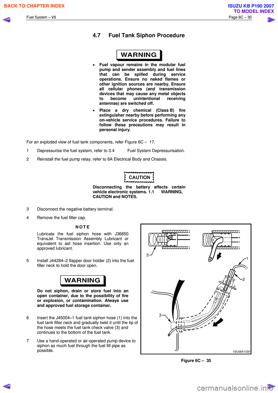
5 Install J44284–2 flapper door holder (2) into the fuel filler neck to hold the door open.
Do not siphon, drain or store fuel into an
open container, due to the possibility of fire
or explosion, or contamination. Always use
and approved fuel storage container.
6 Insert the J45004–1 fuel tank siphon hose (1) into the fuel tank filler neck and gradually twist it until the tip of
the hose meets the fuel tank check valve (3) and
continues to the bottom of the fuel tank.
7 Use a hand-operated or air-operated pump device to siphon as much fuel through the fuel fill pipe as
possible.
Figure 6C – 35
BACK TO CHAPTER INDEX
TO MODEL INDEX
ISUZU KB P190 2007