2007 ISUZU KB P190 Electrical
[x] Cancel search: ElectricalPage 3315 of 6020
Engine Management – V6 – Diagnostics Page 6C1-2–37
6 Functional Checks
6.1 General Information
The items detailed in the following pages are to be used when there is a customer complaint and there are no diagnostic
trouble codes set, or one or more of the Tech 2 data values are not within the typical values. They are also to be used
when instructed from a DTC table. Before using these tables, you should refer to 5 Symptoms Diagnostics in this
Section, which may direct you to using the following functional checks.
The purpose of these tables is to diagnose engine control module (ECM) controlled components or sub-systems that do
not have diagnostic trouble codes assigned to them. Another purpose of these tables is for Technicians who feel
confident that a particular part of the sub-system is not operating properly and wants only to check that particular item
for proper operation without going through lengthy diagnostic procedures.
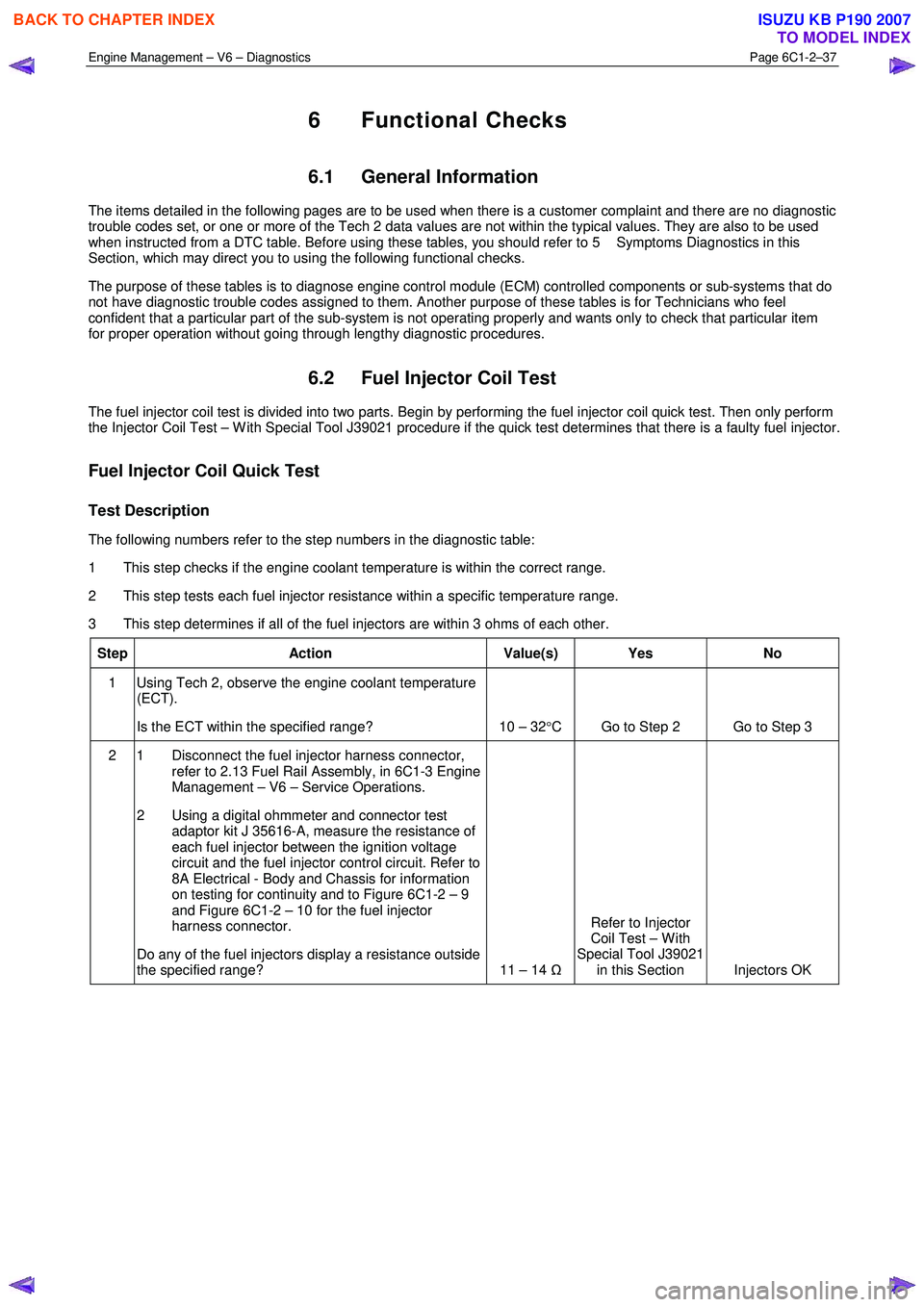
6.2 Fuel Injector Coil Test
The fuel injector coil test is divided into two parts. Begin by performing the fuel injector coil quick test. Then only perform
the Injector Coil Test – W ith Special Tool J39021 procedure if the quick test determines that there is a faulty fuel injector.
Fuel Injector Coil Quick Test
Test Description
The following numbers refer to the step numbers in the diagnostic table:
1 This step checks if the engine coolant temperature is within the correct range.
2 This step tests each fuel injector resistance within a specific temperature range.
3 This step determines if all of the fuel injectors are within 3 ohms of each other.
Step Action Value(s) Yes No
1 Using Tech 2, observe the engine coolant temperature
(ECT).
Is the ECT within the specified range? 10 – 32 °C Go to Step 2 Go to Step 3
2 1 Disconnect the fuel injector harness connector,
refer to 2.13 Fuel Rail Assembly, in 6C1-3 Engine
Management – V6 – Service Operations.
2 Using a digital ohmmeter and connector test adaptor kit J 35616-A, measure the resistance of
each fuel injector between the ignition voltage
circuit and the fuel injector control circuit. Refer to
8A Electrical - Body and Chassis for information
on testing for continuity and to Figure 6C1-2 – 9
and Figure 6C1-2 – 10 for the fuel injector
harness connector.
Do any of the fuel injectors display a resistance outside
the specified range? 11 – 14 ΩRefer to Injector
Coil Test – W ith
Special Tool J39021 in this Section Injectors OK
BACK TO CHAPTER INDEX
TO MODEL INDEX
ISUZU KB P190 2007
Page 3316 of 6020
Engine Management – V6 – Diagnostics Page 6C1-2–38
Step Action Value(s) Yes No
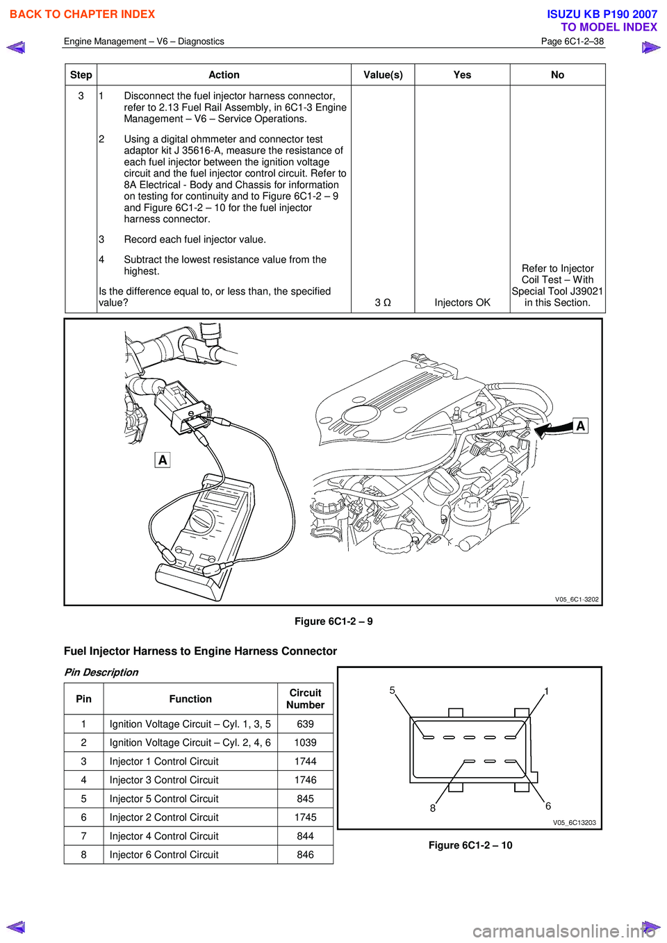
3 1 Disconnect the fuel injector harness connector,
refer to 2.13 Fuel Rail Assembly, in 6C1-3 Engine
Management – V6 – Service Operations.
2 Using a digital ohmmeter and connector test adaptor kit J 35616-A, measure the resistance of
each fuel injector between the ignition voltage
circuit and the fuel injector control circuit. Refer to
8A Electrical - Body and Chassis for information
on testing for continuity and to Figure 6C1-2 – 9
and Figure 6C1-2 – 10 for the fuel injector
harness connector.
3 Record each fuel injector value.
4 Subtract the lowest resistance value from the highest.
Is the difference equal to, or less than, the specified
value? 3
Ω
Injectors OK Refer to Injector
Coil Test – W ith
Special Tool J39021 in this Section.
Figure 6C1-2 – 9
Fuel Injector Harness to Engine Harness Connector
Pin Description
Pin Function Circuit
Number
1 Ignition Voltage Circuit – Cyl. 1, 3, 5 639
2 Ignition Voltage Circuit – Cyl. 2, 4, 6 1039
3 Injector 1 Control Circuit 1744
4 Injector 3 Control Circuit 1746
5 Injector 5 Control Circuit 845
6 Injector 2 Control Circuit 1745
7 Injector 4 Control Circuit 844
8 Injector 6 Control Circuit 846
Figure 6C1-2 – 10
BACK TO CHAPTER INDEX
TO MODEL INDEX
ISUZU KB P190 2007
Page 3326 of 6020
Engine Management – V6 – Diagnostics Page 6C1-2–48
Additional Information
• Use the J 35616-B Connector Test Adapter Kit for any test that requires probing the ECM harness connector or a
component harness connector.
• Inspect the ignition coils for aftermarket devices. An aftermarket device connected to the ignition coil circuits, may
cause a condition with the ignition coils.
• For an intermittent fault condition, refer to 5.2 Intermittent Fault Conditions in this Section.
• To assist diagnosis, refer to 3 W iring Diagrams and Connector Charts in this Section, for the system wiring
diagram and connector charts.
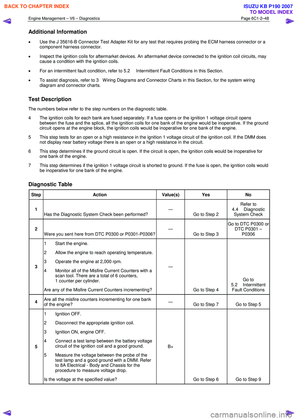
Test Description
The numbers below refer to the step numbers on the diagnostic table.
4 The ignition coils for each bank are fused separately. If a fuse opens or the ignition 1 voltage circuit opens between the fuse and the splice, all the ignition coils for one bank of the engine would be inoperative. If the ground
circuit opens at the engine block, the ignition coils would be inoperative for one bank of the engine.
5 This step tests for an open or a high resistance in the ignition 1 voltage circuit of the ignition coil. If the DMM does not display near battery voltage there is an open or a high resistance in the circuit.
6 This step determines if the ground circuit is open. If the circuit is open, the ignition coils would be inoperative for one bank of the engine.
7 This step determines if the ignition 1 voltage circuit is shorted to ground. If the fuse is open, the ignition coils would be inoperative for one bank of the engine.
Diagnostic Table
Step Action Value(s) Yes No
1
Has the Diagnostic System Check been performed? —
Go to Step 2 Refer to
4.4 Diagnostic System Check
2 W ere you sent here from DTC P0300 or P0301-P0306? —
Go to Step 3 Go to DTC P0300 or
DTC P0301 – P0306
3 1 Start the engine.
2 Allow the engine to reach operating temperature.
3 Operate the engine at 2,000 rpm.
4 Monitor all of the Misfire Current Counters with a scan tool. There are a total of 6 counters,
1 counter per cylinder.
Are any of the Misfire Current Counters incrementing? —
Go to Step 4 Go to
5.2 Intermittent Fault Conditions
4 Are all the misfire counters incrementing for one bank
of the engine? —
Go to Step 7 Go to Step 5
5 1 Ignition OFF.
2 Disconnect the appropriate ignition coil.
3 Ignition ON, engine OFF.
4 Connect a test lamp between the battery voltage circuit of the ignition coil and a good ground.
5 Measure the voltage between the probe of the test lamp and a good ground with a DMM. Refer
to 8A Electrical - Body and Chassis for the
procedure to measure voltage drop.
Is the voltage at the specified value? B+
Go to Step 6 Go to Step 9
BACK TO CHAPTER INDEX
TO MODEL INDEX
ISUZU KB P190 2007
Page 3327 of 6020

Engine Management – V6 – Diagnostics Page 6C1-2–49
6 1 Connect the test lamp between the battery
voltage circuit of the ignition coil and to each
ground circuit of the ignition coil.
Does the test lamp illuminate at each ground circuit? —
Go to Step 8 Go to Step 10
7 1 Test the battery voltage circuit for an open or high
resistance at the splice of the affected bank of
ignition coils. Refer to 8A Electrical - Body and
Chassis for circuit testing procedures.
Did you find and correct the condition? —
Go to Step 12 Go to Step 10
8 1 Test for an intermittent and for a poor connection
at the ignition coil. Refer to 8A Electrical - Body
and Chassis for circuit testing procedures.
Did you find and correct the condition? —
Go to Step 12 Go to Step 11
9 NOTE
The battery voltage circuit is shared with
other components. Disconnecting a
component on the shared battery voltage
circuit may isolate a shorted component.
Review the electrical schematic and
diagnose the shared circuits and
components.
1 Repair a short to ground, an open or high resistance in the ignition 1 voltage circuit. Refer to
Refer to 8A Electrical - Body and Chassis for
wiring repair procedures.
2 Replace the fuse as necessary.
Did you complete the repair? —
Go to Step 12 —
10 1 Repair the open or high resistance in the ground
circuit. Refer to 8A Electrical - Body and Chassis
for wiring repair procedures.
Did you complete the repair? —
Go to Step 12 —
11 1 Replace the ignition coil. Refer to 2.15 Ignition
Coils, in 6C1-3 Engine Management – V6 –
Service Operations.
Did you complete the replacement? —
Go to Step 12 —
12 1 Connect all disconnected components.
2 Use Tech 2 to clear the DTC/s.
3 Start the engine.
4 Observe the Capture Info with Tech 2.
Do any of the misfire counters increment? —
Go to Step 2 Go to Step 13
13 1 Using Tech 2, select the DTC display function.
Does Tech 2 display any DTCs? — Go to the
appropriate DTC
Table in this Section System OK
When all diagnosis and repairs are completed, clear all DTCs and verify correct operation
BACK TO CHAPTER INDEX
TO MODEL INDEX
ISUZU KB P190 2007
Page 3339 of 6020
Engine Management – V6 – Diagnostics Page 6C1-2–61
• DTCs P0341, P0342, P0343, ran and passed:
• The engine is running.
• The ECM has learned the camshafts position.
DTC P0016
Run continuously once the following conditions are met.
• DTCs P0335, P0336, P0338, P0341, P0342 and P0343 ran and passed:
• The calculated engine oil temperature is less than 95 °C.
• The engine coolant temperature is 20 – 90 °C.
• The engine is running for greater than 5 seconds.
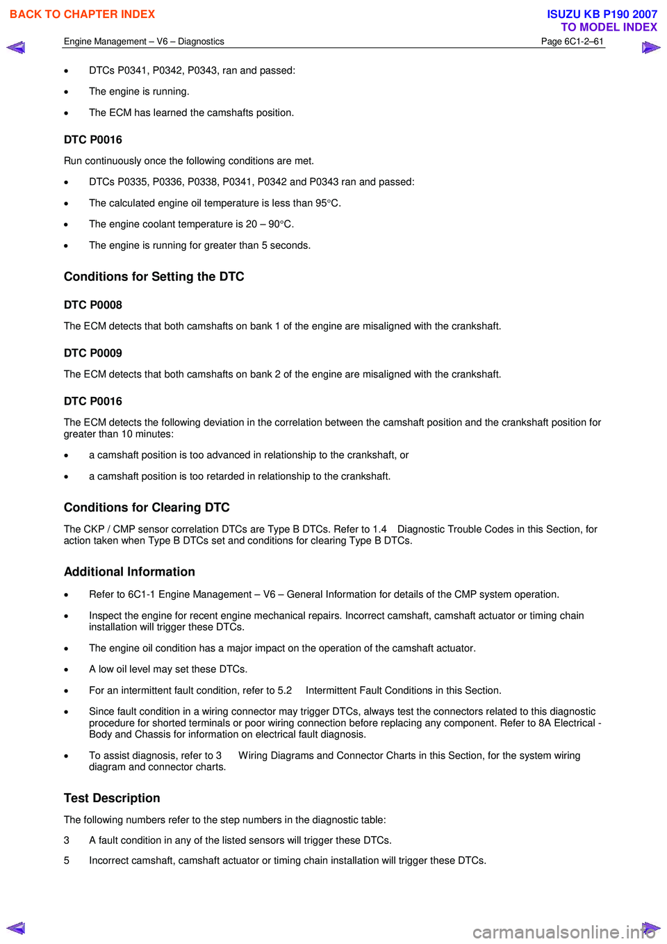
Conditions for Setting the DTC
DTC P0008
The ECM detects that both camshafts on bank 1 of the engine are misaligned with the crankshaft.
DTC P0009
The ECM detects that both camshafts on bank 2 of the engine are misaligned with the crankshaft.
DTC P0016
The ECM detects the following deviation in the correlation between the camshaft position and the crankshaft position for
greater than 10 minutes:
• a camshaft position is too advanced in relationship to the crankshaft, or
• a camshaft position is too retarded in relationship to the crankshaft.
Conditions for Clearing DTC
The CKP / CMP sensor correlation DTCs are Type B DTCs. Refer to 1.4 Diagnostic Trouble Codes in this Section, for
action taken when Type B DTCs set and conditions for clearing Type B DTCs.
Additional Information
• Refer to 6C1-1 Engine Management – V6 – General Information for details of the CMP system operation.
• Inspect the engine for recent engine mechanical repairs. Incorrect camshaft, camshaft actuator or timing chain
installation will trigger these DTCs.
• The engine oil condition has a major impact on the operation of the camshaft actuator.
• A low oil level may set these DTCs.
• For an intermittent fault condition, refer to 5.2 Intermittent Fault Conditions in this Section.
• Since fault condition in a wiring connector may trigger DTCs, always test the connectors related to this diagnostic
procedure for shorted terminals or poor wiring connection before replacing any component. Refer to 8A Electrical -
Body and Chassis for information on electrical fault diagnosis.
• To assist diagnosis, refer to 3 W iring Diagrams and Connector Charts in this Section, for the system wiring
diagram and connector charts.
Test Description
The following numbers refer to the step numbers in the diagnostic table:
3 A fault condition in any of the listed sensors will trigger these DTCs.
5 Incorrect camshaft, camshaft actuator or timing chain installation will trigger these DTCs.
BACK TO CHAPTER INDEX
TO MODEL INDEX
ISUZU KB P190 2007
Page 3342 of 6020
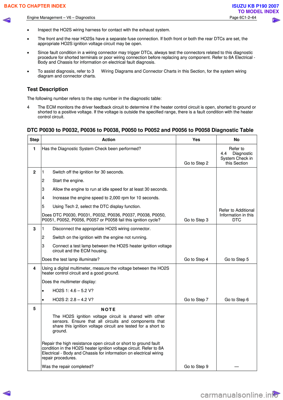
Engine Management – V6 – Diagnostics Page 6C1-2–64
• Inspect the HO2S wiring harness for contact with the exhaust system.
• The front and the rear HO2Ss have a separate fuse connection. If both front or both the rear DTCs are set, the
appropriate HO2S ignition voltage circuit may be open.
• Since fault condition in a wiring connector may trigger DTCs, always test the connectors related to this diagnostic
procedure for shorted terminals or poor wiring connection before replacing any component. Refer to 8A Electrical -
Body and Chassis for information on electrical fault diagnosis.
• To assist diagnosis, refer to 3 W iring Diagrams and Connector Charts in this Section, for the system wiring
diagram and connector charts.
Test Description
The following number refers to the step number in the diagnostic table:
4 The ECM monitors the driver feedback circuit to determine if the heater control circuit is open, shorted to ground or shorted to a positive voltage. If the voltage is outside the specified range, there is a fault condition with the heater
control circuit.
DTC P0030 to P0032, P0036 to P0038, P0050 to P0052 and P0056 to P0058 Diagnostic Table
Step Action Yes No
1 Has the Diagnostic System Check been performed?
Go to Step 2 Refer to
4.4 Diagnostic
System Check in this Section
2 1 Switch off the ignition for 30 seconds.
2 Start the engine.
3 Allow the engine to run at idle speed for at least 30 seconds.
4 Increase the engine speed to 2,000 rpm for 10 seconds.
5 Using Tech 2, select the DTC display function.
Does DTC P0030, P0031, P0032, P0036, P0037, P0038, P0050,
P0051, P0052, P0056, P0057 or P0058 fail this ignition cycle? Go to Step 3 Refer to Additional
Information in this DTC
3 1 Disconnect the appropriate HO2S wiring connector.
2 Switch on the ignition with the engine not running.
3 Connect a test lamp between the HO2S heater ignition voltage circuit and the ECM housing.
Does the test lamp illuminate? Go to Step 4 Go to Step 5
4 Using a digital multimeter, measure the voltage between the HO2S
heater control circuit and a good ground.
Does the multimeter display:
• HO2S 1: 4.6 – 5.2 V?
• HO2S 2: 2.8 – 4.2 V? Go to Step 7 Go to Step 6
5
NOTE
The HO2S ignition voltage circuit is shared with other
sensors. Ensure that all circuits and components that
share this ignition voltage circuit are tested for a short to
ground.
Repair the high resistance open circuit or short to ground fault
condition in the HO2S heater ignition voltage circuit. Refer to 8A
Electrical - Body and Chassis for information on electrical wiring
repair procedures.
W as the repair completed? Go to Step 9 —
BACK TO CHAPTER INDEX
TO MODEL INDEX
ISUZU KB P190 2007
Page 3343 of 6020
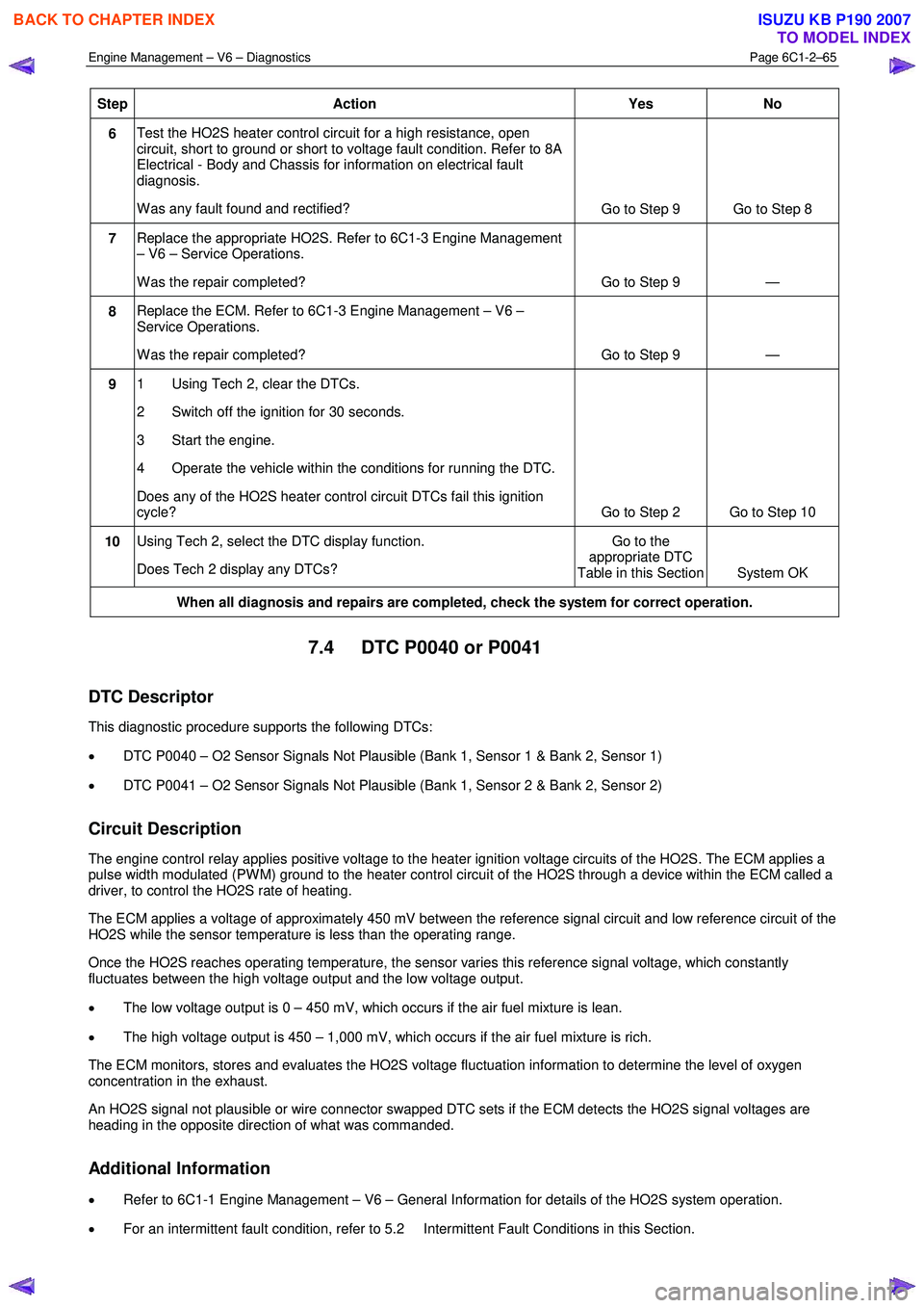
Engine Management – V6 – Diagnostics Page 6C1-2–65
Step Action Yes No
6 Test the HO2S heater control circuit for a high resistance, open
circuit, short to ground or short to voltage fault condition. Refer to 8A
Electrical - Body and Chassis for information on electrical fault
diagnosis.
W as any fault found and rectified? Go to Step 9 Go to Step 8
7 Replace the appropriate HO2S. Refer to 6C1-3 Engine Management
– V6 – Service Operations.
W as the repair completed? Go to Step 9 —
8 Replace the ECM. Refer to 6C1-3 Engine Management – V6 –
Service Operations.
W as the repair completed? Go to Step 9 —
9 1 Using Tech 2, clear the DTCs.
2 Switch off the ignition for 30 seconds.
3 Start the engine.
4 Operate the vehicle within the conditions for running the DTC.
Does any of the HO2S heater control circuit DTCs fail this ignition
cycle? Go to Step 2 Go to Step 10
10 Using Tech 2, select the DTC display function.
Does Tech 2 display any DTCs? Go to the
appropriate DTC
Table in this Section System OK
When all diagnosis and repairs are completed, check the system for correct operation.
7.4 DTC P0040 or P0041
DTC Descriptor
This diagnostic procedure supports the following DTCs:
• DTC P0040 – O2 Sensor Signals Not Plausible (Bank 1, Sensor 1 & Bank 2, Sensor 1)
• DTC P0041 – O2 Sensor Signals Not Plausible (Bank 1, Sensor 2 & Bank 2, Sensor 2)
Circuit Description
The engine control relay applies positive voltage to the heater ignition voltage circuits of the HO2S. The ECM applies a
pulse width modulated (PW M) ground to the heater control circuit of the HO2S through a device within the ECM called a
driver, to control the HO2S rate of heating.
The ECM applies a voltage of approximately 450 mV between the reference signal circuit and low reference circuit of the
HO2S while the sensor temperature is less than the operating range.
Once the HO2S reaches operating temperature, the sensor varies this reference signal voltage, which constantly
fluctuates between the high voltage output and the low voltage output.
• The low voltage output is 0 – 450 mV, which occurs if the air fuel mixture is lean.
• The high voltage output is 450 – 1,000 mV, which occurs if the air fuel mixture is rich.
The ECM monitors, stores and evaluates the HO2S voltage fluctuation information to determine the level of oxygen
concentration in the exhaust.
An HO2S signal not plausible or wire connector swapped DTC sets if the ECM detects the HO2S signal voltages are
heading in the opposite direction of what was commanded.
Additional Information
• Refer to 6C1-1 Engine Management – V6 – General Information for details of the HO2S system operation.
• For an intermittent fault condition, refer to 5.2 Intermittent Fault Conditions in this Section.
BACK TO CHAPTER INDEX
TO MODEL INDEX
ISUZU KB P190 2007
Page 3344 of 6020
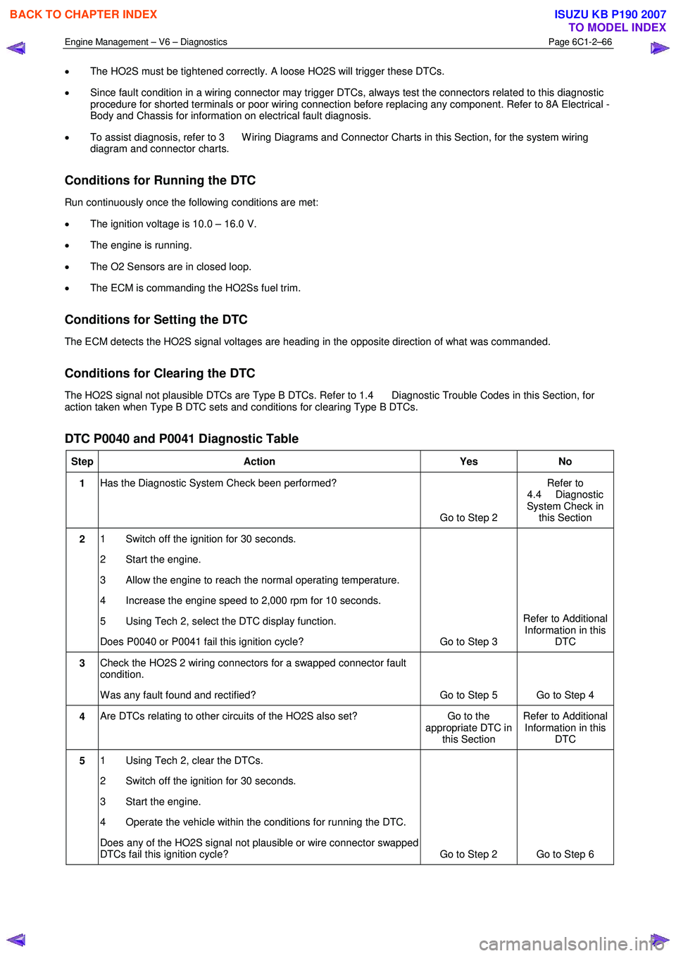
Engine Management – V6 – Diagnostics Page 6C1-2–66
• The HO2S must be tightened correctly. A loose HO2S will trigger these DTCs.
• Since fault condition in a wiring connector may trigger DTCs, always test the connectors related to this diagnostic
procedure for shorted terminals or poor wiring connection before replacing any component. Refer to 8A Electrical -
Body and Chassis for information on electrical fault diagnosis.
• To assist diagnosis, refer to 3 W iring Diagrams and Connector Charts in this Section, for the system wiring
diagram and connector charts.
Conditions for Running the DTC
Run continuously once the following conditions are met:
• The ignition voltage is 10.0 – 16.0 V.
• The engine is running.
• The O2 Sensors are in closed loop.
• The ECM is commanding the HO2Ss fuel trim.
Conditions for Setting the DTC
The ECM detects the HO2S signal voltages are heading in the opposite direction of what was commanded.
Conditions for Clearing the DTC
The HO2S signal not plausible DTCs are Type B DTCs. Refer to 1.4 Diagnostic Trouble Codes in this Section, for
action taken when Type B DTC sets and conditions for clearing Type B DTCs.
DTC P0040 and P0041 Diagnostic Table
Step Action Yes No
1 Has the Diagnostic System Check been performed?
Go to Step 2 Refer to
4.4 Diagnostic
System Check in this Section
2 1 Switch off the ignition for 30 seconds.
2 Start the engine.
3 Allow the engine to reach the normal operating temperature.
4 Increase the engine speed to 2,000 rpm for 10 seconds.
5 Using Tech 2, select the DTC display function.
Does P0040 or P0041 fail this ignition cycle? Go to Step 3 Refer to Additional
Information in this DTC
3 Check the HO2S 2 wiring connectors for a swapped connector fault
condition.
W as any fault found and rectified? Go to Step 5 Go to Step 4
4 Are DTCs relating to other circuits of the HO2S also set? Go to the
appropriate DTC in this Section Refer to Additional
Information in this DTC
5 1 Using Tech 2, clear the DTCs.
2 Switch off the ignition for 30 seconds.
3 Start the engine.
4 Operate the vehicle within the conditions for running the DTC.
Does any of the HO2S signal not plausible or wire connector swapped
DTCs fail this ignition cycle? Go to Step 2 Go to Step 6
BACK TO CHAPTER INDEX
TO MODEL INDEX
ISUZU KB P190 2007