2007 ISUZU KB P190 fuse
[x] Cancel search: fusePage 1942 of 6020
ENGINE CONTROL SYSTEM (4JK1/4JJ1) 6E-325
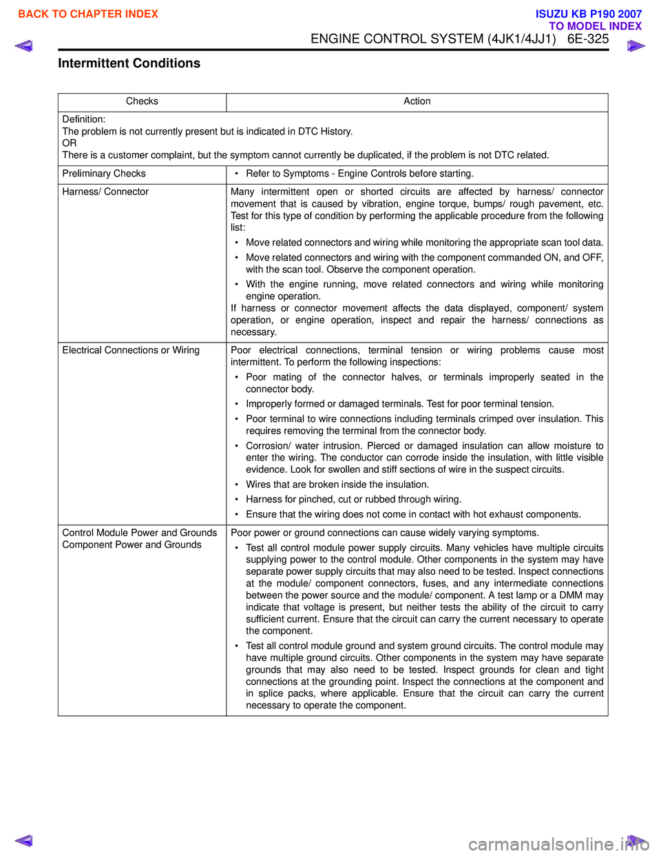
Intermittent Conditions
ChecksAction
Definition:
The problem is not currently present but is indicated in DTC History.
OR
There is a customer complaint, but the symptom cannot currently be duplicated, if the problem is not DTC related.
Preliminary Checks • Refer to Symptoms - Engine Controls before starting.
Harness/ Connector Many intermittent open or shorted circuits are affected by harness/ connector
movement that is caused by vibration, engine torque, bumps/ rough pavement, etc.
Test for this type of condition by performing the applicable procedure from the following
list:
• Move related connectors and wiring while monitoring the appropriate scan tool data.
• Move related connectors and wiring with the component commanded ON, and OFF, with the scan tool. Observe the component operation.
• With the engine running, move related connectors and wiring while monitoring engine operation.
If harness or connector movement affects the data displayed, component/ system
operation, or engine operation, inspect and repair the harness/ connections as
necessary.
Electrical Connections or Wiring Poor electrical connections, terminal tension or wiring problems cause most intermittent. To perform the following inspections:
• Poor mating of the connector halves, or terminals improperly seated in the connector body.
• Improperly formed or damaged terminals. Test for poor terminal tension.
• Poor terminal to wire connections including terminals crimped over insulation. This requires removing the terminal from the connector body.
• Corrosion/ water intrusion. Pierced or damaged insulation can allow moisture to enter the wiring. The conductor can corrode inside the insulation, with little visible
evidence. Look for swollen and stiff sections of wire in the suspect circuits.
• Wires that are broken inside the insulation.
• Harness for pinched, cut or rubbed through wiring.
• Ensure that the wiring does not come in contact with hot exhaust components.
Control Module Power and Grounds
Component Power and Grounds Poor power or ground connections can cause widely varying symptoms.
• Test all control module power supply circuits. Many vehicles have multiple circuits supplying power to the control module. Other components in the system may have
separate power supply circuits that may also need to be tested. Inspect connections
at the module/ component connectors, fuses, and any intermediate connections
between the power source and the module/ component. A test lamp or a DMM may
indicate that voltage is present, but neither tests the ability of the circuit to carry
sufficient current. Ensure that the circuit can carry the current necessary to operate
the component.
• Test all control module ground and system ground circuits. The control module may have multiple ground circuits. Other components in the system may have separate
grounds that may also need to be tested. Inspect grounds for clean and tight
connections at the grounding point. Inspect the connections at the component and
in splice packs, where applicable. Ensure that the circuit can carry the current
necessary to operate the component.
BACK TO CHAPTER INDEX
TO MODEL INDEX
ISUZU KB P190 2007
Page 2003 of 6020
ENGINE DIAGNOSIS (C24SE) 6-3
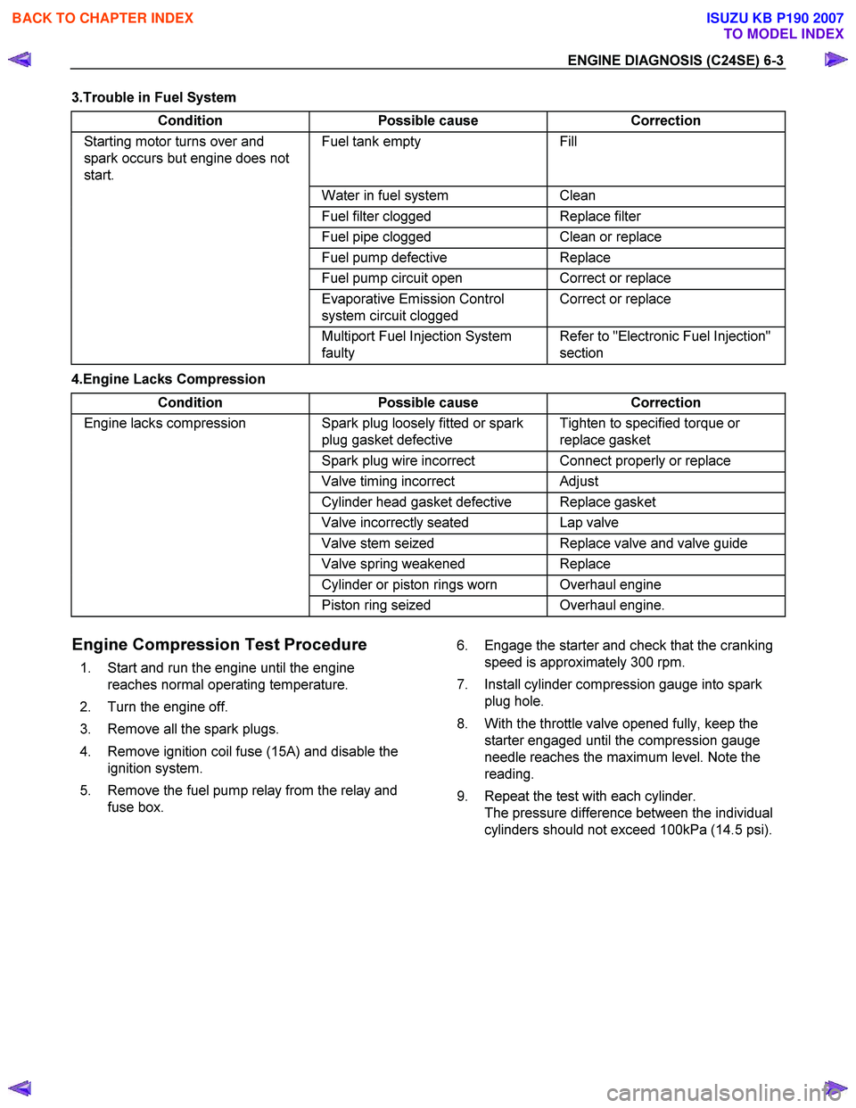
3.Trouble in Fuel System Condition Possible cause Correction
Starting motor turns over and
spark occurs but engine does not
start. Fuel tank empty Fill
Water in fuel system Clean
Fuel filter clogged Replace filter
Fuel pipe clogged Clean or replace
Fuel pump defective Replace
Fuel pump circuit open Correct or replace
Evaporative Emission Control
system circuit clogged Correct or replace
Multiport Fuel Injection System
faulty Refer to "Electronic Fuel Injection"
section
4.Engine Lacks Compression
Condition Possible cause Correction
Engine lacks compression Spark plug loosely fitted or spark
plug gasket defective Tighten to specified torque or
replace gasket
Spark plug wire incorrect Connect properly or replace
Valve timing incorrect Adjust
Cylinder head gasket defective Replace gasket
Valve incorrectly seated Lap valve
Valve stem seized Replace valve and valve guide
Valve spring weakened Replace
Cylinder or piston rings worn Overhaul engine
Piston ring seized Overhaul engine.
Engine Compression Test Procedure
1. Start and run the engine until the engine
reaches normal operating temperature.
2. Turn the engine off.
3. Remove all the spark plugs.
4. Remove ignition coil fuse (15A) and disable the ignition system.
5. Remove the fuel pump relay from the relay and fuse box. 6. Engage the starter and check that the cranking
speed is approximately 300 rpm.
7. Install cylinder compression gauge into spark plug hole.
8. With the throttle valve opened fully, keep the starter engaged until the compression gauge
needle reaches the maximum level. Note the
reading.
9. Repeat the test with each cylinder. The pressure difference between the individual
cylinders should not exceed 100kPa (14.5 psi).
BACK TO CHAPTER INDEX
TO MODEL INDEX
ISUZU KB P190 2007
Page 2139 of 6020
6D1-2 ENGINE ELECTRICAL
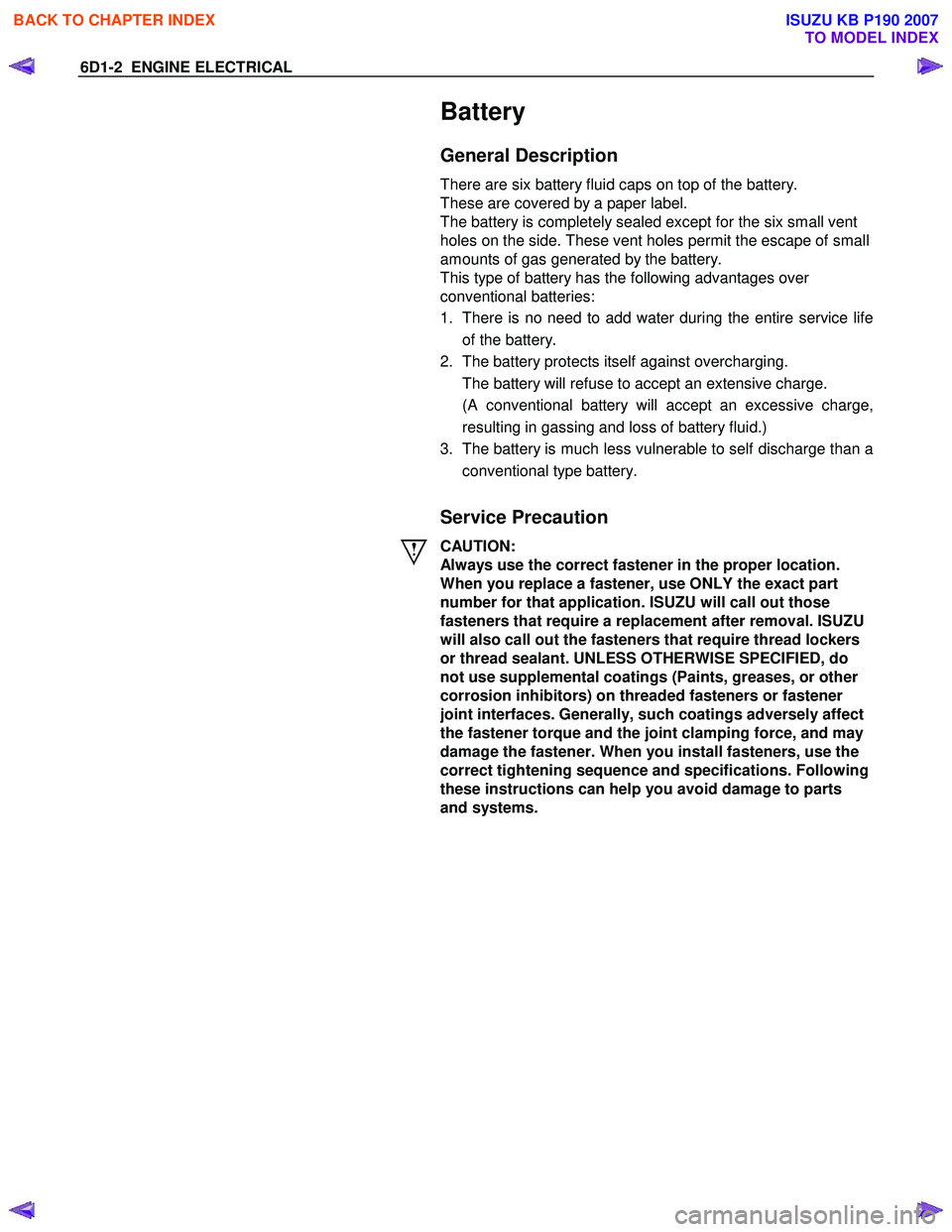
Battery
General Description
There are six battery fluid caps on top of the battery.
These are covered by a paper label.
The battery is completely sealed except for the six small vent
holes on the side. These vent holes permit the escape of small
amounts of gas generated by the battery.
This type of battery has the following advantages over
conventional batteries:
1. There is no need to add water during the entire service life
of the battery.
2. The battery protects itself against overcharging.
The battery will refuse to accept an extensive charge.
(A conventional battery will accept an excessive charge, resulting in gassing and loss of battery fluid.)
3. The battery is much less vulnerable to self discharge than a conventional type battery.
Service Precaution
CAUTION:
Always use the correct fastener in the proper location.
When you replace a fastener, use ONLY the exact part
number for that application. ISUZU will call out those
fasteners that require a replacement after removal. ISUZU
will also call out the fasteners that require thread lockers
or thread sealant. UNLESS OTHERWISE SPECIFIED, do
not use supplemental coatings (Paints, greases, or other
corrosion inhibitors) on threaded fasteners or fastener
joint interfaces. Generally, such coatings adversely affect
the fastener torque and the joint clamping force, and may
damage the fastener. When you install fasteners, use the
correct tightening sequence and specifications. Following
these instructions can help you avoid damage to parts
and systems.
BACK TO CHAPTER INDEX
TO MODEL INDEX
ISUZU KB P190 2007
Page 2171 of 6020
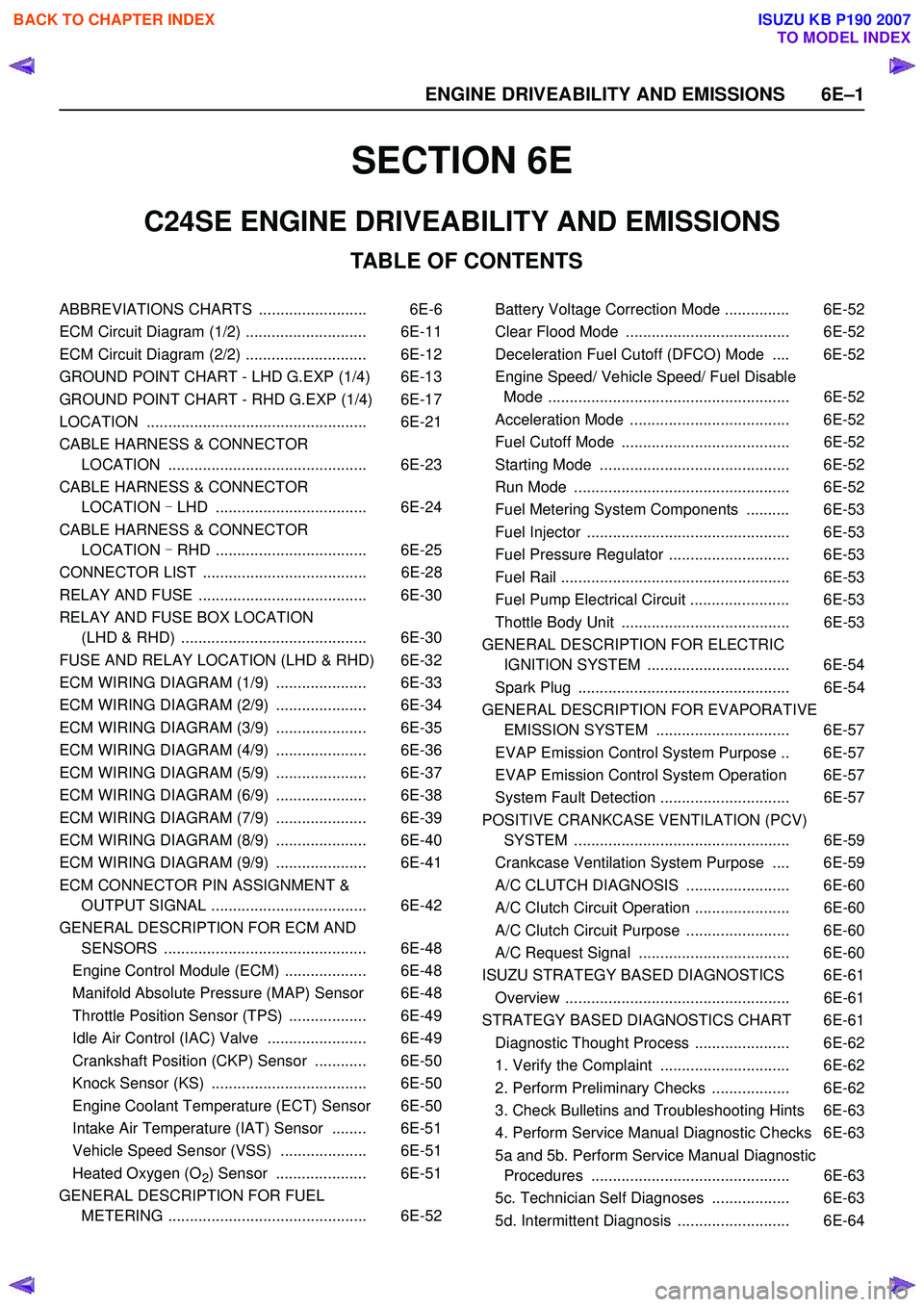
SECTION 6E
TABLE OF CONTENTS
C24SE ENGINE DRIVEABILITY AND EMISSIONS
ABBREVIATIONS CHARTS ......................... 6E-6
ECM Circuit Diagram (1/2) ............................ 6E-11
ECM Circuit Diagram (2/2) ............................ 6E-12
GROUND POINT CHART - LHD G.EXP (1/4) 6E-13
GROUND POINT CHART - RHD G.EXP (1/4) 6E-17
LOCATION ................................................... 6E-21
CABLE HARNESS & CONNECTOR LOCATION .............................................. 6E-23
CABLE HARNESS & CONNECTOR LOCATION - LHD ................................... 6E-24
CABLE HARNESS & CONNECTOR LOCATION - RHD ................................... 6E-25
CONNECTOR LIST ...................................... 6E-28
RELAY AND FUSE ....................................... 6E-30
RELAY AND FUSE BOX LOCATION (LHD & RHD) ........................................... 6E-30
FUSE AND RELAY LOCATION (LHD & RHD) 6E-32
ECM WIRING DIAGRAM (1/9) ..................... 6E-33
ECM WIRING DIAGRAM (2/9) ..................... 6E-34
ECM WIRING DIAGRAM (3/9) ..................... 6E-35
ECM WIRING DIAGRAM (4/9) ..................... 6E-36
ECM WIRING DIAGRAM (5/9) ..................... 6E-37
ECM WIRING DIAGRAM (6/9) ..................... 6E-38
ECM WIRING DIAGRAM (7/9) ..................... 6E-39
ECM WIRING DIAGRAM (8/9) ..................... 6E-40
ECM WIRING DIAGRAM (9/9) ..................... 6E-41
ECM CONNECTOR PIN ASSIGNMENT & OUTPUT SIGNAL .................................... 6E-42
GENERAL DESCRIPTION FOR ECM AND SENSORS ............................................... 6E-48
Engine Control Module (ECM) ................... 6E-48
Manifold Absolute Pressure (MAP) Sensor 6E-48
Throttle Position Sensor (TPS) .................. 6E-49
Idle Air Control (IAC) Valve ....................... 6E-49
Crankshaft Position (CKP) Sensor ............ 6E-50
Knock Sensor (KS) .................................... 6E-50
Engine Coolant Temperature (ECT) Sensor 6E-50
Intake Air Temperature (IAT) Sensor ........ 6E-51
Vehicle Speed Sensor (VSS) .................... 6E-51
Heated Oxygen (O
2) Sensor ..................... 6E-51
GENERAL DESCRIPTION FOR FUEL METERING .............................................. 6E-52 Battery Voltage Correction Mode ............... 6E-52
Clear Flood Mode ...................................... 6E-52
Deceleration Fuel Cutoff (DFCO) Mode .... 6E-52
Engine Speed/ Vehicle Speed/ Fuel Disable Mode ........................................................ 6E-52
Acceleration Mode ..................................... 6E-52
Fuel Cutoff Mode ....................................... 6E-52
Starting Mode ............................................ 6E-52
Run Mode .................................................. 6E-52
Fuel Metering System Components .......... 6E-53
Fuel Injector ............................................... 6E-53
Fuel Pressure Regulator ............................ 6E-53
Fuel Rail ..................................................... 6E-53
Fuel Pump Electrical Circuit ....................... 6E-53
Thottle Body Unit ....................................... 6E-53
GENERAL DESCRIPTION FOR ELECTRIC IGNITION SYSTEM ................................. 6E-54
Spark Plug ................................................. 6E-54
GENERAL DESCRIPTION FOR EVAPORATIVE EMISSION SYSTEM ............................... 6E-57
EVAP Emission Control System Purpose .. 6E-57
EVAP Emission Control System Operation 6E-57
System Fault Detection .............................. 6E-57
POSITIVE CRANKCASE VENTILATION (PCV) SYSTEM .................................................. 6E-59
Crankcase Ventilation System Purpose .... 6E-59
A/C CLUTCH DIAGNOSIS ........................ 6E-60
A/C Clutch Circuit Operation ...................... 6E-60
A/C Clutch Circuit Purpose ........................ 6E-60
A/C Request Signal ................................... 6E-60
ISUZU STRATEGY BASED DIAGNOSTICS 6E-61
Overview .................................................... 6E-61
STRATEGY BASED DIAGNOSTICS CHART 6E-61 Diagnostic Thought Process ...................... 6E-62
1. Verify the Complaint .............................. 6E-62
2. Perform Preliminary Checks .................. 6E-62
3. Check Bulletins and Troubleshooting Hints 6E-63
4. Perform Service Manual Diagnostic Checks 6E-63
5a and 5b. Perform Service Manual Diagnostic Procedures .............................................. 6E-63
5c. Technician Self Diagnoses .................. 6E-63
5d. Intermittent Diagnosis .......................... 6E-64
6 E –1
E N GINE DRIV EABILITY AND E M IS SIONS
BACK TO CHAPTER INDEX
TO MODEL INDEX
ISUZU KB P190 2007
Page 2199 of 6020
ENGINE DRIVEABILITY AND EMISSIONS 6E–29
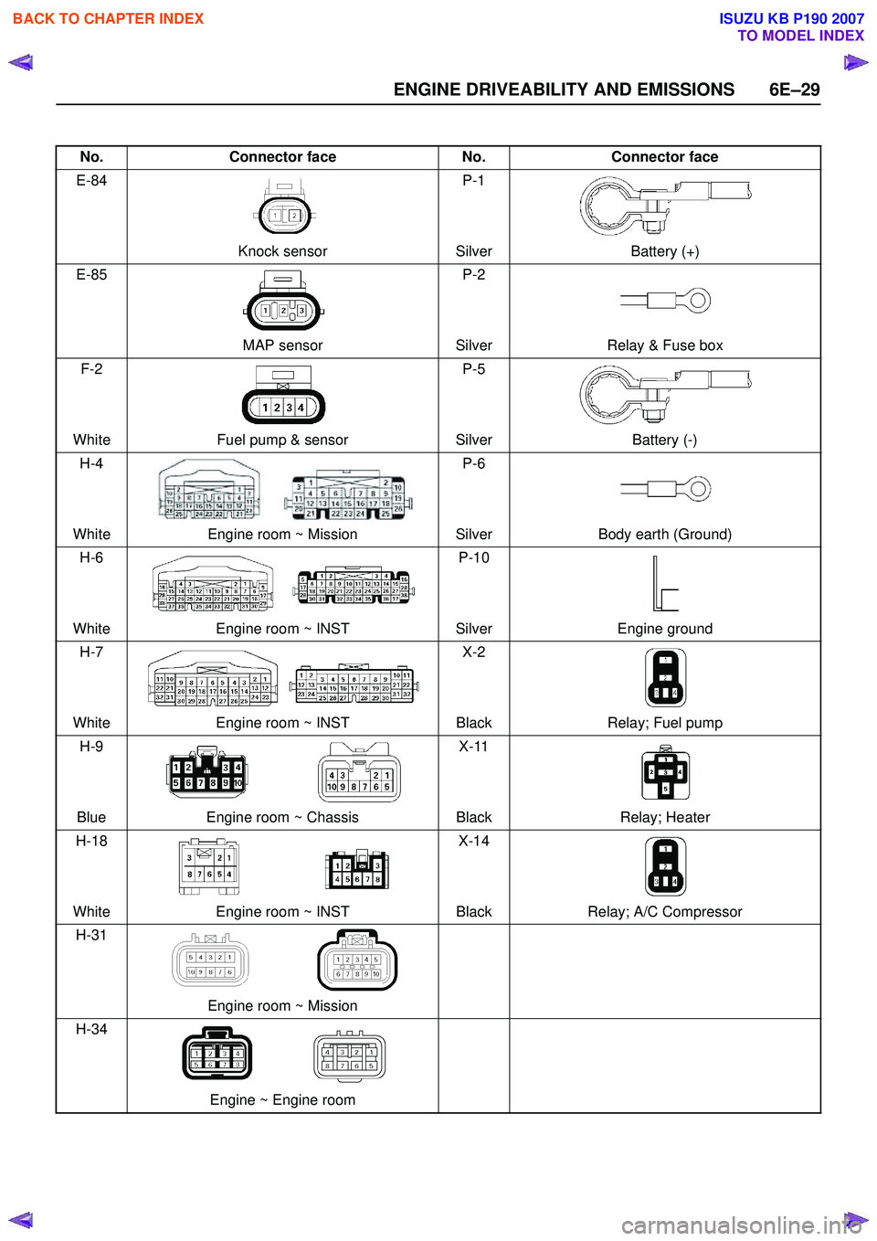
No.Connector face No.Connector face
E-84
Knock sensor P-1
Silver Battery (+)
E-85
MAP sensor P-2
Silver Relay & Fuse box
F-2
White Fuel pump & sensor P-5
Silver Battery (-)
H-4
White Engine room ~ Mission P-6
Silver Body earth (Ground)
H-6
White Engine room ~ INST P-10
Silver Engine ground
H-7
White Engine room ~ INST X-2
Black Relay; Fuel pump
H-9
Blue Engine room ~ Chassis X-11
Black Relay; Heater
H-18
White Engine room ~ INST X-14
Black Relay; A/C Compressor
H-31
Engine room ~ Mission
H-34
Engine ~ Engine room
BACK TO CHAPTER INDEX
TO MODEL INDEX
ISUZU KB P190 2007
Page 2200 of 6020
6E–30 ENGINE DRIVEABILITY AND EMISSIONS
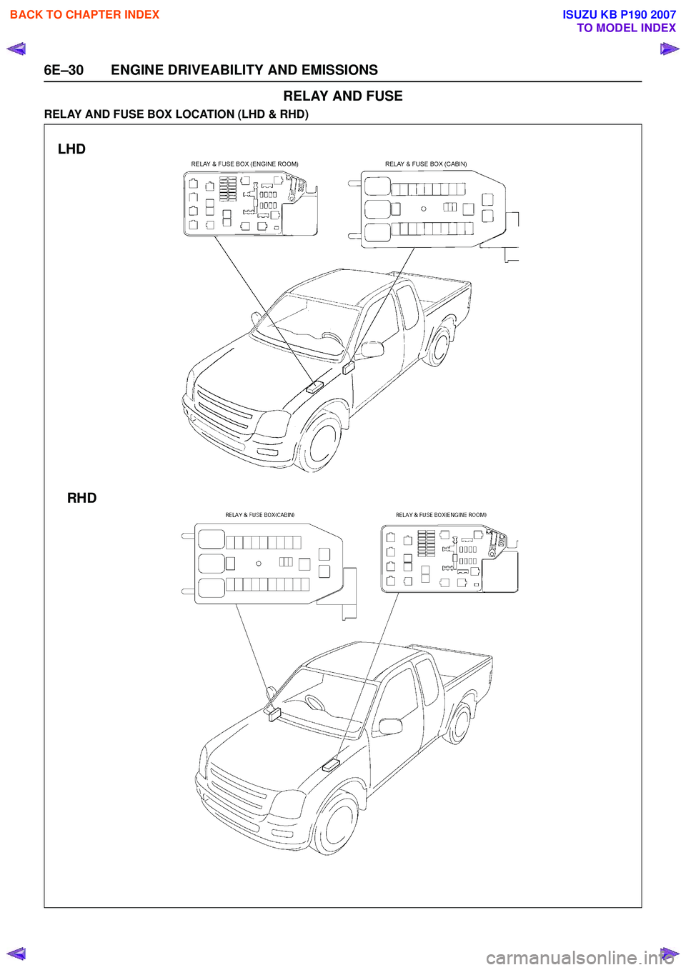
RELAY AND FUSE
RELAY AND FUSE BOX LOCATION (LHD & RHD)
LHDRHD
BACK TO CHAPTER INDEX
TO MODEL INDEX
ISUZU KB P190 2007
Page 2201 of 6020
ENGINE DRIVEABILITY AND EMISSIONS 6E–31
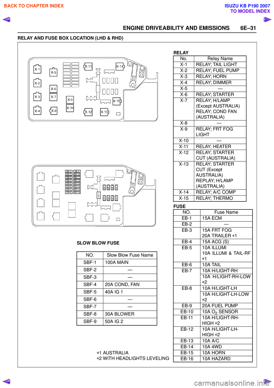
RELAY AND FUSE BOX LOCATION (LHD & RHD)
RELAYNo. Relay Name
X-1 RELAY; TAIL LIGHT
X-2 RELAY; FUEL PUMP
X-3 RELAY; HORN
X-4 RELAY; DIMMER
X-5 —
X-6 RELAY; STARTER
X-7 RELAY; H/LAMP (Except AUSTRALIA)
RELAY; COND FAN
(AUSTRALIA)
X-8 —
X-9 RELAY; FRT FOG LIGHT
X-10 —
X-11 RELAY; HEATER
X-12 RELAY; STARTER CUT (AUSTRALIA)
X-13 RELAY; STARTER CUT (Except
AUSTRALIA)
REPLAY; H/LAMP
(AUSTRALIA)
X-14 RELAY; A/C COMP
X-15 RELAY; THERMO
SLOW BLOW FUSE
NO. Slow Blow Fuse Name
SBF-1 100A MAIN
SBF-2 —
SBF-3 —
SBF-4 20A COND, FAN
SBF-5 40A IG 1
SBF-6 —
SBF-7 —
SBF-8 30A BLOWER
SBF-9 50A IG 2
* 1 AUSTRALIA
* 2 WITH HEADLIGHTS LEVELING
FUSE
NO. Fuse Name
EB-1 15A ECM
EB-2 —
EB-3 15A FRT FOG 20A TRAILER *1
EB-4 15A ACG (S)
EB-5 10A ILLUMI 10A ILLUMI & TAIL-RF
* 1
EB-6 10A TAIL
EB-7 10A H/LIGHT-RH 10A H/LIGHT-RH-LOW
* 2
EB-8 10A H/LIGHT-LH 10A H/LIGHT-LH-LOW
* 2
EB-9 20A FUEL PUMP
EB-10 10A O
2 SENSOR
EB-11 10A H/LIGHT-RH- HIGH *2
EB-12 10A H/LIGHT-LH- HIGH *2
EB-13 10A A/C
EB-14 10A 4WD
EB-15 10A HORN
EB-16 10A HAZARD
BACK TO CHAPTER INDEX
TO MODEL INDEX
ISUZU KB P190 2007
Page 2202 of 6020
6E–32 ENGINE DRIVEABILITY AND EMISSIONS
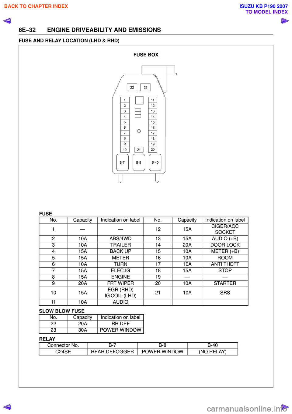
FUSE AND RELAY LOCATION (LHD & RHD)
FUSE
SLOW BLOW FUSE
RELAY No. Capacity Indication on label No. Capacity Indication on label
1— — 1 215A CIGER/ACC
SOCKET
2 10A ABS/4WD 13 15A AUDIO (+B)
3 10A TRAILER 14 20A DOOR LOCK
4 15A BACK UP 15 10A METER (+B)
5 15A METER16 10A ROOM
6 10A TURN17 10A ANTI THEFT
7 15A ELEC.IG 18 15ASTOP
815A ENGINE 19 — —
9 20A FRT WIPER 20 10A STARTER
10 15A EGR (RHD)
IG.COIL (LHD) 21 10A
SRS
11 10A AUDIO
No. Capacity Indication on label 22 20A RR DEF
23 30A POWER WINDOW
Connector No. B-7B-8B-40
C24SE REAR DEFOGGER POWER WINDOW (NO RELAY)
FUSE BOX
BACK TO CHAPTER INDEX
TO MODEL INDEX
ISUZU KB P190 2007