2007 ISUZU KB P190 fuse
[x] Cancel search: fusePage 2403 of 6020
ENGINE DRIVEABILITY AND EMISSIONS 6E–233
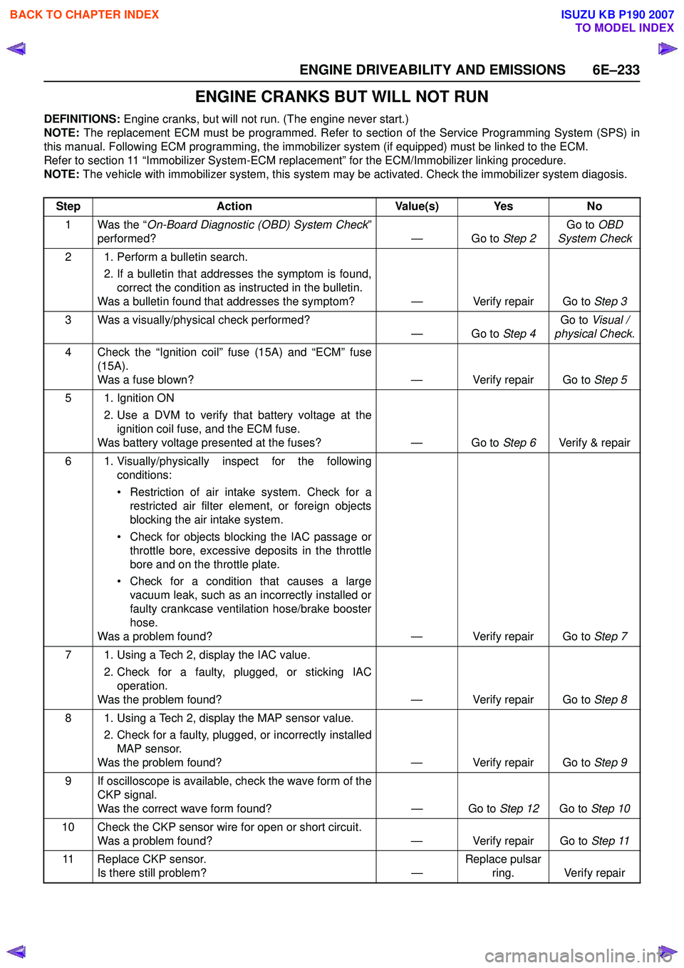
ENGINE CRANKS BUT WILL NOT RUN
DEFINITIONS: Engine cranks, but will not run. (The engine never start.)
NOTE: The replacement ECM must be programmed. Refer to section of the Service Programming System (SPS) in
this manual. Following ECM programming, the immobilizer system (if equipped) must be linked to the ECM.
Refer to section 11 “Immobilizer System-ECM replacement” for the ECM/Immobilizer linking procedure.
NOTE: The vehicle with immobilizer system, this system may be activated. Check the immobilizer system diagosis.
Step Action Value(s) Yes No
1 Was the “ On-Board Diagnostic (OBD) System Check ”
performed? — Go to Step 2Go to
OBD
System Check
2 1. Perform a bulletin search. 2. If a bulletin that addresses the symptom is found,correct the condition as instructed in the bulletin.
Was a bulletin found that addresses the symptom? — Verify repair Go to Step 3
3 Was a visually/physical check performed? —Go to Step 4Go to
Visual /
physical Check.
4 Check the “Ignition coil” fuse (15A) and “ECM” fuse (15A).
Was a fuse blown? — Verify repair Go to Step 5
5 1. Ignition ON 2. Use a DVM to verify that battery voltage at theignition coil fuse, and the ECM fuse.
Was battery voltage presented at the fuses? — Go to Step 6Verify & repair
6 1. Visually/physically inspect for the following conditions:
• Restriction of air intake system. Check for a restricted air filter element, or foreign objects
blocking the air intake system.
• Check for objects blocking the IAC passage or throttle bore, excessive deposits in the throttle
bore and on the throttle plate.
• Check for a condition that causes a large vacuum leak, such as an incorrectly installed or
faulty crankcase ventilation hose/brake booster
hose.
Was a problem found? — Verify repair Go to Step 7
7 1. Using a Tech 2, display the IAC value. 2. Check for a faulty, plugged, or sticking IACoperation.
Was the problem found? — Verify repair Go to Step 8
8 1. Using a Tech 2, display the MAP sensor value. 2. Check for a faulty, plugged, or incorrectly installedMAP sensor.
Was the problem found? — Verify repair Go to Step 9
9 If oscilloscope is available, check the wave form of the CKP signal.
Was the correct wave form found? — Go to Step 12Go to Step 10
10 Check the CKP sensor wire for open or short circuit. Was a problem found? — Verify repair Go to Step 11
11 Replace CKP sensor. Is there still problem? —Replace pulsar
ring. Verify repair
BACK TO CHAPTER INDEX
TO MODEL INDEX
ISUZU KB P190 2007
Page 2517 of 6020
Engine Mechanical – V6 Page 6A1–38
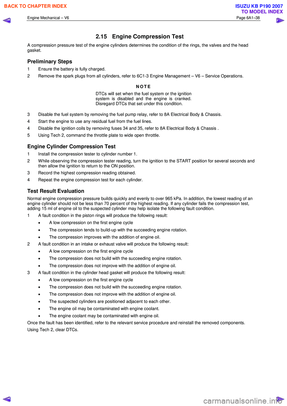
2.15 Engine Compression Test
A compression pressure test of the engine cylinders determines the condition of the rings, the valves and the head
gasket.
Preliminary Steps
1 Ensure the battery is fully charged.
2 Remove the spark plugs from all cylinders, refer to 6C1-3 Engine Management – V6 – Service Operations.
NOTE
DTCs will set when the fuel system or the ignition
system is disabled and the engine is cranked.
Disregard DTCs that set under this condition.
3 Disable the fuel system by removing the fuel pump relay, refer to 8A Electrical Body & Chassis.
4 Start the engine to use any residual fuel from the fuel lines.
4 Disable the ignition coils by removing fuses 34 and 35, refer to 8A Electrical Body & Chassis .
5 Using Tech 2, command the throttle plate to wide open throttle.
Engine Cylinder Compression Test
1 Install the compression tester to cylinder number 1.
2 W hile observing the compression tester reading, turn the ignition to the START position for several seconds and then allow the ignition to return to the ON position.
3 Record the highest compression reading obtained.
4 Repeat the engine compression test for each cylinder.
Test Result Evaluation
Normal engine compression pressure builds quickly and evenly to over 965 kPa. In addition, the lowest reading of an
engine cylinder should not be less than 70 percent of the highest reading. If any cylinder fails the compression test,
adding 15 ml of engine oil to the suspected cylinder may help isolate the following fault condition.
1 A fault condition in the piston rings will produce the following result:
• A low compression on the first engine cycle
• The compression tends to build-up with the succeeding engine rotation.
• The compression improves with the addition of engine oil.
2 A fault condition in an intake or exhaust valve will produce the following result:
• A low compression on the first engine cycle
• The compression does not build with the succeeding engine rotation.
• The compression does not improve with the addition of engine oil.
3 A fault condition in the cylinder head gasket will produce the following result:
• A low compression on the first engine cycle
• The compression does not build with the succeeding engine rotation.
• The compression does not improve with the addition of engine oil.
• The suspected cylinders are positioned adjacent to each other.
• The engine oil may be contaminated with engine coolant.
• The engine coolant may be contaminated with engine oil.
Once the fault has been identified, refer to the relevant service procedure and reinstall the removed components.
Using Tech 2, clear DTCs.
BACK TO CHAPTER INDEX
TO MODEL INDEX
ISUZU KB P190 2007
Page 2527 of 6020
Engine Mechanical – V6 Page 6A1–48
NOTE
Pilling is the small balls (pills) or strings of rubber
in the belt grooves caused by the accumulation of
rubber dust.
Diagnostic Aids
Vibration from the engine may cause a body component or other parts to emit a rumbling noise.
The drive belt may have a condition that cannot be seen or felt. Sometimes the replacement of the belt may be the only
way to confirm the belt is faulty.
If the drive belt has been replaced and the diagnostic table completed, but the rumble is still present only when the drive
belt is installed, an accessory drive component such as the A/C compressor may be the cause. Varying the load to each
accessory drive component in turn, should help isolate which component is causing the noise.
Test Description
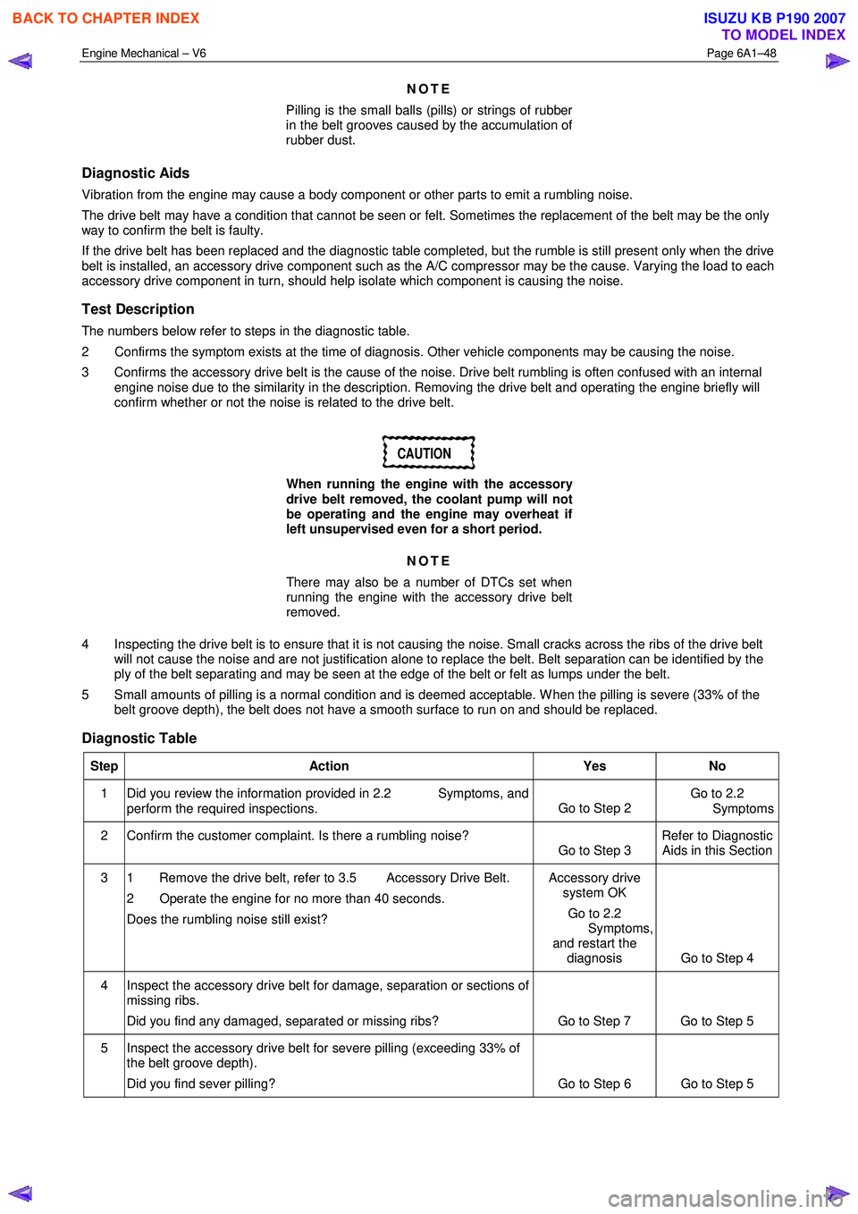
The numbers below refer to steps in the diagnostic table.
2 Confirms the symptom exists at the time of diagnosis. Other vehicle components may be causing the noise.
3 Confirms the accessory drive belt is the cause of the noise. Drive belt rumbling is often confused with an internal engine noise due to the similarity in the description. Removing the drive belt and operating the engine briefly will
confirm whether or not the noise is related to the drive belt.
CAUTION
When running the engine with the accessory
drive belt removed, the coolant pump will not
be operating and the engine may overheat if
left unsupervised even for a short period.
NOTE
There may also be a number of DTCs set when
running the engine with the accessory drive belt
removed.
4 Inspecting the drive belt is to ensure that it is not causing the noise. Small cracks across the ribs of the drive belt will not cause the noise and are not justification alone to replace the belt. Belt separation can be identified by the
ply of the belt separating and may be seen at the edge of the belt or felt as lumps under the belt.
5 Small amounts of pilling is a normal condition and is deemed acceptable. W hen the pilling is severe (33% of the belt groove depth), the belt does not have a smooth surface to run on and should be replaced.
Diagnostic Table
Step Action Yes No
1 Did you review the information provided in 2.2 Symptoms, and
perform the required inspections. Go to Step 2 Go to 2.2
Symptoms
2 Confirm the customer complaint. Is there a rumbling noise? Go to Step 3 Refer to Diagnostic
Aids in this Section
3 1 Remove the drive belt, refer to 3.5 Accessory Drive Belt.
2 Operate the engine for no more than 40 seconds.
Does the rumbling noise still exist? Accessory drive
system OK
Go to 2.2
Symptoms,
and restart the diagnosis Go to Step 4
4 Inspect the accessory drive belt for damage, separation or sections of missing ribs.
Did you find any damaged, separated or missing ribs? Go to Step 7 Go to Step 5
5 Inspect the accessory drive belt for severe pilling (exceeding 33% of the belt groove depth).
Did you find sever pilling? Go to Step 6 Go to Step 5
BACK TO CHAPTER INDEX
TO MODEL INDEX
ISUZU KB P190 2007
Page 2528 of 6020
Engine Mechanical – V6 Page 6A1–49
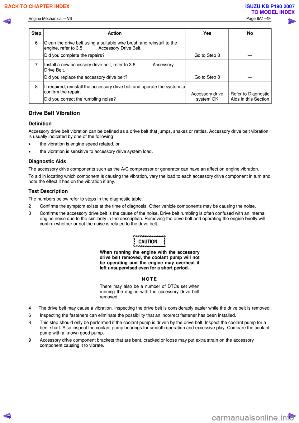
Step Action Yes No
6 Clean the drive belt using a suitable wire brush and reinstall to the
engine, refer to 3.5 Accessory Drive Belt.
Did you complete the repairs? Go to Step 8 —
7 Install a new accessory drive belt, refer to 3.5 Accessory Drive Belt.
Did you replace the accessory drive belt? Go to Step 8
—
8 If required, reinstall the accessory drive belt and operate the system to
confirm the repair.
Did you correct the rumbling noise? Accessory drive
system OK Refer to Diagnostic
Aids in this Section
Drive Belt Vibration
Definition
Accessory drive belt vibration can be defined as a drive belt that jumps, shakes or rattles. Accessory drive belt vibration
is usually indicated by one of the following:
• the vibration is engine speed related, or
• the vibration is sensitive to accessory drive system load.
Diagnostic Aids
The accessory drive components such as the A/C compressor or generator can have an affect on engine vibration.
To aid in locating which component is causing the vibration, vary the load to each accessory drive component in turn and
note the effect it has on the vibration if any.
Test Description
The numbers below refer to steps in the diagnostic table.
2 Confirms the symptom exists at the time of diagnosis. Other vehicle components may be causing the noise.
3 Confirms the accessory drive belt is the cause of the noise. Drive belt rumbling is often confused with an internal engine noise due to the similarity in the description. Removing the drive belt and operating the engine briefly will
confirm whether or not the noise is related to the drive belt.
CAUTION
When running the engine with the accessory
drive belt removed, the coolant pump will not
be operating and the engine may overheat if
left unsupervised even for a short period.
NOTE
There may also be a number of DTCs set when
running the engine with the accessory drive belt
removed.
4 The drive belt may cause a vibration. Inspecting the drive belt is considerably easier while the drive belt is removed.
6 Inspecting the fasteners can eliminate the possibility that an incorrect fastener has been installed.
8 This step should only be performed if the coolant pump is driven by the drive belt. Inspect the coolant pump for a bent shaft. Also inspect the coolant pump bearings for smooth operation and excessive play. Compare the coolant
pump with a known good pump.
9 Accessory drive component brackets that are bent, cracked or loose may put extra strain on the accessory component causing it to vibrate.
BACK TO CHAPTER INDEX
TO MODEL INDEX
ISUZU KB P190 2007
Page 2822 of 6020
Engine Mechanical – V6 Page 6A1–45
Page 6A1–45
2.15 Engine Compression Test
A compression pressure test of the engine cylinders determines the condition of the rings, the valves and the head
gasket.
Preliminary Steps
1 Ensure the battery is fully charged.
2 Remove the spark plugs from all cylinders, refer to Section 6C1-3 Engine Management – V6 – Service Operations.
NOTE
DTCs will set when the fuel system or the ignition
system is disabled and the engine is cranked.
Disregard DTCs that set under this condition.
3 Disable the fuel system by removi ng the fuel pump relay, refer to Section 8A Electrical Body & Chassis .
4 Start the engine to use any resi dual fuel from the fuel lines.
4 Disable the ignition coils by removing fuses 34 and 35, refer to Section 8A Electrical Body & Chassis .
5 Using Tech 2, command the throttle plate to wide open throttle.
Engine Cylinder Compression Test
1 Install the compression tester to cylinder number 1.
2 While observing the compression tester reading, turn t he ignition to the START position for several seconds and
then allow the ignition to return to the ON position.
3 Record the highest compression reading obtained.
4 Repeat the engine compression test for each cylinder.
Test Result Evaluation
Normal engine compression pressure builds quickly and evenly to over 965 kPa. In addition, the lowest reading of an
engine cylinder should not be less than 70 per cent of the highest reading. If any cylinder fails the compression test,
adding 15 ml of engine oil to the suspected cylinder may help isolate the following fault condition.
1 A fault condition in the piston rings will produce the following result:
• A low compression on the first engine cycle
• The compression tends to build-up with the succeeding engine rotation.
• The compression improves with the addition of engine oil.
2 A fault condition in an intake or exhaus t valve will produce the following result:
• A low compression on the first engine cycle
• The compression does not build with the succeeding engine rotation.
• The compression does not improve with the addition of engine oil.
3 A fault condition in the cylinder head gasket will produce the following result:
• A low compression on the first engine cycle
• The compression does not build with the succeeding engine rotation.
• The compression does not improve with the addition of engine oil.
• The suspected cylinders are pos itioned adjacent to each other.
• The engine oil may be contaminated with engine coolant.
• The engine coolant may be cont aminated with engine oil.
Once the fault has been identified, refe r to the relevant service procedure and reinstall the removed components.
Using Tech 2, clear DTCs.
BACK TO CHAPTER INDEX
TO MODEL INDEX
ISUZU KB P190 2007
Page 2835 of 6020
Engine Mechanical – V6 Page 6A1–58
Page 6A1–58
Drive Belt Rumble
Definition
Accessory drive belt rumble can be defined as a low pitch tapping, knocking or thumping noise heard at or just above
idle, once per rotation of the drive belt or a specific co mponent. Drive belt rumble is generally caused by one of the
following:
• pilling or strings in the drive belt grooves,
• separation of the drive belt, or
• a damaged or faulty drive belt.
NOTE
Pilling is the small balls (p ills) or strings of rubber
in the belt grooves caused by the accumulation of
rubber dust.
Diagnostic Aids
Vibration from the engine may cause a body component or other parts to emit a rumbling noise.
The drive belt may have a condition that cannot be seen or felt. Sometimes the replacement of the belt may be the only
way to confirm the belt is faulty.
If the drive belt has been replaced and the di agnostic table completed, but the rumble is still present only when the drive
belt is installed, an accessory drive component such as t he A/C compressor may be the cause. Varying the load to each
accessory drive component in turn, should help isolate which component is causing the noise.
Test Description
The numbers below refer to steps in the diagnostic table.
2 Confirms the symptom exists at the time of di agnosis. Other vehicle components may be causing the noise.
3 Confirms the accessory drive belt is the cause of the noise. Drive belt rumbling is often confused with an internal
engine noise due to the similarity in the description. Removing the drive belt and operating the engine briefly will
confirm whether or not the noise is related to the drive belt.
CAUTION
When running the engine with the accessory
drive belt removed, the coolant pump will not
be operating and the engine may overheat if
left unsupervised even for a short period.
NOTE
There may also be a number of DTCs set when
running the engine with the accessory drive belt
removed.
4 Inspecting the drive belt is to ensure t hat it is not causing the noise. Small cracks across the ribs of the drive belt
will not cause the noise and are not just ification alone to replace the belt. Belt separation can be identified by the
ply of the belt separating and may be seen at the edge of the belt or felt as lumps under the belt.
5 Small amounts of pilling is a normal condition and is deemed acceptable. When the pilling is severe (33% of the
belt groove depth), the belt does not have a smoot h surface to run on and should be replaced.
Diagnostic Table
Step Action Yes No
1
Did you review the information provided in 2.2 Symptoms, and
perform the required inspections. Go to Step 2 Go to
2.2 Symptoms
2 Confirm the customer compla int. Is there a rumbling noise?
Go to Step 3 Refer to Diagnostic
Aids in this Section
3 1 Remove the drive belt, refer to 3.5 Accessory Drive Belt.
2 Operate the engine for no more than 40 seconds.
Does the rumbling noise still exist? Accessory drive
system OK
Go to 2.2
Symptoms, and
restart the diagnosis Go to Step 4
BACK TO CHAPTER INDEX
TO MODEL INDEX
ISUZU KB P190 2007
Page 2837 of 6020
Engine Mechanical – V6 Page 6A1–60
Page 6A1–60
Drive Belt Vibration
Definition
Accessory drive belt vibration can be defined as a drive belt that jumps, shakes or rattles. Accessory drive belt vibration
is usually indicated by one of the following:
• the vibration is engine speed related, or
• the vibration is sensitive to accessory drive system load.
Diagnostic Aids
The accessory drive components such as the A/C compre ssor or generator can have an affect on engine vibration.
To aid in locating which component is causing the vibration, vary the load to each accessory drive component in turn and
note the effect it has on the vibration if any.
Test Description
The numbers below refer to steps in the diagnostic table.
2 Confirms the symptom exists at the time of di agnosis. Other vehicle components may be causing the noise.
3 Confirms the accessory drive belt is the cause of the noise. Drive belt rumbling is often confused with an internal
engine noise due to the similarity in the description. Removing the drive belt and operating the engine briefly will
confirm whether or not the noise is related to the drive belt.
CAUTION
When running the engine with the accessory
drive belt removed, the coolant pump will not
be operating and the engine may overheat if
left unsupervised even for a short period.
NOTE
There may also be a number of DTCs set when
running the engine with the accessory drive belt
removed.
4 The drive belt may cause a vibration. Inspecting the drive belt is considerably easier while the drive belt is
removed.
6 Inspecting the fasteners can eliminate the possibility that an inco rrect fastener has been installed.
8 This step should only be performed if t he coolant pump is driven by the drive belt. Inspect the coolant pump for a
bent shaft. Also inspect the coolant pump bearings for smooth operation and excessive play. Compare the coolant
pump with a known good pump.
9 Accessory drive component brackets that are bent, cra cked or loose may put extra strain on the accessory
component causing it to vibrate.
Diagnostic Table
Step Action Yes No
1
Did you review the information provided in 2.2 Symptoms, and
perform the required inspections. Go to Step 2 Go to
2.2 Symptoms
2 Confirm the customer compla int. Is there a rumbling noise?
Go to Step 3 Refer to Diagnostic
Aids in this Section
3 1 Remove the drive belt, refer to 3.5 Accessory Drive Belt.
2 Operate the engine for no more than 40 seconds.
Does the vibration noise still exist? Accessory drive
system OK.
Go to 4.2
Symptoms, and
restart the diagnosis Go to Step 4
4 Inspect the accessory drive belt for damage, wear, debris build-up or
sections of missing ribs.
Did you find any damage, wear, debris build-up or missing ribs? Go to Step 5 Go to Step 6
5 Install a new accessory drive belt, refer to 3.5 Accessory Drive Belt.
Did you replace the accessory drive belt? Go to Step 10 —
BACK TO CHAPTER INDEX
TO MODEL INDEX
ISUZU KB P190 2007
Page 3143 of 6020
Engine Cooling – V6 Engine Page 6B1–8
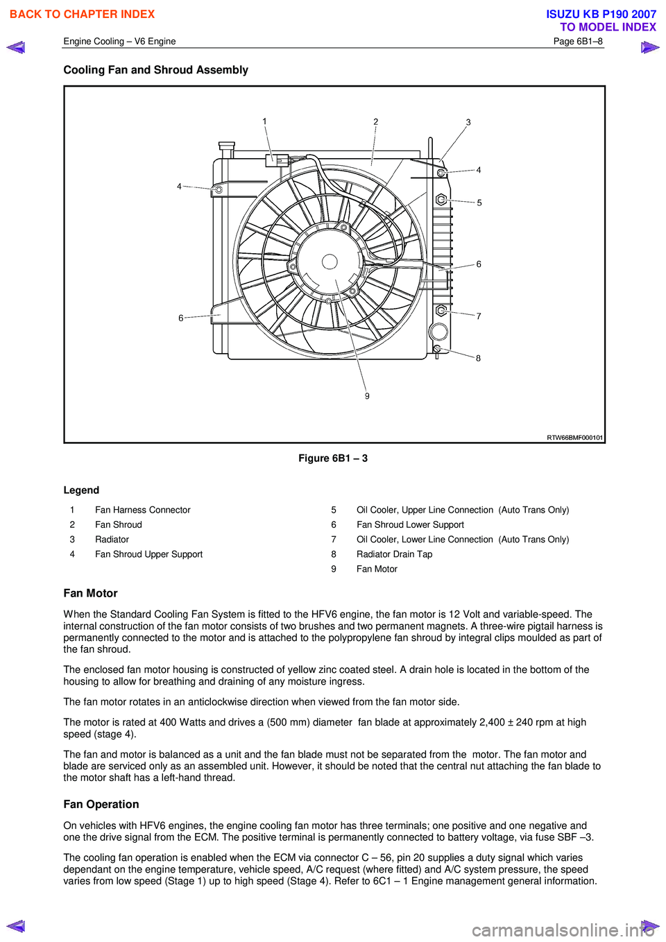
Cooling Fan and Shroud Assembly
Figure 6B1 – 3
Legend
1 Fan Harness Connector
2 Fan Shroud
3 Radiator
4 Fan Shroud Upper Support 5 Oil Cooler, Upper Line Connection (Auto Trans Only)
6 Fan Shroud Lower Support
7 Oil Cooler, Lower Line Connection (Auto Trans Only)
8 Radiator Drain Tap
9 Fan Motor
Fan Motor
W hen the Standard Cooling Fan System is fitted to the HFV6 engine, the fan motor is 12 Volt and variable-speed. The
internal construction of the fan motor consists of two brushes and two permanent magnets. A three-wire pigtail harness is
permanently connected to the motor and is attached to the polypropylene fan shroud by integral clips moulded as part of
the fan shroud.
The enclosed fan motor housing is constructed of yellow zinc coated steel. A drain hole is located in the bottom of the
housing to allow for breathing and draining of any moisture ingress.
The fan motor rotates in an anticlockwise direction when viewed from the fan motor side.
The motor is rated at 400 W atts and drives a (500 mm) diameter fan blade at approximately 2,400 ± 240 rpm at high
speed (stage 4).
The fan and motor is balanced as a unit and the fan blade must not be separated from the motor. The fan motor and
blade are serviced only as an assembled unit. However, it should be noted that the central nut attaching the fan blade to
the motor shaft has a left-hand thread.
Fan Operation
On vehicles with HFV6 engines, the engine cooling fan motor has three terminals; one positive and one negative and
one the drive signal from the ECM. The positive terminal is permanently connected to battery voltage, via fuse SBF –3.
The cooling fan operation is enabled when the ECM via connector C – 56, pin 20 supplies a duty signal which varies
dependant on the engine temperature, vehicle speed, A/C request (where fitted) and A/C system pressure, the speed
varies from low speed (Stage 1) up to high speed (Stage 4). Refer to 6C1 – 1 Engine management general information.
BACK TO CHAPTER INDEX
TO MODEL INDEX
ISUZU KB P190 2007