2007 ISUZU KB P190 belt
[x] Cancel search: beltPage 3136 of 6020
Engine Cooling – V6 Engine Page 6B1–1
Section 6B1
Engine Cooling – V6
ATTENTION
Before performing any Service Operation or other procedure described in this Section, refer to 1.1 WARNING,
CAUTION and NOTES for correct workshop practices with regard to safety and/or property damage.
1 General Information ............................................................................................................ ...................3
1.1 WARNING, CAUTION and NOTES ..................................................................................................... ................... 4
1.2 Definition of WARNING, CAUTION and NOTE Statements ......................................................................... .. 4
WARNING defined ............................................................................................................................................. 4
CAUTION defined .............................................................................................................................................. 4
NOTE defined..................................................................................................................................................... 4
2 General Description ............................................................................................................ ...................5
2.1 Radiator Assembly .............................................................................................................. .................................. 5
2.2 Cooling Fan – Standard Specification.................................................................................................................. 7
Overview ................................................................................................................................................................. 7
Cooling Fan and Shroud Assembly ................................................................................................ .................... 8
Fan Motor ........................................................................................................................................................... 8
Fan Operation .................................................................................................................. .................................. 8
V6 Cooling Fan Wiring Diagram .................................................................................................. ....................... 9
Fan Assembly connector .................................................................................................................................. 10
2.3 Coolant Pump....................................................................................................................................................... 10
2.4 Coolant Outlet Housing ......................................................................................................... .............................. 11
2.5 Thermostat ........................................................................................................................................................... 11
2.6 Coolant Filler Cap ............................................................................................................. ................................... 13
2.7 Coolant Recovery Reservoir ..................................................................................................... .......................... 14
2.8 Engine Coolant Temperature Sensor .............................................................................................. ................... 15
3 Service Operations ...............................................................................................................................16
3.1 Service Notes ....................................................................................................................................................... 16
Safety .................................................................................................................................................................... 16
Periodic Servicing............................................................................................................. ................................... 16
Environmental Issues ........................................................................................................... ............................... 16
3.2 Coolant Maintenance ........................................................................................................................................... 17
Topping Up the Cooling System.................................................................................................. ....................... 18
Testing Coolant Concentration........................................................................................................................... 18
Method 1 – Refractometer................................................................................................................................ 18
Method 2 – Hydrometer.................................................................................................................................... 21
3.3 Draining and Filling Cooling System ............................................................................................ ..................... 22
Draining ................................................................................................................................................................ 22
Filling .................................................................................................................................................................... 22
3.4 Cleaning Cooling System ........................................................................................................ ............................ 25
Cooling System Reverse Flush ................................................................................................... ....................... 25
Radiator............................................................................................................................................................ 25
Engine .............................................................................................................................................................. 26
Heater Hoses and Core.......................................................................................................... .......................... 27
3.5 Drive Belt Tension ............................................................................................................................................... 28
Inspect .................................................................................................................................................................. 29
3.6 Coolant Hoses ...................................................................................................................................................... 30
3.7 Pressure Testing ............................................................................................................... ................................... 31
Coolant Filler Cap Pressure Testing ............................................................................................ ...................... 31
BACK TO CHAPTER INDEX
TO MODEL INDEX
ISUZU KB P190 2007
Page 3145 of 6020
Engine Cooling – V6 Engine Page 6B1–10
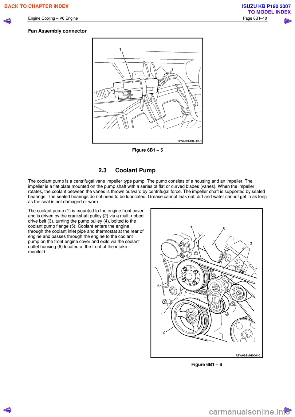
Fan Assembly connector
Figure 6B1 – 5
2.3 Coolant Pump
The coolant pump is a centrifugal vane impeller type pump. The pump consists of a housing and an impeller. The
impeller is a flat plate mounted on the pump shaft with a series of flat or curved blades (vanes). W hen the impeller
rotates, the coolant between the vanes is thrown outward by centrifugal force. The impeller shaft is supported by sealed
bearings. The sealed bearings do not need to be lubricated. Grease cannot leak out, dirt and water cannot get in as long
as the seal is not damaged or worn.
The coolant pump (1) is mounted to the engine front cover
and is driven by the crankshaft pulley (2) via a multi-ribbed
drive belt (3), turning the pump pulley (4), bolted to the
coolant pump flange (5). Coolant enters the engine
through the coolant inlet pipe and thermostat at the rear of
engine and passes through the engine to the coolant
pump on the front engine cover and exits via the coolant
outlet housing (6) located at the front of the intake
manifold.
Figure 6B1 – 6
BACK TO CHAPTER INDEX
TO MODEL INDEX
ISUZU KB P190 2007
Page 3163 of 6020
Engine Cooling – V6 Engine Page 6B1–28
3.5 Drive Belt Tension
An automatic tensioner assembly provides drive belt tension. The tensioner is an idler pulley mounted on a spring-loaded
arm that maintains the drive belt at the proper tension, without imposing undue loads on the various components.
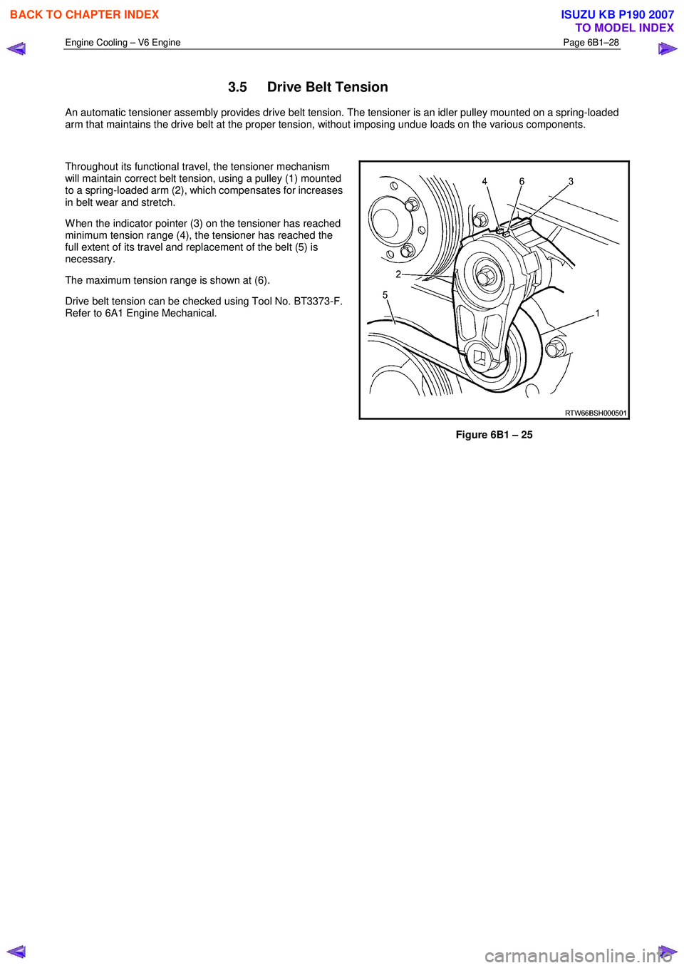
Throughout its functional travel, the tensioner mechanism
will maintain correct belt tension, using a pulley (1) mounted
to a spring-loaded arm (2), which compensates for increases
in belt wear and stretch.
W hen the indicator pointer (3) on the tensioner has reached
minimum tension range (4), the tensioner has reached the
full extent of its travel and replacement of the belt (5) is
necessary.
The maximum tension range is shown at (6).
Drive belt tension can be checked using Tool No. BT3373-F.
Refer to 6A1 Engine Mechanical.
Figure 6B1 – 25
BACK TO CHAPTER INDEX
TO MODEL INDEX
ISUZU KB P190 2007
Page 3164 of 6020
Engine Cooling – V6 Engine Page 6B1–29
Inspect
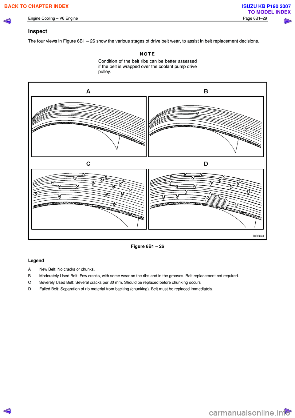
The four views in Figure 6B1 – 26 show the various stages of drive belt wear, to assist in belt replacement decisions.
NOTE
Condition of the belt ribs can be better assessed
if the belt is wrapped over the coolant pump drive
pulley.
Figure 6B1 – 26
Legend
A New Belt: No cracks or c hunks.
B Moderately Used Belt: Few cra cks, with some wear on the ribs and in the grooves. Belt replacement not required.
C Severely Used Belt: Several cracks per 30 mm. S hould be replaced before chunking occurs
D Failed Belt: Separation of rib material from backing (chunking). Belt must be replaced immediately.
BACK TO CHAPTER INDEX
TO MODEL INDEX
ISUZU KB P190 2007
Page 3175 of 6020

Engine Cooling – V6 Engine Page 6B1–40
2 Check coolant recovery system for leaks.
3.10 Coolant Pump
Remove
Refer to 3.1 Service Notes in this Section, for
important safety items.
NOTE
The coolant pump is not to be disassembled and
is replaced only as an assembly.
1 Allow engine to cool to ambient temperature (less than 50 ° C), and then remove the coolant filler cap (located at
the front left-hand side of the engine).
Disconnection of the battery affects certain
vehicle electronic systems. Refer to 1.1
WARNING, CAUTION and NOTES, before
removing the ground lead.
2 Disconnect the battery ground lead. Refer to 8A – Electrical Body & Chassis.
3 Loosen coolant pump pulley to hub bolts (1).
NOTE
While the view shows the drive belt removed,
it will be easier to loosen the four pulley bolts,
with the belt installed.
Figure 6B1 – 42
BACK TO CHAPTER INDEX
TO MODEL INDEX
ISUZU KB P190 2007
Page 3176 of 6020
Engine Cooling – V6 Engine Page 6B1–41
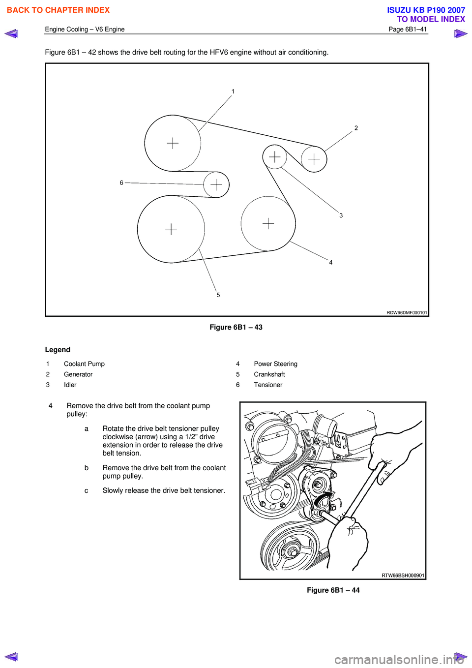
Figure 6B1 – 42 shows the drive belt routing for the HFV6 engine without air conditioning.
Figure 6B1 – 43
Legend
1 Coolant Pump
2 Generator
3 Idler 4 Power Steering
5 Crankshaft
6 Tensioner
4 Remove the drive belt from the coolant pump pulley:
a Rotate the drive belt tensioner pulley clockwise (arrow) using a 1/2” drive
extension in order to release the drive
belt tension.
b Remove the drive belt from the coolant pump pulley.
c Slowly release the drive belt tensioner.
Figure 6B1 – 44
BACK TO CHAPTER INDEX
TO MODEL INDEX
ISUZU KB P190 2007
Page 3179 of 6020
Engine Cooling – V6 Engine Page 6B1–44
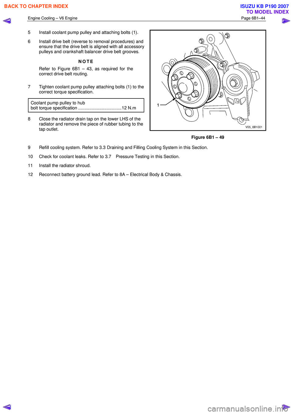
5 Install coolant pump pulley and attaching bolts (1).
6 Install drive belt (reverse to removal procedures) and ensure that the drive belt is aligned with all accessory
pulleys and crankshaft balancer drive belt grooves.
NOTE
Refer to Figure 6B1 – 43, as required for the
correct drive belt routing.
7 Tighten coolant pump pulley attaching bolts (1) to the correct torque specification.
Coolant pump pulley to hub
bolt torque specification ...................................12 N.m
8 Close the radiator drain tap on the lower LHS of the radiator and remove the piece of rubber tubing to the
tap outlet.
Figure 6B1 – 49
9 Refill cooling system. Refer to 3.3 Draining and Filling Cooling System in this Section.
10 Check for coolant leaks. Refer to 3.7 Pressure Testing in this Section.
11 Install the radiator shroud.
12 Reconnect battery ground lead. Refer to 8A – Electrical Body & Chassis.
BACK TO CHAPTER INDEX
TO MODEL INDEX
ISUZU KB P190 2007
Page 3197 of 6020

Engine Cooling – V6 Engine Page 6B1–62
Refer to 3.1 Service Notes in this Section, for
important safety items before removing the
coolant filler pressure cap or servicing the
system.
The cooling system is designed to operate at
120 –
––
–
130 kPa and a maximum temperature
not above 130 °
°°
°
C.
Cooling System Diagnosis
Step Action Result Yes No
1
Check Temperature gauge reading High Temp.
Low Temp. Go to Step 2
Go to Step 6 –
2
Check drive belt condition and tension. Refer to 6A1
Engine Mechanical. To Specification Go to Step 3 Replace drive
belt or
tensioner.
3 Check coolant Boiling Go to Step 4 Go to Step 5
4 Check coolant level. Refer to 3.2 Coolant
Maintenance in this Section. Low Go to Step 10 Go to Step 6
5
Check coolant filler cap. Refer to 3.7 Pressure
Testing – Coolant Filler Cap Pressure Testing in this
Section OK? Go to Step 8
Replace
Coolant filler
cap
6 Check thermostat. Refer to 3.8 Thermostat in this
Section. OK? Go to Step 9 Go to Step 13
7
Check Engine Coolant Temperature (ECT) sensor.
Refer to 6C1 Engine Management General Information. Faulty Replace Go to Step 12
8
Check cooling fan operation. Refer to 6C1 Engine
Management General Information. Operational Go to Step 10 Repair
9
Check for collapsed upper or lower radiator hose. Collapsed Replace Go to Step 13
10 Visual system check Leaks Go to Step 13 Go to Step 11
11 Check coolant concentration. Refer to 3.2 Coolant
Maintenance. To Specification Go to Step 12 Correct
Concentration Level
12 Check radiator core for bent fins, dirt, bugs or other
obstructions. Obstructed Clean or
straighten Go to Step 14
13
Pressure Test cooling system. Refer to 3.7 Pressure
Testing in this Section. Leaks Repair System OK
14
If none of the above require repair, the problem is
complex or of a major nature.
Refer to 4.5 Problems Not Requiring Disassembly of
Cooling System or 4.6 Problems Requiring Disassembly
of Cooling System. – – –
BACK TO CHAPTER INDEX
TO MODEL INDEX
ISUZU KB P190 2007