2007 ISUZU KB P190 belt
[x] Cancel search: beltPage 5678 of 6020
SUPPLEMENTAL RESTRAINT SYSTEM 9A-43
Pretensioner Seat Belt (If so equipped)
Service Precaution
WARNING: WHEN PERFORMING SERVICE ON OR
AROUND THE PRETENSIONER SEAT BELT OR
THE PRETENSIONER SEAT BELT WIRING,
FOLLOW THE PROCEDURES LISTED BELOW TO
TEMPORARILY DISABLE THE PRETENSIONER
SEAT BELT.
FAILURE TO FOLLOW PROCEDURES COULD
RESULT IN POSSIBLE THE PRETENSIONER SEAT
BELT DEPLOYMENT, PERSONAL INJURY OR
OTHERWISE UNNEEDED THE PRETENSIONER
SEAT BELT REPAIR.
AS A PRECAUTION, WEAR GLOVES AND SAFETY
GLASSES WHEN PERFORMING THE
PRETENSIONER SEAT BELT. WHEN DEPLOY
A
LIVE PRETENSIONER SEAT BELT AT OUTSIDE
THE
VEHICLE, DEPLOYMENT HARNESS SHALL
REMAIN SHORTED AND NOT BE CONNECTED TO
A POWER SOURCE UNTIL THE PRETENSIONER
SEAT BELT IS TO BE DEPLOYED. THE
PRETENSIONER SEAT BELT WILL IMMEDIATELY
DEPLOY WHEN A POWER SOURCE IS
CONNECTED TO IT. CONNECTING THE
DEPLOYMENT HARNESS SHOULED ALWAYS BE
THE FINAL STEP IN THE PRETENSIONER SEAT
BELT DEPLOYMENT PROCEDURE. FAILURE TO
FOLLOW PROCEDURES IN THE ORDER LISTED
COULD RESULT IN PERSONAL INJURY.
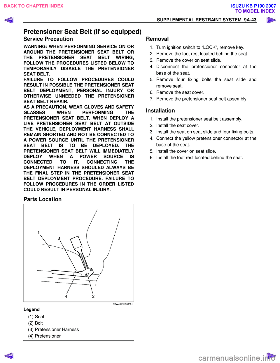
Parts Location
RTW 49JSH000301
Legend
(1) Seat
(2) Bolt
(3) Pretensioner Harness
(4) Pretensioner
Removal
1. Turn ignition switch to “LOCK”, remove key.
2. Remove the foot rest located behind the seat.
3. Remove the cover on seat slide.
4. Disconnect the pretensioner connector at the base of the seat.
5. Remove four fixing bolts the seat slide and remove seat.
6. Remove the seat cover.
7. Remove the pretensioner seat belt assembly.
Installation
1. Install the pretensioner seat belt assembly.
2. Install the seat cover.
3. Install the seat on seat slide and four fixing bolts.
4. Connect the yellow pretensioner connector at the base of the seat.
5. Install the cover on seat slide.
6. Install the foot rest located behind the seat.
BACK TO CHAPTER INDEX TO MODEL INDEXISUZU KB P190 2007
Page 5687 of 6020
RESTRAINT CONTROL SYSTEM 9A1-5
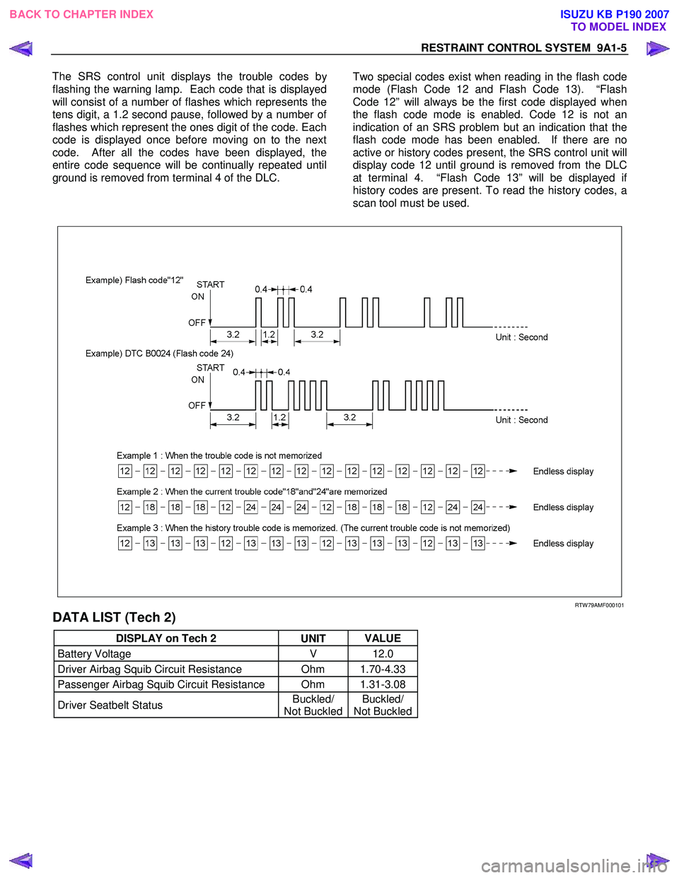
The SRS control unit displays the trouble codes b
y
flashing the warning lamp. Each code that is displayed
will consist of a number of flashes which represents the
tens digit, a 1.2 second pause, followed by a number o
f
flashes which represent the ones digit of the code. Each
code is displayed once before moving on to the next
code. After all the codes have been displayed, the
entire code sequence will be continually repeated until
ground is removed from terminal 4 of the DLC.
Two special codes exist when reading in the flash code
mode (Flash Code 12 and Flash Code 13). “Flash
Code 12” will always be the first code displayed when
the flash code mode is enabled. Code 12 is not an
indication of an SRS problem but an indication that the
flash code mode has been enabled. If there are no
active or history codes present, the SRS control unit will
display code 12 until ground is removed from the DLC
at terminal 4. “Flash Code 13” will be displayed i
f
history codes are present. To read the history codes, a
scan tool must be used.
RTW 79AMF000101
DATA LIST (Tech 2)
DISPLAY on Tech 2 UNIT VALUE
Battery Voltage
V 12.0
Driver Airbag Squib Circuit Resistance Ohm 1.70-4.33
Passenger Airbag Squib Circuit Resistance Ohm 1.31-3.08
Driver Seatbelt Status Buckled/
Not Buckled Buckled/
Not Buckled
BACK TO CHAPTER INDEX
TO MODEL INDEX
ISUZU KB P190 2007
Page 5746 of 6020
9A1-64 RESTRAINT CONTROL SYSTEM
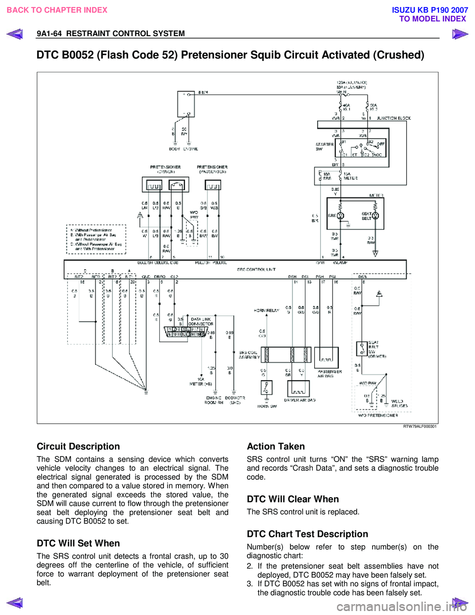
DTC B0052 (Flash Code 52) Pretensioner Squib Circuit Activated (Crushed)
RTW 79ALF000301
Circuit Description
The SDM contains a sensing device which converts
vehicle velocity changes to an electrical signal. The
electrical signal generated is processed by the SDM
and then compared to a value stored in memory. W hen
the generated signal exceeds the stored value, the
SDM will cause current to flow through the pretensione
r
seat belt deploying the pretensioner seat belt and
causing DTC B0052 to set.
DTC Will Set When
The SRS control unit detects a frontal crash, up to 30
degrees off the centerline of the vehicle, of sufficient
force to warrant deployment of the pretensioner seat
belt.
Action Taken
SRS control unit turns “ON” the “SRS” warning lamp
and records “Crash Data”, and sets a diagnostic trouble
code.
DTC Will Clear When
The SRS control unit is replaced.
DTC Chart Test Description
Number(s) below refer to step number(s) on the
diagnostic chart:
2. If the pretensioner seat belt assemblies have not deployed, DTC B0052 may have been falsely set.
3. If DTC B0052 has set with no signs of frontal impact, the diagnostic trouble code has been falsely set.
BACK TO CHAPTER INDEX TO MODEL INDEX
ISUZU KB P190 2007
Page 5747 of 6020
RESTRAINT CONTROL SYSTEM 9A1-65
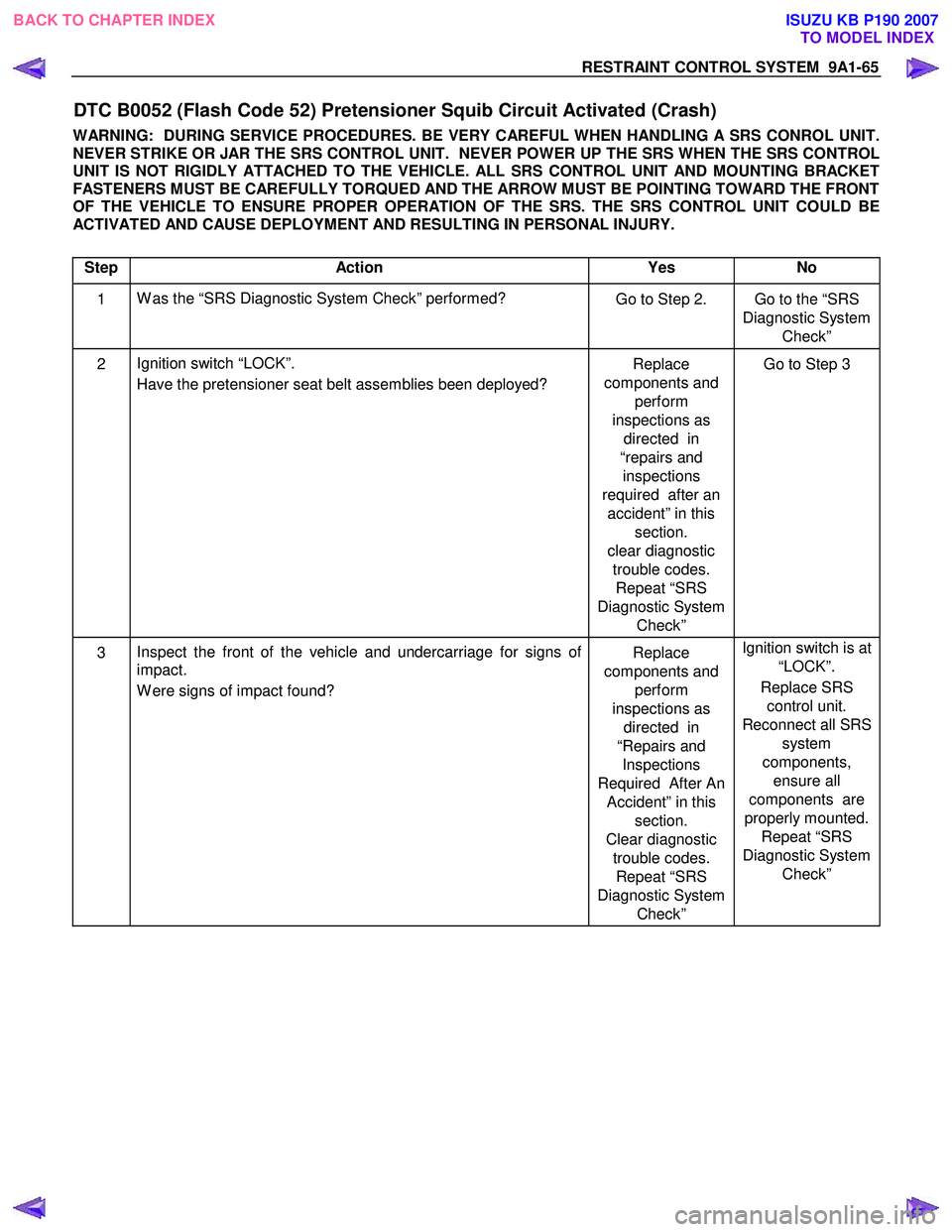
DTC B0052 (Flash Code 52) Pretensioner Squib Circuit Activated (Crash)
WARNING: DURING SERVICE PROCEDURES. BE VERY CAREFUL WHEN HANDLING A SRS CONROL UNIT.
NEVER STRIKE OR JAR THE SRS CONTROL UNIT. NEVER POWER UP THE SRS WHEN THE SRS CONTROL
UNIT IS NOT RIGIDLY ATTACHED TO THE VEHICLE. ALL SRS CONTROL UNIT AND MOUNTING BRACKET
FASTENERS MUST BE CAREFULLY TORQUED AND THE ARROW MUST BE POINTING TOWARD THE FRONT
OF THE VEHICLE TO ENSURE PROPER OPERATION OF THE SRS. THE SRS CONTROL UNIT COULD BE
ACTIVATED AND CAUSE DEPLOYMENT AND RESULTING IN PERSONAL INJURY.
Step Action Yes No
1 W as the “SRS Diagnostic System Check” performed?
Go to Step 2. Go to the “SRS
Diagnostic System Check”
2 Ignition switch “LOCK”.
Have the pretensioner seat belt assemblies been deployed? Replace
components and perform
inspections as directed in
“repairs and inspections
required after an accident” in this section.
clear diagnostic trouble codes. Repeat “SRS
Diagnostic System Check” Go to Step 3
3
Inspect the front of the vehicle and undercarriage for signs of
impact.
W ere signs of impact found? Replace
components and perform
inspections as directed in
“Repairs and Inspections
Required After An Accident” in this section.
Clear diagnostic trouble codes. Repeat “SRS
Diagnostic System Check” Ignition switch is at
“LOCK”.
Replace SRS control unit.
Reconnect all SRS system
components, ensure all
components are
properly mounted. Repeat “SRS
Diagnostic System Check”
BACK TO CHAPTER INDEX TO MODEL INDEX
ISUZU KB P190 2007
Page 5759 of 6020
CAB 10-1
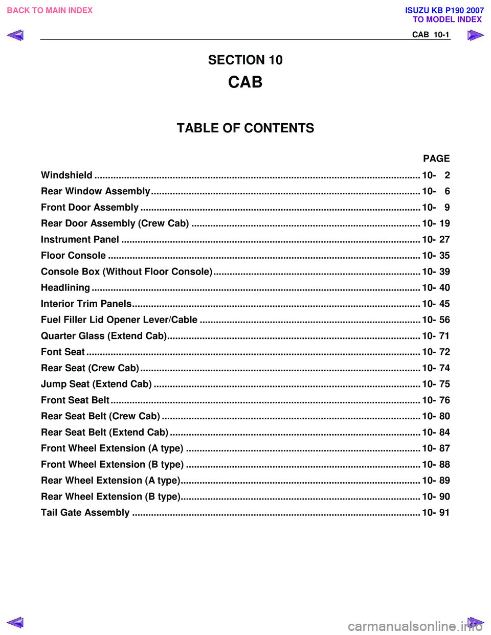
SECTION 10
CAB
TABLE OF CONTENTS
PAGE
Windshield ..................................................................................................................... .... 10- 2
Rear Window Assembly .................................................................................................... 10- 6
Front Door Assembly ........................................................................................................ 10- 9
Rear Door Assembly (Crew Cab) ..................................................................................... 10- 19
Instrument Panel ............................................................................................................... 10- 27
Floor Console .................................................................................................................. .. 10- 35
Console Box (Without Floor Console) ............................................................................. 10- 39
Headlining ..................................................................................................................... ..... 10- 40
Interior Trim Panels ........................................................................................................... 10- 45
Fuel Filler Lid Opener Lever/Cable .................................................................................. 10- 56
Quarter Glass (Extend Cab).............................................................................................. 10- 71
Font Seat ...................................................................................................................... ...... 10- 72
Rear Seat (Crew Cab) ........................................................................................................ 10- 74
Jump Seat (Extend Cab) ................................................................................................... 10- 75
Front Seat Belt ................................................................................................................ ... 10- 76
Rear Seat Belt (Crew Cab) ................................................................................................ 10- 80
Rear Seat Belt (Extend Cab) ............................................................................................. 10- 84
Front Wheel Extension (A type) ....................................................................................... 10- 87
Front Wheel Extension (B type) ....................................................................................... 10- 88
Rear Wheel Extension (A type)......................................................................................... 10- 89
Rear Wheel Extension (B type)......................................................................................... 10- 90
Tail Gate Assembly ........................................................................................................... 10 - 91
TO MODEL INDEX
BACK TO MAIN INDEX
ISUZU KB P190 2007
Page 5803 of 6020
CAB 10-45
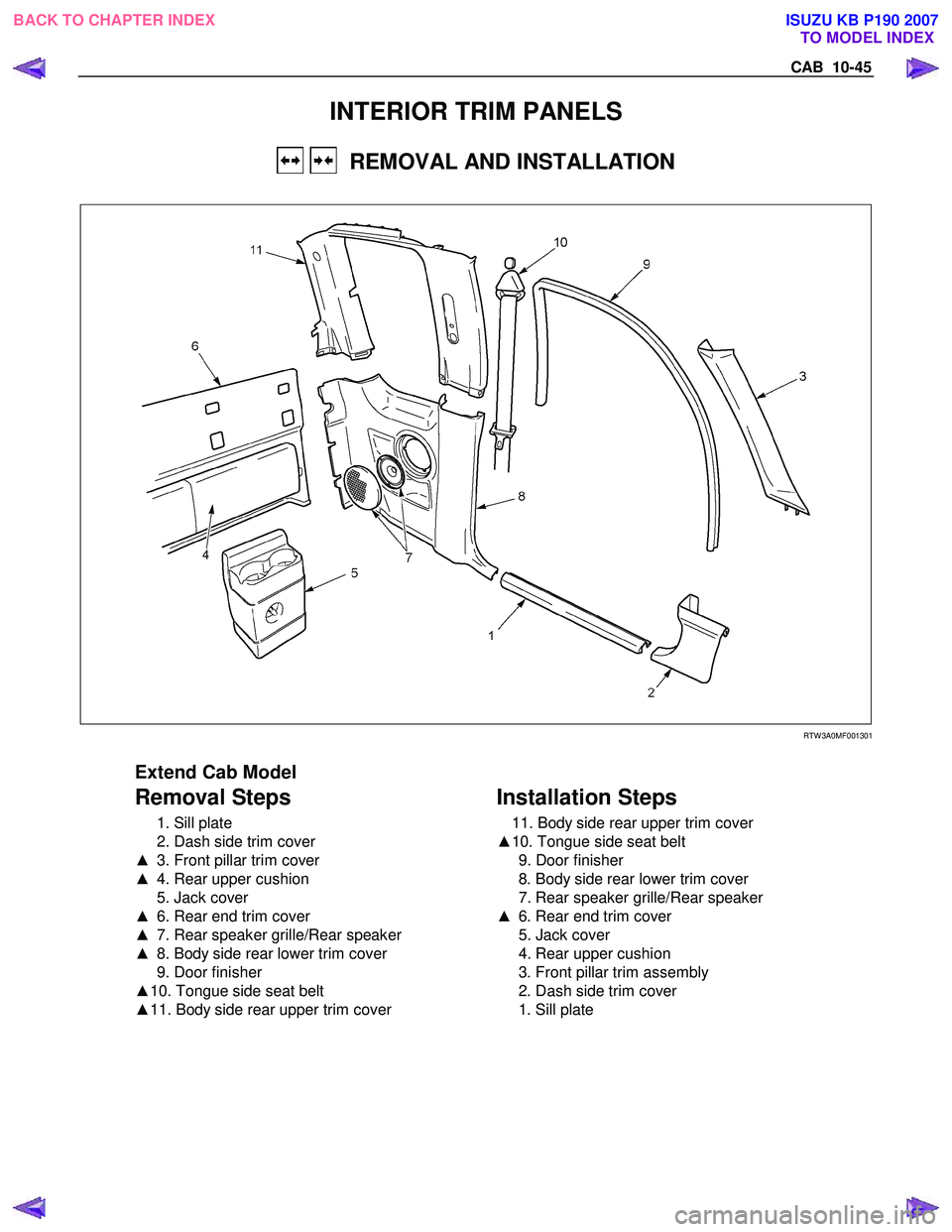
INTERIOR TRIM PANELS
REMOVAL AND INSTALLATION
RTW 3A0MF001301
Extend Cab Model
Removal Steps
1. Sill plate
2. Dash side trim cover
▲ 3. Front pillar trim cover
▲ 4. Rear upper cushion
5. Jack cover
▲ 6. Rear end trim cover
▲ 7. Rear speaker grille/Rear speaker
▲ 8. Body side rear lower trim cover
9. Door finisher
▲ 10. Tongue side seat belt
▲ 11. Body side rear upper trim cover
Installation Steps
11. Body side rear upper trim cover
▲ 10. Tongue side seat belt
9. Door finisher
8. Body side rear lower trim cover
7. Rear speaker grille/Rear speaker
▲ 6. Rear end trim cover
5. Jack cover
4. Rear upper cushion
3. Front pillar trim assembly
2. Dash side trim cover
1. Sill plate
BACK TO CHAPTER INDEX TO MODEL INDEX
ISUZU KB P190 2007
Page 5805 of 6020
CAB 10-47
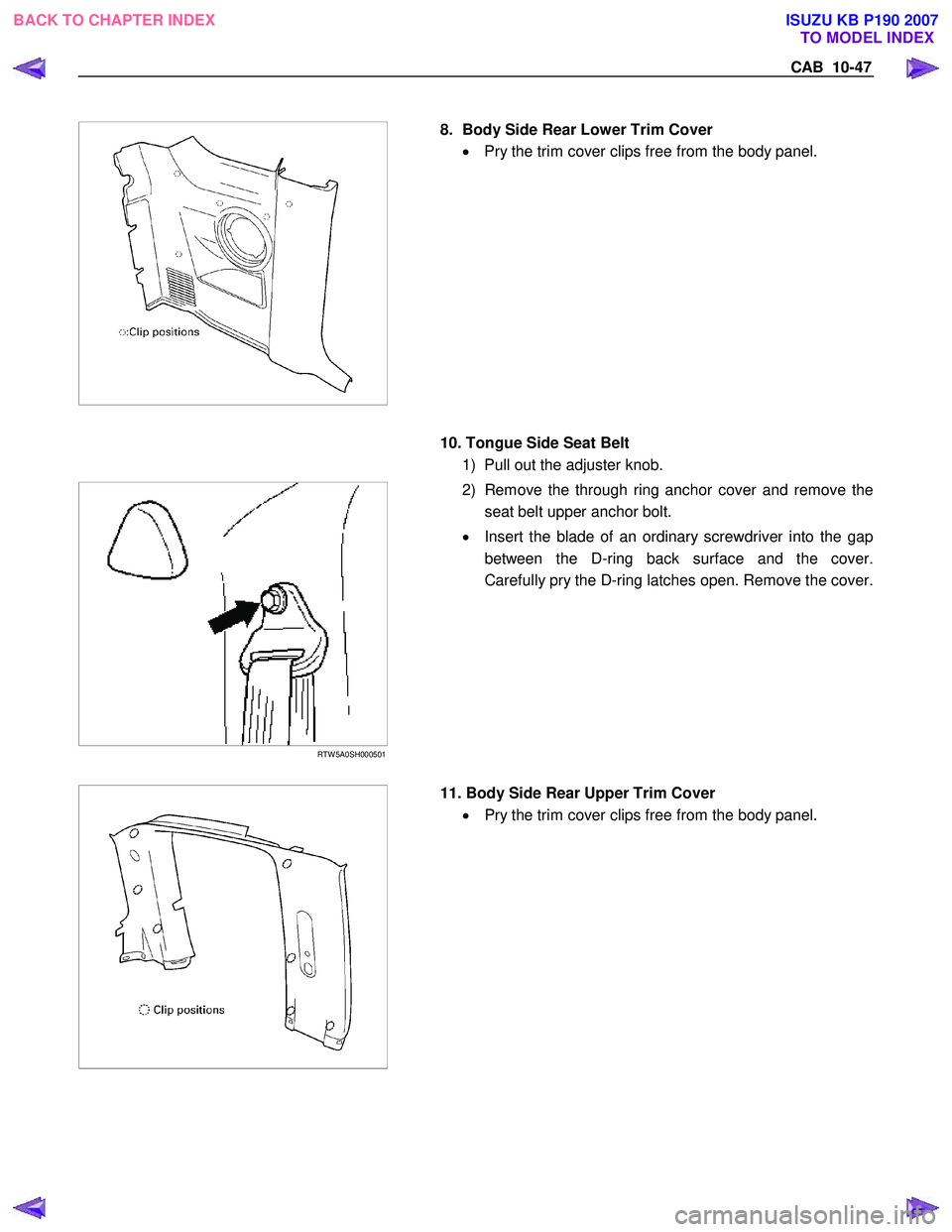
8. Body Side Rear Lower Trim Cover
• Pry the trim cover clips free from the body panel.
10. Tongue Side Seat Belt
1) Pull out the adjuster knob.
RTW 5A0SH000501
2) Remove the through ring anchor cover and remove the
seat belt upper anchor bolt.
• Insert the blade of an ordinary screwdriver into the gap
between the D-ring back surface and the cover.
Carefully pry the D-ring latches open. Remove the cover.
11. Body Side Rear Upper Trim Cover
• Pry the trim cover clips free from the body panel.
BACK TO CHAPTER INDEX
TO MODEL INDEX
ISUZU KB P190 2007
Page 5806 of 6020
10-48 CAB
Important Operations - Installation
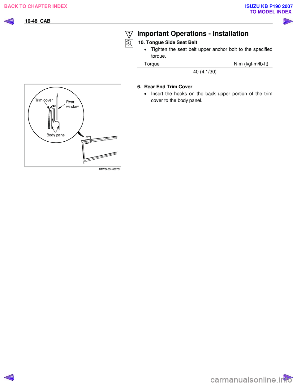
10. Tongue Side Seat Belt • Tighten the seat belt upper anchor bolt to the specified
torque.
Torque N ⋅m (kgf ⋅m/lb ⋅ft)
40 (4.1/30)
RTW 5A0SH000701
6. Rear End Trim Cover
• Insert the hooks on the back upper portion of the trim
cover to the body panel.
BACK TO CHAPTER INDEX TO MODEL INDEX
ISUZU KB P190 2007