2007 ISUZU KB P190 belt
[x] Cancel search: beltPage 5303 of 6020
ELECTRICAL-BODY AND CHASSIS 8A-365
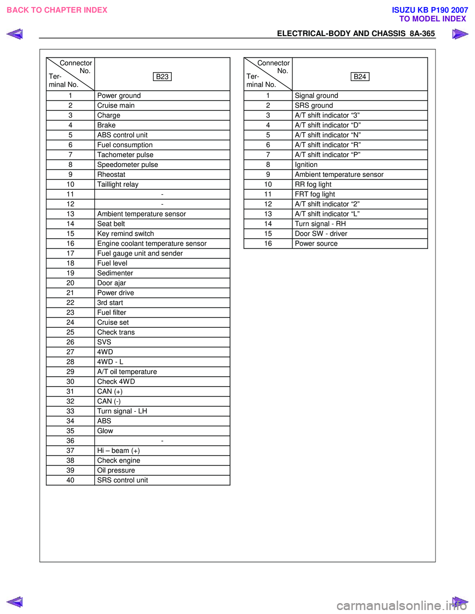
Connector
Ter- No.
minal No.
B23
1 Power ground
2 Cruise main
3 Charge
4 Brake
5 ABS control unit
6 Fuel consumption
7 Tachometer pulse
8 Speedometer pulse
9 Rheostat
10 Taillight relay
11 -
12 -
13 Ambient temperature sensor
14 Seat belt
15 Key remind switch
16 Engine coolant temperature sensor
17 Fuel gauge unit and sender
18 Fuel level
19 Sedimenter
20 Door ajar
21 Power drive
22 3rd start
23 Fuel filter
24 Cruise set
25 Check trans
26 SVS
27 4W D
28 4W D - L
29 A/T oil temperature
30 Check 4W D
31 CAN (+)
32 CAN (-)
33 Turn signal - LH
34 ABS
35 Glow
36 -
37 Hi – beam (+)
38 Check engine
39 Oil pressure
40 SRS control unit
Connector
Ter- No.
minal No.
B24
1 Signal ground
2 SRS ground
3 A/T shift indicator “3”
4 A/T shift indicator “D”
5 A/T shift indicator “N”
6 A/T shift indicator “R”
7 A/T shift indicator “P”
8 Ignition
9 Ambient temperature sensor
10 RR fog light
11 FRT fog light
12 A/T shift indicator “2”
13 A/T shift indicator “L”
14 Turn signal - RH
15 Door SW - driver
16 Power source
BACK TO CHAPTER INDEX TO MODEL INDEXISUZU KB P190 2007
Page 5304 of 6020
8A-366 ELECTRICAL-BODY AND CHASSIS
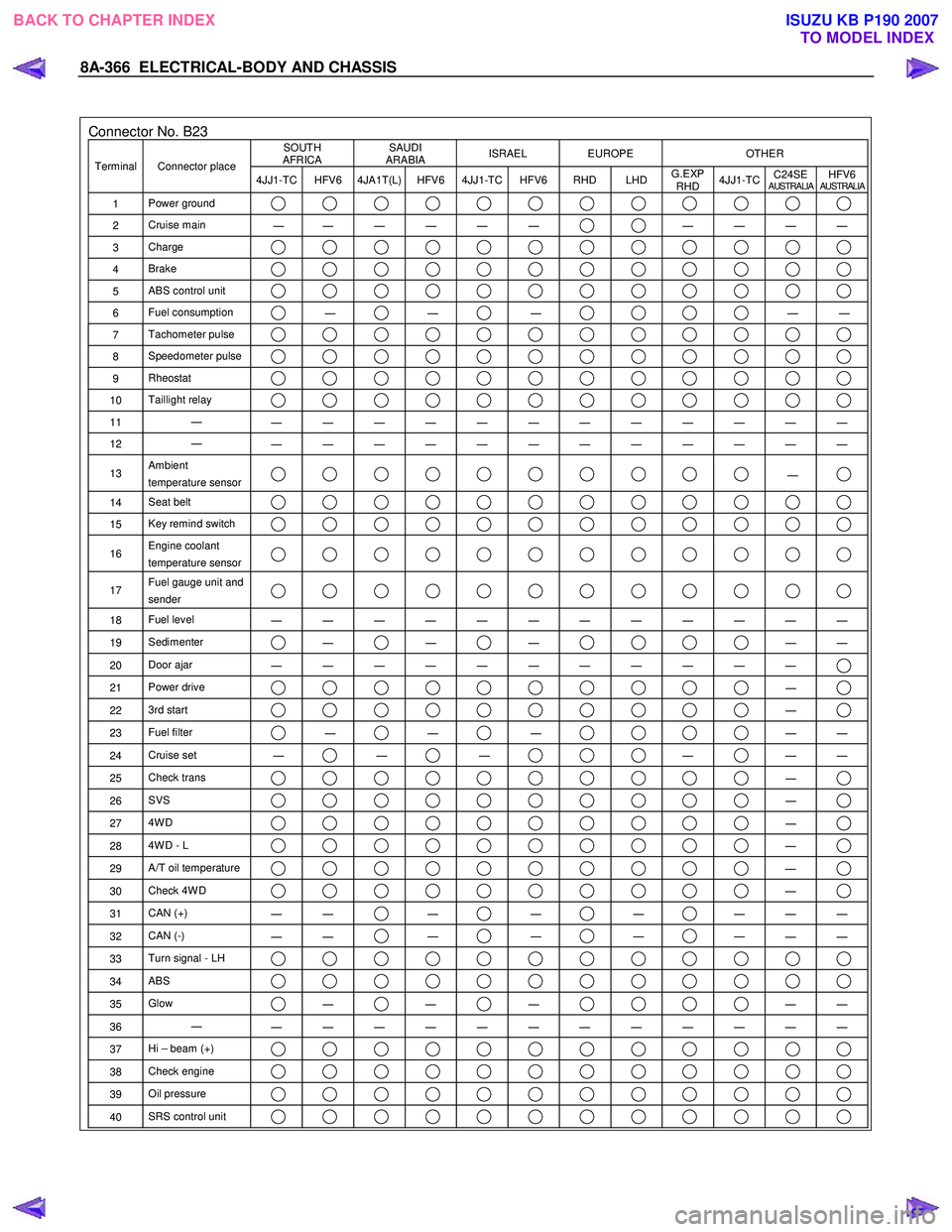
Connector No. B23 SOUTH
AFRICA SAUDI
ARABIA ISRAEL EUROPE OTHER
Terminal Connector place
4JJ1-TC HFV6 4JA1T(L) HFV6 4JJ1-TC HFV6 RHD LHD G.EXP
RHD 4JJ1-TC
C24SE
AUSTRALIAHFV6AUSTRALIA
1
Power ground
2 Cruise main
―
― ― ― ― ― ― ― ― ―
3
Charge
4 Brake
5 ABS control unit
6 Fuel consumption ―
―
―
―
―
7 Tachometer pulse
8 Speedometer pulse
9 Rheostat
10 Taillight relay
11 ―
― ― ― ― ― ― ― ― ― ― ― ―
12 ―
― ― ― ― ― ― ― ― ― ― ― ―
13 Ambient
temperature sensor ―
14 Seat belt
15 Key remind switch
16 Engine coolant
temperature sensor
17 Fuel gauge unit and
sender
18 Fuel level
― ― ― ― ― ― ― ― ― ― ― ―
19 Sedimenter ―
―
―
―
―
20 Door ajar
― ― ― ― ― ― ― ― ― ― ―
21 Power drive ―
22 3rd start ―
23 Fuel filter ―
―
―
―
―
24 Cruise set
― ―
―
―
―
―
25 Check trans ―
26 SVS ―
27 4W D ―
28 4W D - L ―
29 A/T oil temperature ―
30 Check 4W D ―
31 CAN (+)
― ― ―
―
―
― ― ―
32
CAN (-)
― ― ―
―
―
― ― ―
33
Turn signal - LH
34 ABS
35 Glow ―
―
―
―
―
36 ―
― ― ― ― ― ― ― ― ― ― ― ―
37 Hi – beam (+)
38 Check engine
39 Oil pressure
40 SRS control unit
BACK TO CHAPTER INDEX
TO MODEL INDEXISUZU KB P190 2007
Page 5569 of 6020
ELECTRICAL-BODY AND CHASSIS 8A-631
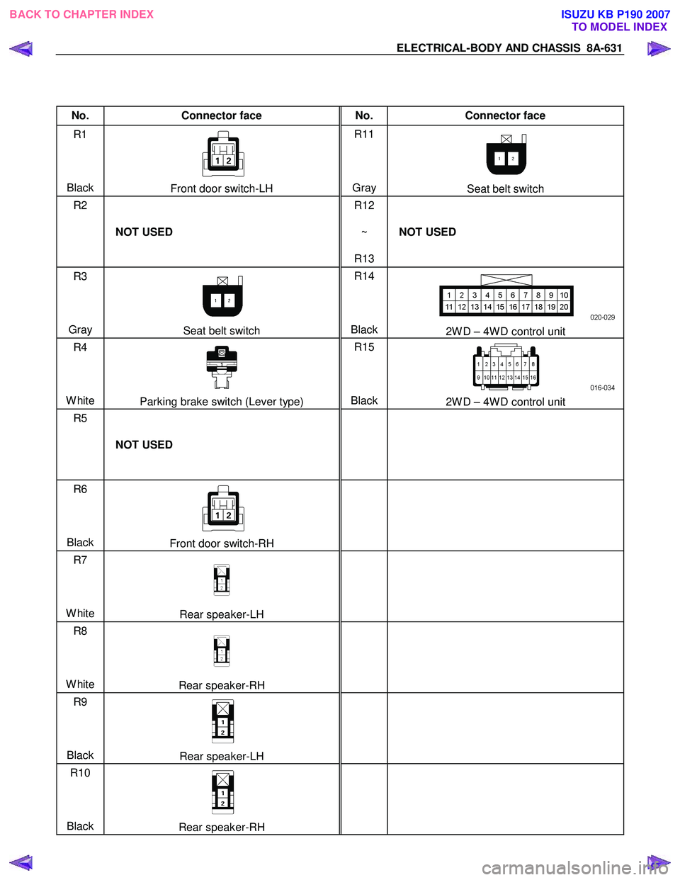
No. Connector face No. Connector face
R1
Black
Front door switch-LH R11
Gray Seat belt switch
R2
NOT USED R12
~
R13 NOT USED
R3
Gray
Seat belt switch R14
Black2W D – 4W D control unit
R4
White
Parking brake switch (Lever type) R15
Black2W D – 4W D control unit
R5
NOT USED
R6
Black
Front door switch-RH
R7
White
Rear speaker-LH
R8
White
Rear speaker-RH
R9
Black
Rear speaker-LH
R10
Black
Rear speaker-RH
BACK TO CHAPTER INDEX
TO MODEL INDEXISUZU KB P190 2007
Page 5638 of 6020
SUPPLEMENTAL RESTRAINT SYSTEM 9A-3
PAGE
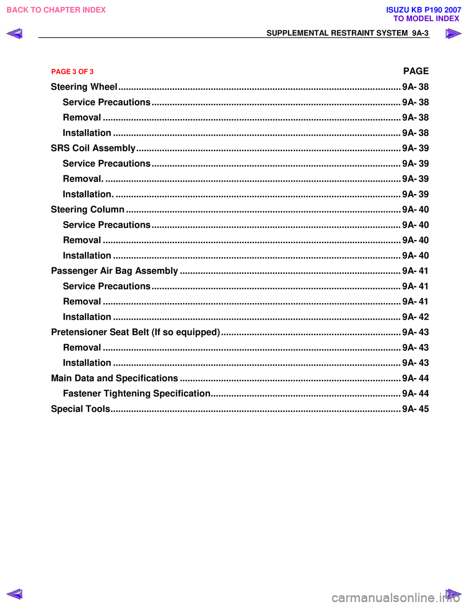
Steering Wheel .............................................................................................................. 9A- 38
Service Precautions ................................................................................................. 9A- 38
Removal .................................................................................................................... 9A- 38
Installation ................................................................................................................ 9A- 38
SRS Coil Assembly ....................................................................................................... 9A- 39 Service Precautions ................................................................................................. 9A- 39
Removal. ................................................................................................................... 9A- 39
Installation. ............................................................................................................... 9A- 39
Steering Column ........................................................................................................... 9A- 4 0
Service Precautions ................................................................................................. 9A- 40
Removal .................................................................................................................... 9A- 40
Installation ................................................................................................................ 9A- 40
Passenger Air Bag Assembly ...................................................................................... 9A- 41 Service Precautions ................................................................................................. 9A- 41
Removal .................................................................................................................... 9A- 41
Installation ................................................................................................................ 9A- 42
Pretensioner Seat Belt (If so equipped) ...................................................................... 9A- 43 Removal .................................................................................................................... 9A- 43
Installation ................................................................................................................ 9A- 43
Main Data and Specifications ...................................................................................... 9A- 44 Fastener Tightening Specification.......................................................................... 9A- 44
Special Tools................................................................................................................. 9 A- 45
PAGE 3 OF 3
BACK TO CHAPTER INDEX TO MODEL INDEXISUZU KB P190 2007
Page 5639 of 6020
9A-4 SUPPLEMENTAL RESTRAINT SYSTEM
Service Precaution
WARNING: THIS VEHICLE HAS A SUPPLEMENTAL
RESTRAINT SYSTEM (SRS). REFER TO THE SRS
COMPONENT AND WIRING LOCATION VIEW IN
ORDER TO DETERMINE WHETHER YOU ARE
PERFORMING A SERVICE ON, OR NEAR, THE SRS
COMPONENTS OR THE SRS WIRING. WHEN YOU
ARE PERFORMING A SERVICE ON OR NEAR THE
SRS COMPONENTS OR THE SRS WIRING, REFER
TO THE SRS SERVICE INFORMATION. FAILURE
TO FOLLOW WARNINGS COULD RESULT IN
POSSIBLE AIR BAG DEPLOYMENT, PERSONAL
INJURY, OR OTHERWISE UNNECESSARY SRS
SYSTEM REPAIRS.
CAUTION: Always use the correct fastener in the
proper location. When you replace a fastener, use
ONLY the exact part number for that application.
ISUZU/GM will call out those fasteners that require
a replacement after removal. ISUZU/GM will also
call out the fasteners that require thread lockers o
r
thread sealant. UNLESS OTHERWISE SPECIFIED,
do not use supplemental coatings (paints,
greases, or other corrosion inhibitors) on threaded
fasteners or fastener joint interfaces. Generally,
such coatings adversely affect the fastener torque
and the joint clamping force, and may damage the
fastener. When you install fasteners, use the
correct tightening sequence and specifications.
Following these instructions can help you avoid
damage to parts and systems.
General Description
CAUTION: When fasteners are removed, always
reinstall them at the same location from which
they were removed. If a fastener needs to be
replaced, use the correct part number fastener fo
r
that application. If the correct part numbe
r
fastener is not available, a fastener of equal size
and strength (or stronger) may be used.
Fasteners that are not reused, and those requiring
thread locking compound will be called out. The
correct torque value must be used when installing
fasteners that require it. If the above conditions
are not followed, parts or system damage could
result.
Restraint Devices
RTW 79ASH000801
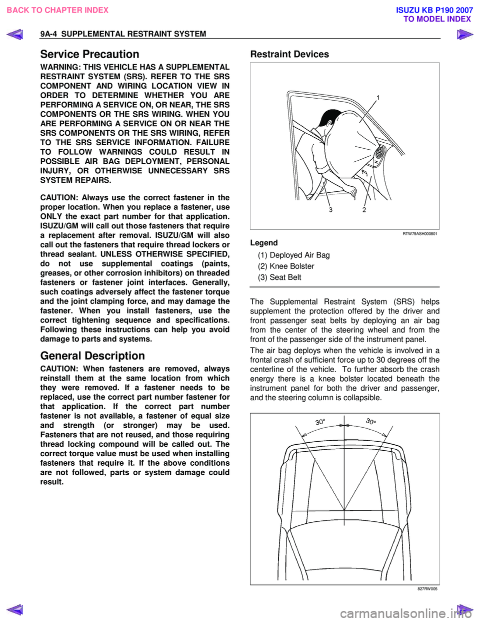
Legend
(1) Deployed Air Bag
(2) Knee Bolster
(3) Seat Belt
The Supplemental Restraint System (SRS) helps
supplement the protection offered by the driver and
front passenger seat belts by deploying an air bag
from the center of the steering wheel and from the
front of the passenger side of the instrument panel.
The air bag deploys when the vehicle is involved in a
frontal crash of sufficient force up to 30 degrees off the
centerline of the vehicle. To further absorb the crash
energy there is a knee bolster located beneath the
instrument panel for both the driver and passenger,
and the steering column is collapsible.
827RW 005
BACK TO CHAPTER INDEX TO MODEL INDEXISUZU KB P190 2007
Page 5651 of 6020
9A-16 SUPPLEMENTAL RESTRAINT SYSTEM
RTW 79ASH000201
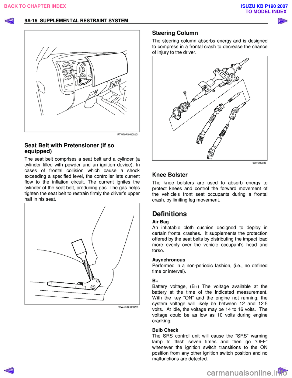
Seat Belt with Pretensioner (If so
equipped)
The seat belt comprises a seat belt and a cylinder (a
cylinder filled with powder and an ignition device). In
cases of frontal collision which cause a shock
exceeding a specified level, the controller lets current
flow to the inflation circuit. The current ignites the
cylinder of the seat belt, producing gas. The gas helps
tighten the seat belt to restrain firmly the driver’s uppe
r
half in his seat.
RTW 49JSH000201
Steering Column
The steering column absorbs energy and is designed
to compress in a frontal crash to decrease the chance
of injury to the driver.
060R300038
Knee Bolster
The knee bolsters are used to absorb energy to
protect knees and control the forward movement o
f
the vehicle's front seat occupants during a frontal
crash, by limiting leg movement.
Definitions
Air Bag
An inflatable cloth cushion designed to deploy in
certain frontal crashes. It supplements the protection
offered by the seat belts by distributing the impact load
more evenly over the vehicle occupant's head and
torso.
Asynchronous
Performed in a non-periodic fashion, (i.e., no defined
time or interval).
B+
Battery voltage, (B+) The voltage available at the
battery at the time of the indicated measurement.
W ith the key “ON” and the engine not running, the
system voltage will likely be between 12 and 12.5
volts. At idle, the voltage may be 14 to 16 volts. The
voltage could be as low as 10 volts during engine
cranking.
Bulb Check
The SRS control unit will cause the “SRS” warning
lamp to flash seven times and then go “OFF”
whenever the ignition switch transitions to the ON
position from any other ignition switch position and no
malfunctions are detected.
BACK TO CHAPTER INDEX TO MODEL INDEXISUZU KB P190 2007
Page 5655 of 6020
9A-20 SUPPLEMENTAL RESTRAINT SYSTEM
Repairs And Inspections Required
After An Accident
If any SRS components are damaged, they must be
replaced. If SRS component mounting points are
damaged, they must be replaced.
• Never use SRS parts from another vehicle. This does not include remanufactured parts purchased
from an authorized dealer; they may be used fo
r
SRS repairs.
• Do not attempt to service the SRS control unit, the SRS coil assembly, or the air bag assembly.
Service of these items is by replacement only.
• Verify the part number of the replacement air bag assembly.
CAUTION: Never use the air bag assembly from
another vehicle or different model year air bag
assembly.
Use only a new air bag assembly matched to the
TFR/S which is being repaired.
CAUTION: Proper operation of the sensors and
supplemental restraint system (SRS) requires that
any repairs to the vehicle structure return it to the
original production configuration. Deployment
requires, at a minimum, replacement of the SRS
control unit, air bag assembly and dimensional
inspection of the steering column. Any visible
damage to the SRS control unit mounting bracket
(s) requires replacement, and the steering column
must be dimensionally inspected, whethe
r
deployment occurred or not.
Accident With Deployment – Component
Replacement And Inspections
Certain SRS components must be replaced or
inspected for damage after a frontal crash involving air
bag deployment. Those components are:
• Air bag assembly
• SRS control unit
CAUTION: Refer to “SRS control unit Replacement
Guidelines” below for important information on
SRS control unit replacement in both deployment
and non-deployment crashes.
• SRS coil assembly — Inspect wiring and connecto
r
for any signs of scorching, melting, or damage due
to excessive heat. Replace if damaged. Refer to
section “SRS Coil Assembly” in this manual.
Accident With or Without Deployment –
Component Inspection
Certain SRS system components and rotation parts
must be inspected after any crash, whether the air bag
has been deployed or not. Those components are:
• Steering column — Refer to Inspection Required “After an Accident” in this manual.
• Knee bolsters and mounting points — Inspect fo
r
any distortion, bending, cracking, or other damage.
• I/P steering column reinforcement plate — Inspect for any distortion, bending, cracking, or othe
r
damage.
• I/P braces — Inspect for any distortion, bending, cracking, or other damage.
• Seat belts and mounting points — Refer to “Seat Belts” in Section “Seat Belt” of this workshop
manual.
SRS Control Unit Replacement Guidelines
SRS control unit replacement policy requires
replacement of the SRS control unit after a crash
involving air bag deployment when the “SRS W arning
Lamp” turned “ON”, the “SRS Diagnosis” should be
done according to Section “Restraint Control System.”
Wiring Damage
If any SRS wire harness is damaged, it should be
replaced. Don't repair the SRS harness. It is
replacement only.
SRS Connector (Plastic Body And
Terminal Metal Pin) Damage
If any connector or terminal in the SRS wire harness
(except pigtails) is damaged, it should be replaced.
SRS Wire Pigtail Damage
If the wiring pigtail (a wire or wires attached directly to
the device, not by a connector) is damaged, the entire
component (with pigtail) must be replaced. Examples
of “pigtail” components are the driver air bag
assembly, the passenger air bag assembly, and the
SRS coil assembly.
BACK TO CHAPTER INDEX TO MODEL INDEXISUZU KB P190 2007
Page 5668 of 6020
SUPPLEMENTAL RESTRAINT SYSTEM 9A-33
Inspections Required After An Accident
CAUTION: Certain SRS components must be
replaced after a frontal crash involving air bag
deployment.
In all types of accidents regardless of “Air Bag”
deployment, visually inspect all of the following
components and replace as required:
– Driver air bag assembly
– Passenger air bag assembly
– Steering wheel
– SRS coil assembly
– Steering column
– Knee bolster and instrument panel mounting attachments
– Driver seat and belt
– Passenger seat and belt
– SRS control unit
The SRS control unit should always be checked
according to “SRS Control Unit Replacement
Guidelines.”
CAUTION: Refer to “SRS control unit Replacement
Guidelines” below for important information on
SRS control unit replacement in both deployment
and non–deployment crashes.
Inspect the SRS coil assembly wiring and the steering
wheel for any sign of scorching, melting, or damage
due to excessive heat. If the coil assembly wire o
r
steering wheel is damaged, replace them. The
steering column and wheel must be dimensionall
y
checked to determine if they are damaged. Refer to
“steering wheel” in this manual.
Never use SRS parts from another vehicle. This does
not include remanufactured parts purchased from an
authorized ISUZU/GM Retailer; they may be used fo
r
SRS repairs.
Do not attempt to repair the SRS control unit, the SRS
harness, the SRS coil assembly, the air bag assembly,
the steering wheel, or the steering column. Service o
f
these items is replacement only. Verify replacement
part numbers.
CAUTION: Proper operation of the SRS control
unit and the supplemental restraint system (SRS)
requires that any repairs to the vehicle structure
return it to its original production configuration.
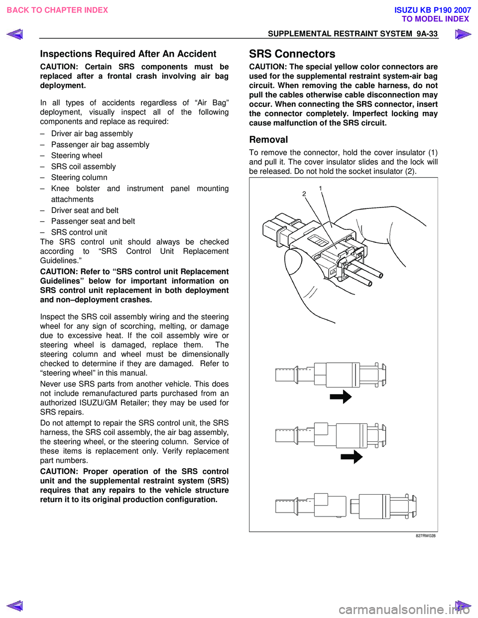
SRS Connectors
CAUTION: The special yellow color connectors are
used for the supplemental restraint system-air bag
circuit. When removing the cable harness, do not
pull the cables otherwise cable disconnection may
occur. When connecting the SRS connector, insert
the connector completely. Imperfect locking may
cause malfunction of the SRS circuit.
Removal
To remove the connector, hold the cover insulator (1)
and pull it. The cover insulator slides and the lock will
be released. Do not hold the socket insulator (2).
827RW 028
BACK TO CHAPTER INDEX TO MODEL INDEXISUZU KB P190 2007