2007 ISUZU KB P190 tire size
[x] Cancel search: tire sizePage 2008 of 6020
6-8 ENGINE DIAGNOSIS (C24SE)
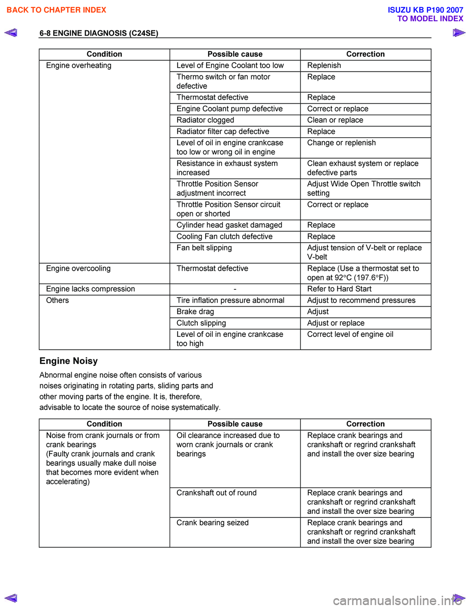
Condition Possible cause Correction
Engine overheating Level of Engine Coolant too low Replenish
Thermo switch or fan motor
defective Replace
Thermostat
defective Replace
Engine Coolant pump defective Correct or replace
Radiator clogged Clean or replace
Radiator filter cap defective Replace
Level of oil in engine crankcase
too low or wrong oil in engine Change or replenish
Resistance in exhaust system
increased Clean exhaust system or replace
defective parts
Throttle Position Sensor
adjustment incorrect Adjust Wide Open Throttle switch
setting
Throttle Position Sensor circuit
open or shorted Correct or replace
Cylinder head gasket damaged Replace
Cooling Fan clutch defective Replace
Fan belt slipping Adjust tension of V-belt or replace
V-belt
Engine overcooling Thermostat defective Replace (Use a thermostat set to
open at 92 °C (197.6 °F))
Engine lacks compression - Refer to Hard Start
Others Tire inflation pressure abnormal Adjust to recommend pressures
Brake drag Adjust
Clutch slipping Adjust or replace
Level of oil in engine crankcase
too high Correct level of engine oil
Engine Noisy
Abnormal engine noise often consists of various
noises originating in rotating parts, sliding parts and
other moving parts of the engine. It is, therefore,
advisable to locate the source of noise systematically.
Condition Possible cause Correction
Noise from crank journals or from
crank bearings
(Faulty crank journals and crank
bearings usually make dull noise
that becomes more evident when
accelerating) Oil clearance increased due to
worn crank journals or crank
bearings Replace crank bearings and
crankshaft or regrind crankshaft
and install the over size bearing
Crankshaft out of round Replace crank bearings and
crankshaft or regrind crankshaft
and install the over size bearing
Crank bearing seized Replace crank bearings and
crankshaft or regrind crankshaft
and install the over size bearing
BACK TO CHAPTER INDEX
TO MODEL INDEX
ISUZU KB P190 2007
Page 2519 of 6020
Engine Mechanical – V6 Page 6A1–40
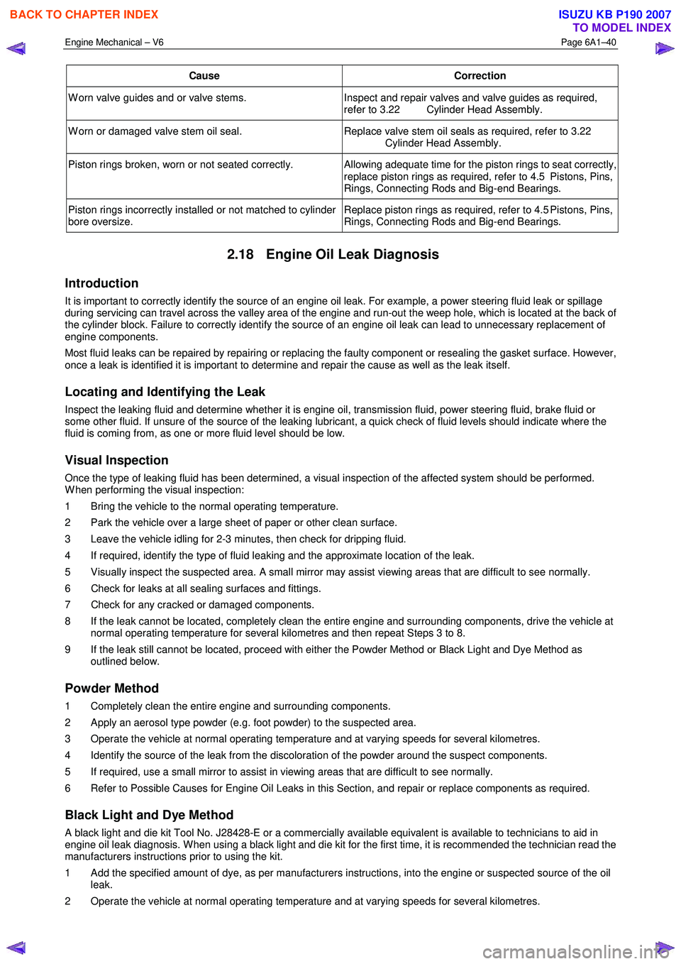
Cause Correction
W orn valve guides and or valve stems. Inspect and repair valves and valve guides as required,
refer to 3.22 Cylinder Head Assembly.
W orn or damaged valve stem oil seal. Replace valve stem oil seals as required, refer to 3.22
Cylinder Head Assembly.
Piston rings broken, worn or not seated correctly. Allowing adequate time for the piston rings to seat correctly,
replace piston rings as required, refer to 4.5 Pistons, Pins,
Rings, Connecting Rods and Big-end Bearings.
Piston rings incorrectly installed or not matched to cylinder
bore oversize. Replace piston rings as required, refer to 4.5 Pistons, Pins,
Rings, Connecting Rods and Big-end Bearings.
2.18 Engine Oil Leak Diagnosis
Introduction
It is important to correctly identify the source of an engine oil leak. For example, a power steering fluid leak or spillage
during servicing can travel across the valley area of the engine and run-out the weep hole, which is located at the back of
the cylinder block. Failure to correctly identify the source of an engine oil leak can lead to unnecessary replacement of
engine components.
Most fluid leaks can be repaired by repairing or replacing the faulty component or resealing the gasket surface. However,
once a leak is identified it is important to determine and repair the cause as well as the leak itself.
Locating and Identifying the Leak
Inspect the leaking fluid and determine whether it is engine oil, transmission fluid, power steering fluid, brake fluid or
some other fluid. If unsure of the source of the leaking lubricant, a quick check of fluid levels should indicate where the
fluid is coming from, as one or more fluid level should be low.
Visual Inspection
Once the type of leaking fluid has been determined, a visual inspection of the affected system should be performed.
W hen performing the visual inspection:
1 Bring the vehicle to the normal operating temperature.
2 Park the vehicle over a large sheet of paper or other clean surface.
3 Leave the vehicle idling for 2-3 minutes, then check for dripping fluid.
4 If required, identify the type of fluid leaking and the approximate location of the leak.
5 Visually inspect the suspected area. A small mirror may assist viewing areas that are difficult to see normally.
6 Check for leaks at all sealing surfaces and fittings.
7 Check for any cracked or damaged components.
8 If the leak cannot be located, completely clean the entire engine and surrounding components, drive the vehicle at normal operating temperature for several kilometres and then repeat Steps 3 to 8.
9 If the leak still cannot be located, proceed with either the Powder Method or Black Light and Dye Method as outlined below.
Powder Method
1 Completely clean the entire engine and surrounding components.
2 Apply an aerosol type powder (e.g. foot powder) to the suspected area.
3 Operate the vehicle at normal operating temperature and at varying speeds for several kilometres.
4 Identify the source of the leak from the discoloration of the powder around the suspect components.
5 If required, use a small mirror to assist in viewing areas that are difficult to see normally.
6 Refer to Possible Causes for Engine Oil Leaks in this Section, and repair or replace components as required.
Black Light and Dye Method
A black light and die kit Tool No. J28428-E or a commercially available equivalent is available to technicians to aid in
engine oil leak diagnosis. W hen using a black light and die kit for the first time, it is recommended the technician read the
manufacturers instructions prior to using the kit.
1 Add the specified amount of dye, as per manufacturers instructions, into the engine or suspected source of the oil leak.
2 Operate the vehicle at normal operating temperature and at varying speeds for several kilometres.
BACK TO CHAPTER INDEX
TO MODEL INDEX
ISUZU KB P190 2007
Page 2693 of 6020
Engine Mechanical – V6 Page 6A1–214
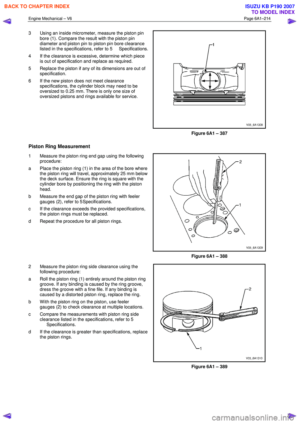
3 Using an inside micrometer, measure the piston pin
bore (1). Compare the result with the piston pin
diameter and piston pin to piston pin bore clearance
listed in the specifications, refer to 5 Specifications.
4 If the clearance is excessive, determine which piece is out of specification and replace as required.
5 Replace the piston if any of its dimensions are out of specification.
6 If the new piston does not meet clearance specifications, the cylinder block may need to be
oversized to 0.25 mm. There is only one size of
oversized pistons and rings available for service.
Figure 6A1 – 387
Piston Ring Measurement
1 Measure the piston ring end gap using the following procedure:
a Place the piston ring (1) in the area of the bore where the piston ring will travel, approximately 25 mm below
the deck surface. Ensure the ring is square with the
cylinder bore by positioning the ring with the piston
head.
b Measure the end gap of the piston ring with feeler gauges (2), refer to 5 Specifications.
c If the clearance exceeds the provided specifications, the piston rings must be replaced.
d Repeat the procedure for all piston rings.
Figure 6A1 – 388
2 Measure the piston ring side clearance using the following procedure:
a Roll the piston ring (1) entirely around the piston ring groove. If any binding is caused by the ring groove,
dress the groove with a fine file. If any binding is
caused by a distorted piston ring, replace the ring.
b W ith the piston ring on the piston, use feeler gauges (2) to check clearance at multiple locations.
c Compare the measurements with piston ring side clearance listed in the specifications, refer to 5
Specifications.
d If the clearance is greater than specifications, replace the piston rings.
Figure 6A1 – 389
BACK TO CHAPTER INDEX
TO MODEL INDEX
ISUZU KB P190 2007
Page 4411 of 6020
TRANSMISSION CONTROL SYSTEM (JR405E) 7A2-127
RTW77AXF001001
0
10
20
30
40
50
60
70
80
90
100
0
10
20
30
40
50
60
70
80
90
100
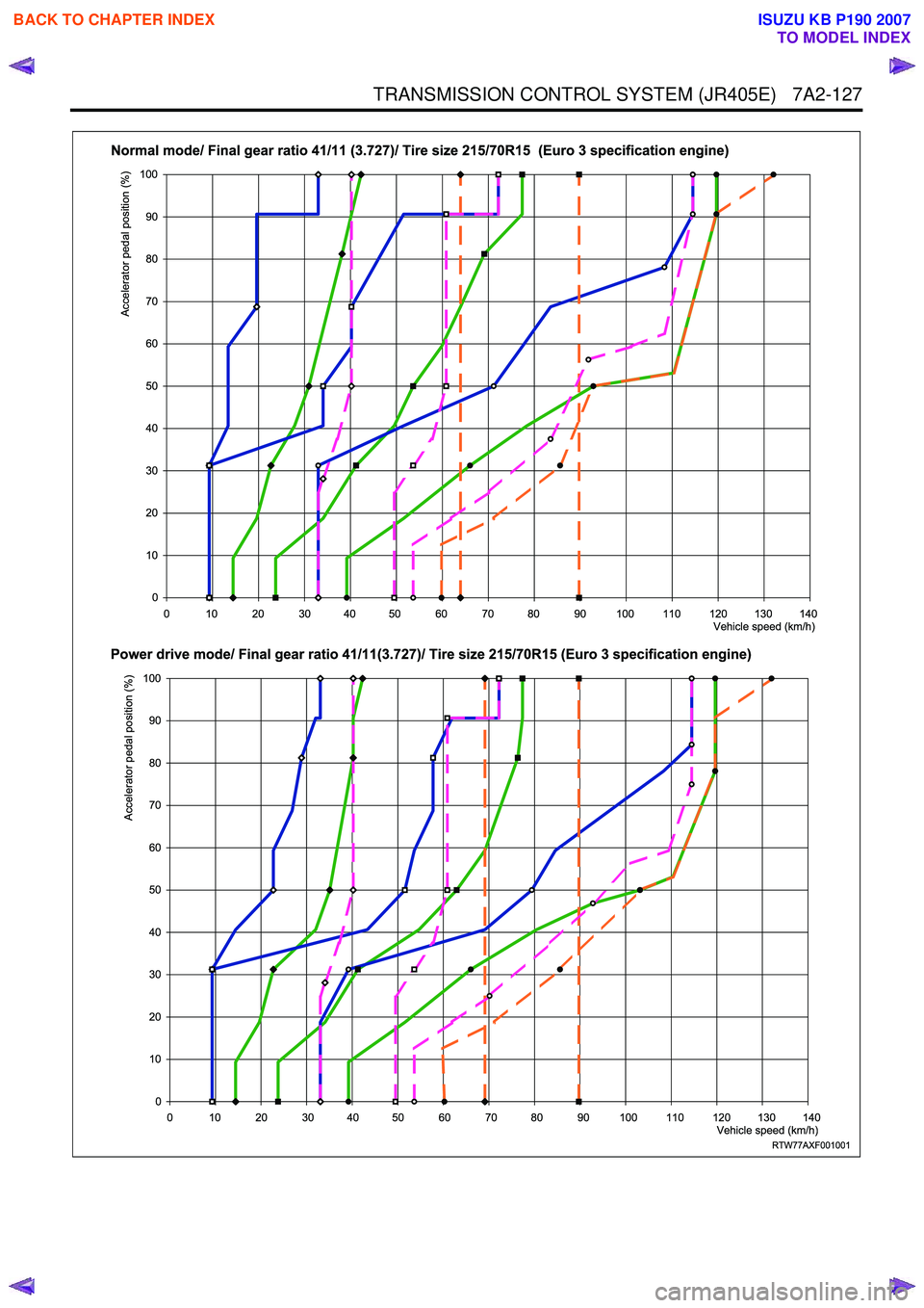
Normal mode/ Final gear ratio 41/11 (3.727)/ Tire size 215/70R15 (Euro 3 specification engine)
Power drive mode/ Final gear ratio 41/11(3.727)/ Tire size 215/70R15 (Euro 3 specification engine)
Accelerator pedal position (%)
Vehicle speed (km/h)
0 10 20 30 40 50 60 70 80 90 100 110 120 130 140
Accelerator pedal position (%)
Vehicle speed (km/h)
0 10 20 30 40 50 60 70 80 90 100 110 120 130 140
BACK TO CHAPTER INDEX
TO MODEL INDEX
ISUZU KB P190 2007
Page 4412 of 6020
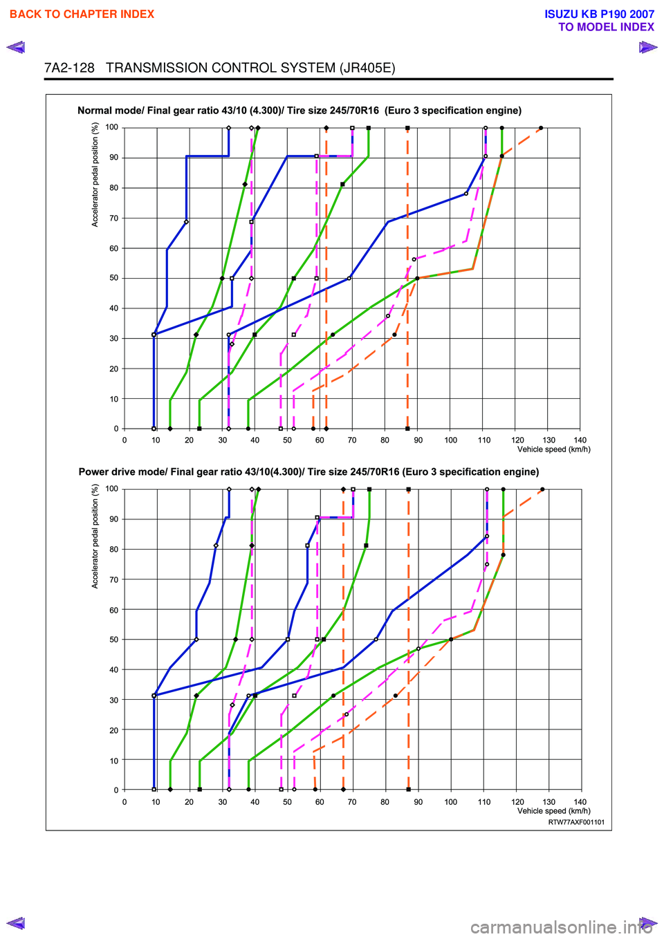
7A2-128 TRANSMISSION CONTROL SYSTEM (JR405E)
RTW77AXF001101
0
10
20
30
40
50
60
70
80
90
100
Accelerator pedal position (%)
Vehicle speed (km/h)
0 10 20 30 40 50 60 70 80 90 100 110 120 130 140
0
10
20
30
40
50
60
70
80
90
100
Accelerator pedal position (%)
Vehicle speed (km/h)
0 10 20 30 40 50 60 70 80 90 100 110 120 130 140
Normal mode/ Final gear ratio 43/10 (4.300)/ Tire size 245/70R16 (Euro 3 specification engine)
Power drive mode/ Final gear ratio 43/10(4.300)/ Tire size 245/70R16 (Euro 3 specification engine)
BACK TO CHAPTER INDEX
TO MODEL INDEX
ISUZU KB P190 2007
Page 4413 of 6020
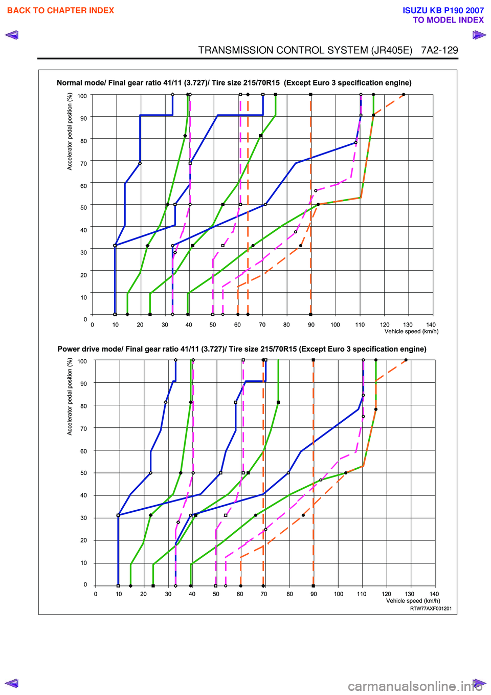
TRANSMISSION CONTROL SYSTEM (JR405E) 7A2-129
RTW77AXF001201
0
10
20
30
40
50
60
70
80
90
100
Accelerator pedal position (%)
Vehicle speed (km/h)
0 10 20 30 40 50 60 70 80 90 100 110 120 130 140
0
10
20
30
40
50
60
70
80
90
100
Accelerator pedal position (%)
Vehicle speed (km/h)
0 10 20 30 40 50 60 70 80 90 100 110 120 130 140
Normal mode/ Final gear ratio 41/11 (3.727)/ Tire size 215/70R15 (Except Euro 3 specification engine)
Power drive mode/ Final gear ratio 41/11 (3.727)/ Tire size 215/70R15 (Except Euro 3 specification engine)
BACK TO CHAPTER INDEX
TO MODEL INDEX
ISUZU KB P190 2007
Page 4414 of 6020
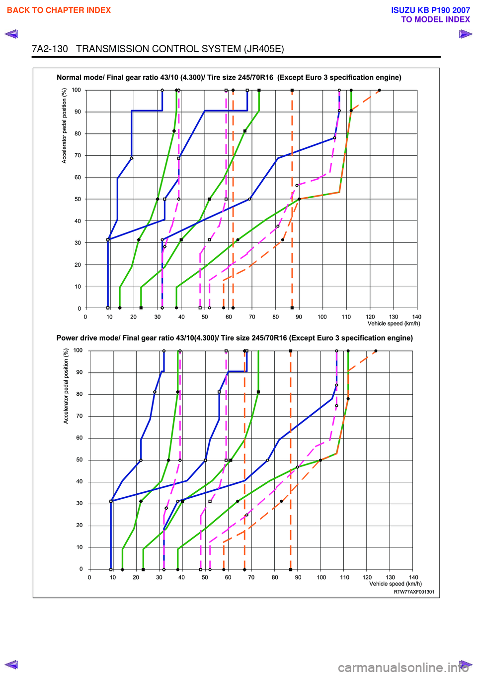
7A2-130 TRANSMISSION CONTROL SYSTEM (JR405E)
RTW77AXF001301
0
10
20
30
40
50
60
70
80
90
100
0
10
20
30
40
50
60
70
80
90
100
Normal mode/ Final gear ratio 43/10 (4.300)/ Tire size 245/70R16 (Except Euro 3 specification engine)
Power drive mode/ Final gear ratio 43/10(4.300)/ Tire size 245/70R16 (Except Euro 3 specification engine)
Accelerator pedal position (%)
Vehicle speed (km/h)
0 10 20 30 40 50 60 70 80 90 100 110 120 130 140
Accelerator pedal position (%)
Vehicle speed (km/h)
0 10 20 30 40 50 60 70 80 90 100 110 120 130 140
BACK TO CHAPTER INDEX
TO MODEL INDEX
ISUZU KB P190 2007
Page 4415 of 6020
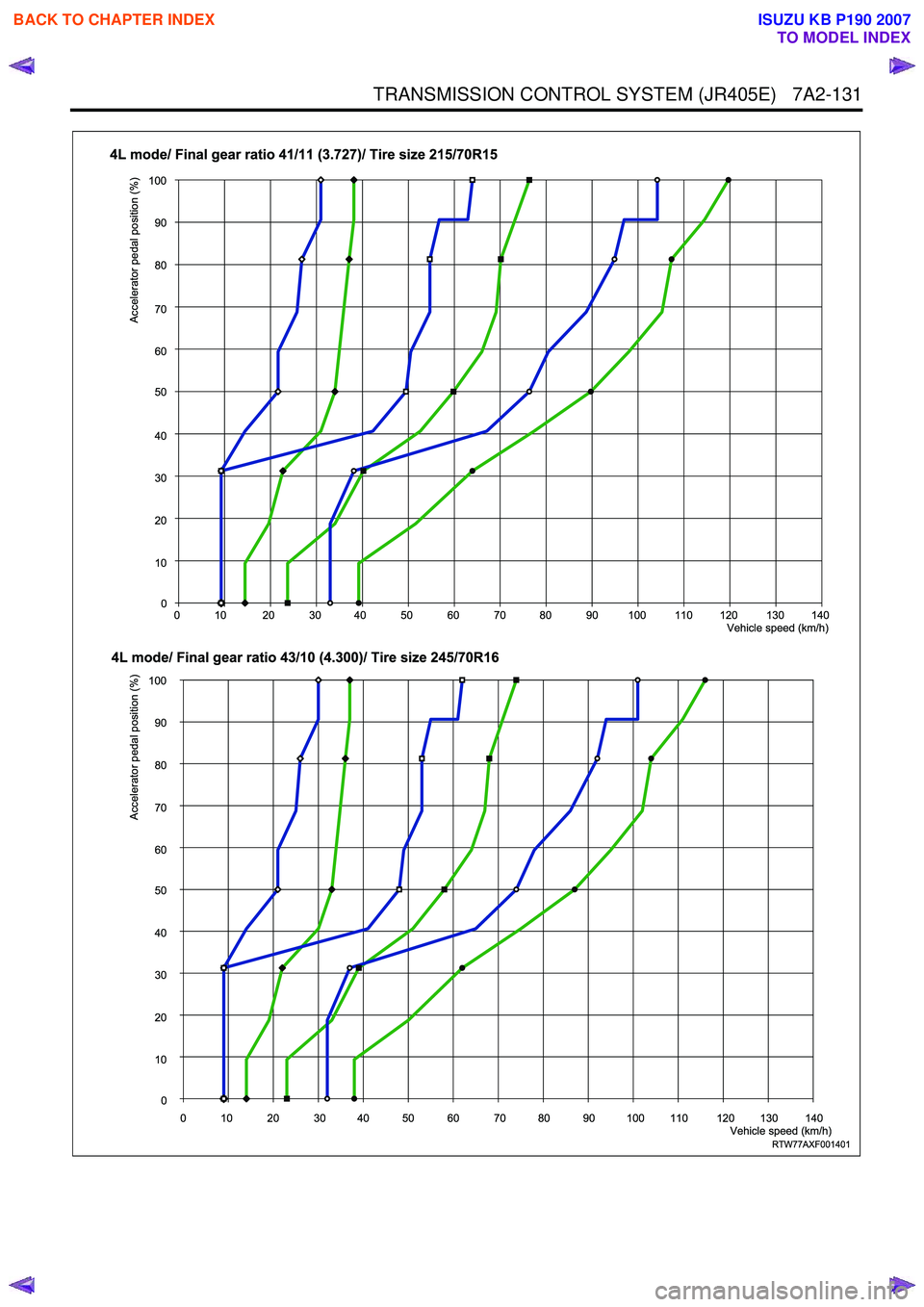
TRANSMISSION CONTROL SYSTEM (JR405E) 7A2-131
RTW77AXF001401
0
10
20
30
40
50
60
70
80
90
100
Accelerator pedal position (%)
Vehicle speed (km/h)
0 10 20 30 40 50 60 70 80 90 100 110 120 130 140
0
10
20
30
40
50
60
70
80
90
100
Accelerator pedal position (%)
Vehicle speed (km/h)
0 10 20 30 40 50 60 70 80 90 100 110 120 130 140
4L mode/ Final gear ratio 41/11 (3.727)/ Tire size 215/70R15
4L mode/ Final gear ratio 43/10 (4.300)/ Tire size 245/70R16
BACK TO CHAPTER INDEX
TO MODEL INDEX
ISUZU KB P190 2007