2007 ISUZU KB P190 fuses
[x] Cancel search: fusesPage 1617 of 6020
ENGINE ELECTRICAL (4JK1/4JJ1) 6D-29
Pre-Heating System
Inspection and Repair
Make the necessary adjustments, repairs, and part
replacement if excessive wear of damage is discovered
during inspection.
Visual Check
Check the main fuses and glow indicator for damage.
Replace the part(s) if required.
Glow Relay
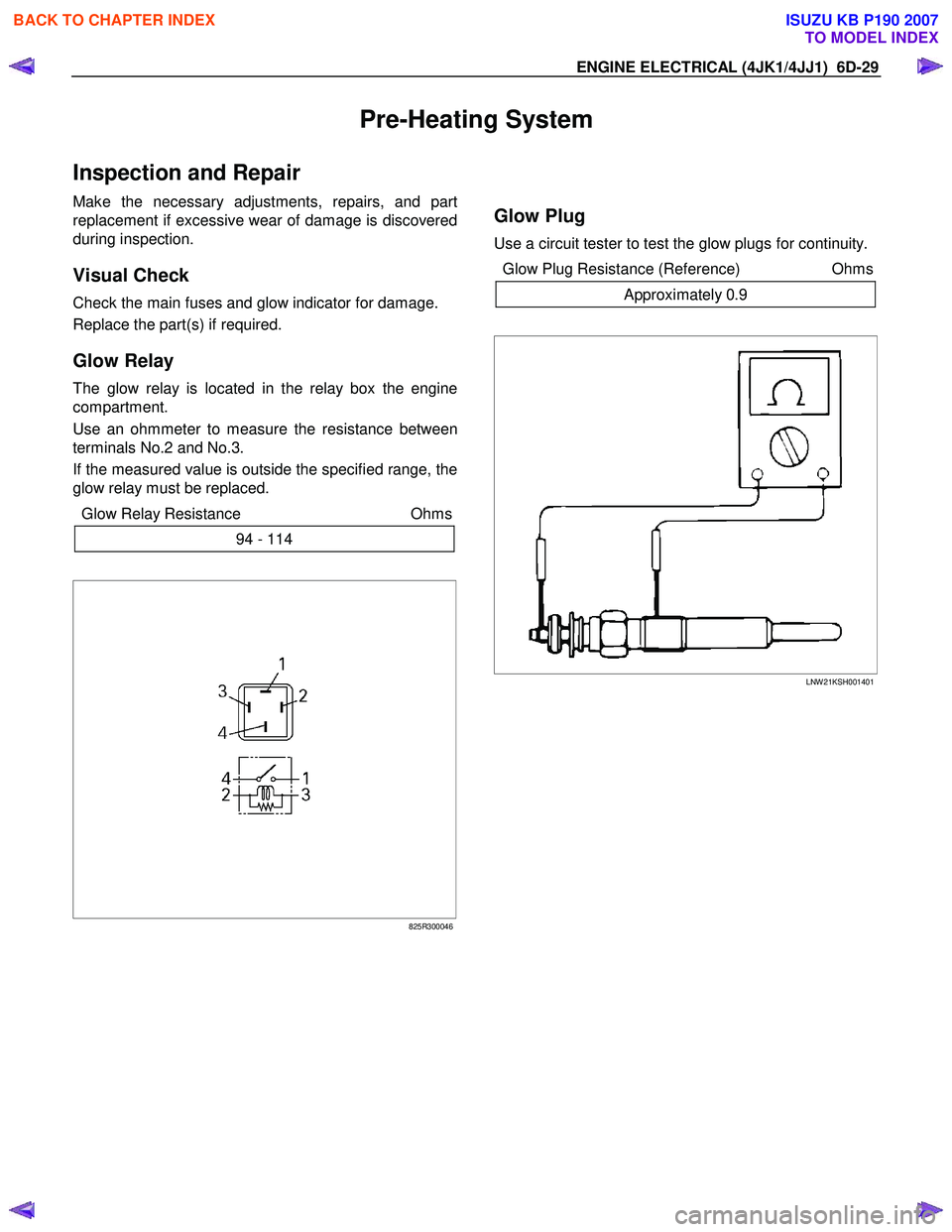
The glow relay is located in the relay box the engine
compartment.
Use an ohmmeter to measure the resistance between
terminals No.2 and No.3.
If the measured value is outside the specified range, the
glow relay must be replaced.
Glow Relay Resistance Ohms
94 - 114
825R300046
Glow Plug
Use a circuit tester to test the glow plugs for continuity.
Glow Plug Resistance (Reference) Ohms
Approximately 0.9
LNW 21KSH001401
BACK TO CHAPTER INDEX
TO MODEL INDEX
ISUZU KB P190 2007
Page 1942 of 6020
ENGINE CONTROL SYSTEM (4JK1/4JJ1) 6E-325
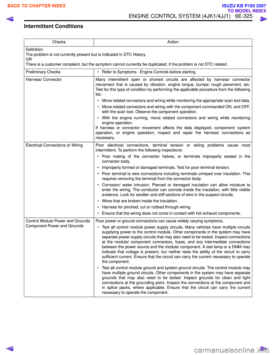
Intermittent Conditions
ChecksAction
Definition:
The problem is not currently present but is indicated in DTC History.
OR
There is a customer complaint, but the symptom cannot currently be duplicated, if the problem is not DTC related.
Preliminary Checks • Refer to Symptoms - Engine Controls before starting.
Harness/ Connector Many intermittent open or shorted circuits are affected by harness/ connector
movement that is caused by vibration, engine torque, bumps/ rough pavement, etc.
Test for this type of condition by performing the applicable procedure from the following
list:
• Move related connectors and wiring while monitoring the appropriate scan tool data.
• Move related connectors and wiring with the component commanded ON, and OFF, with the scan tool. Observe the component operation.
• With the engine running, move related connectors and wiring while monitoring engine operation.
If harness or connector movement affects the data displayed, component/ system
operation, or engine operation, inspect and repair the harness/ connections as
necessary.
Electrical Connections or Wiring Poor electrical connections, terminal tension or wiring problems cause most intermittent. To perform the following inspections:
• Poor mating of the connector halves, or terminals improperly seated in the connector body.
• Improperly formed or damaged terminals. Test for poor terminal tension.
• Poor terminal to wire connections including terminals crimped over insulation. This requires removing the terminal from the connector body.
• Corrosion/ water intrusion. Pierced or damaged insulation can allow moisture to enter the wiring. The conductor can corrode inside the insulation, with little visible
evidence. Look for swollen and stiff sections of wire in the suspect circuits.
• Wires that are broken inside the insulation.
• Harness for pinched, cut or rubbed through wiring.
• Ensure that the wiring does not come in contact with hot exhaust components.
Control Module Power and Grounds
Component Power and Grounds Poor power or ground connections can cause widely varying symptoms.
• Test all control module power supply circuits. Many vehicles have multiple circuits supplying power to the control module. Other components in the system may have
separate power supply circuits that may also need to be tested. Inspect connections
at the module/ component connectors, fuses, and any intermediate connections
between the power source and the module/ component. A test lamp or a DMM may
indicate that voltage is present, but neither tests the ability of the circuit to carry
sufficient current. Ensure that the circuit can carry the current necessary to operate
the component.
• Test all control module ground and system ground circuits. The control module may have multiple ground circuits. Other components in the system may have separate
grounds that may also need to be tested. Inspect grounds for clean and tight
connections at the grounding point. Inspect the connections at the component and
in splice packs, where applicable. Ensure that the circuit can carry the current
necessary to operate the component.
BACK TO CHAPTER INDEX
TO MODEL INDEX
ISUZU KB P190 2007
Page 2232 of 6020
6E–62 ENGINE DRIVEABILITY AND EMISSIONS
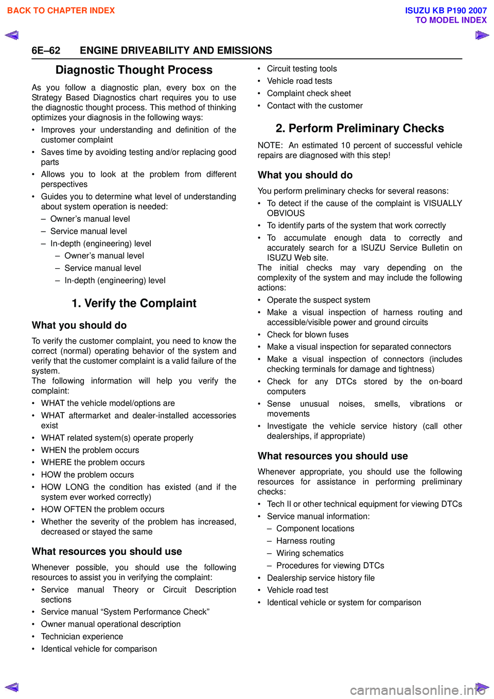
Diagnostic Thought Process
As you follow a diagnostic plan, every box on the
Strategy Based Diagnostics chart requires you to use
the diagnostic thought process. This method of thinking
optimizes your diagnosis in the following ways:
• Improves your understanding and definition of the customer complaint
• Saves time by avoiding testing and/or replacing good parts
• Allows you to look at the problem from different perspectives
• Guides you to determine what level of understanding about system operation is needed:
– Owner’s manual level
– Service manual level
– In-depth (engineering) level – Owner’s manual level
– Service manual level
– In-depth (engineering) level
1. Verify the Complaint
What you should do
To verify the customer complaint, you need to know the
correct (normal) operating behavior of the system and
verify that the customer complaint is a valid failure of the
system.
The following information will help you verify the
complaint:
• WHAT the vehicle model/options are
• WHAT aftermarket and dealer-installed accessories exist
• WHAT related system(s) operate properly
• WHEN the problem occurs
• WHERE the problem occurs
• HOW the problem occurs
• HOW LONG the condition has existed (and if the system ever worked correctly)
• HOW OFTEN the problem occurs
• Whether the severity of the problem has increased, decreased or stayed the same
What resources you should use
Whenever possible, you should use the following
resources to assist you in verifying the complaint:
• Service manual Theory or Circuit Description sections
• Service manual “System Performance Check”
• Owner manual operational description
• Technician experience
• Identical vehicle for comparison • Circuit testing tools
• Vehicle road tests
• Complaint check sheet
• Contact with the customer
2. Perform Preliminary Checks
NOTE: An estimated 10 percent of successful vehicle
repairs are diagnosed with this step!
What you should do
You perform preliminary checks for several reasons:
• To detect if the cause of the complaint is VISUALLY OBVIOUS
• To identify parts of the system that work correctly
• To accumulate enough data to correctly and accurately search for a ISUZU Service Bulletin on
ISUZU Web site.
The initial checks may vary depending on the
complexity of the system and may include the following
actions:
• Operate the suspect system
• Make a visual inspection of harness routing and accessible/visible power and ground circuits
• Check for blown fuses
• Make a visual inspection for separated connectors
• Make a visual inspection of connectors (includes checking terminals for damage and tightness)
• Check for any DTCs stored by the on-board computers
• Sense unusual noises, smells, vibrations or movements
• Investigate the vehicle service history (call other dealerships, if appropriate)
What resources you should use
Whenever appropriate, you should use the following
resources for assistance in performing preliminary
checks:
• Tech II or other technical equipment for viewing DTCs
• Service manual information: – Component locations
– Harness routing
– Wiring schematics
– Procedures for viewing DTCs
• Dealership service history file
• Vehicle road test
• Identical vehicle or system for comparison
BACK TO CHAPTER INDEX
TO MODEL INDEX
ISUZU KB P190 2007
Page 2403 of 6020
ENGINE DRIVEABILITY AND EMISSIONS 6E–233
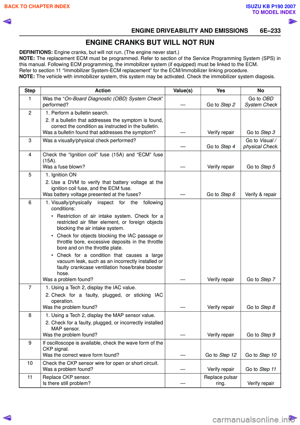
ENGINE CRANKS BUT WILL NOT RUN
DEFINITIONS: Engine cranks, but will not run. (The engine never start.)
NOTE: The replacement ECM must be programmed. Refer to section of the Service Programming System (SPS) in
this manual. Following ECM programming, the immobilizer system (if equipped) must be linked to the ECM.
Refer to section 11 “Immobilizer System-ECM replacement” for the ECM/Immobilizer linking procedure.
NOTE: The vehicle with immobilizer system, this system may be activated. Check the immobilizer system diagosis.
Step Action Value(s) Yes No
1 Was the “ On-Board Diagnostic (OBD) System Check ”
performed? — Go to Step 2Go to
OBD
System Check
2 1. Perform a bulletin search. 2. If a bulletin that addresses the symptom is found,correct the condition as instructed in the bulletin.
Was a bulletin found that addresses the symptom? — Verify repair Go to Step 3
3 Was a visually/physical check performed? —Go to Step 4Go to
Visual /
physical Check.
4 Check the “Ignition coil” fuse (15A) and “ECM” fuse (15A).
Was a fuse blown? — Verify repair Go to Step 5
5 1. Ignition ON 2. Use a DVM to verify that battery voltage at theignition coil fuse, and the ECM fuse.
Was battery voltage presented at the fuses? — Go to Step 6Verify & repair
6 1. Visually/physically inspect for the following conditions:
• Restriction of air intake system. Check for a restricted air filter element, or foreign objects
blocking the air intake system.
• Check for objects blocking the IAC passage or throttle bore, excessive deposits in the throttle
bore and on the throttle plate.
• Check for a condition that causes a large vacuum leak, such as an incorrectly installed or
faulty crankcase ventilation hose/brake booster
hose.
Was a problem found? — Verify repair Go to Step 7
7 1. Using a Tech 2, display the IAC value. 2. Check for a faulty, plugged, or sticking IACoperation.
Was the problem found? — Verify repair Go to Step 8
8 1. Using a Tech 2, display the MAP sensor value. 2. Check for a faulty, plugged, or incorrectly installedMAP sensor.
Was the problem found? — Verify repair Go to Step 9
9 If oscilloscope is available, check the wave form of the CKP signal.
Was the correct wave form found? — Go to Step 12Go to Step 10
10 Check the CKP sensor wire for open or short circuit. Was a problem found? — Verify repair Go to Step 11
11 Replace CKP sensor. Is there still problem? —Replace pulsar
ring. Verify repair
BACK TO CHAPTER INDEX
TO MODEL INDEX
ISUZU KB P190 2007
Page 2517 of 6020
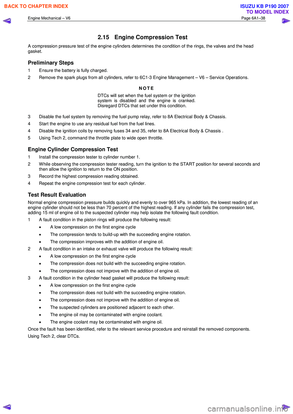
Engine Mechanical – V6 Page 6A1–38
2.15 Engine Compression Test
A compression pressure test of the engine cylinders determines the condition of the rings, the valves and the head
gasket.
Preliminary Steps
1 Ensure the battery is fully charged.
2 Remove the spark plugs from all cylinders, refer to 6C1-3 Engine Management – V6 – Service Operations.
NOTE
DTCs will set when the fuel system or the ignition
system is disabled and the engine is cranked.
Disregard DTCs that set under this condition.
3 Disable the fuel system by removing the fuel pump relay, refer to 8A Electrical Body & Chassis.
4 Start the engine to use any residual fuel from the fuel lines.
4 Disable the ignition coils by removing fuses 34 and 35, refer to 8A Electrical Body & Chassis .
5 Using Tech 2, command the throttle plate to wide open throttle.
Engine Cylinder Compression Test
1 Install the compression tester to cylinder number 1.
2 W hile observing the compression tester reading, turn the ignition to the START position for several seconds and then allow the ignition to return to the ON position.
3 Record the highest compression reading obtained.
4 Repeat the engine compression test for each cylinder.
Test Result Evaluation
Normal engine compression pressure builds quickly and evenly to over 965 kPa. In addition, the lowest reading of an
engine cylinder should not be less than 70 percent of the highest reading. If any cylinder fails the compression test,
adding 15 ml of engine oil to the suspected cylinder may help isolate the following fault condition.
1 A fault condition in the piston rings will produce the following result:
• A low compression on the first engine cycle
• The compression tends to build-up with the succeeding engine rotation.
• The compression improves with the addition of engine oil.
2 A fault condition in an intake or exhaust valve will produce the following result:
• A low compression on the first engine cycle
• The compression does not build with the succeeding engine rotation.
• The compression does not improve with the addition of engine oil.
3 A fault condition in the cylinder head gasket will produce the following result:
• A low compression on the first engine cycle
• The compression does not build with the succeeding engine rotation.
• The compression does not improve with the addition of engine oil.
• The suspected cylinders are positioned adjacent to each other.
• The engine oil may be contaminated with engine coolant.
• The engine coolant may be contaminated with engine oil.
Once the fault has been identified, refer to the relevant service procedure and reinstall the removed components.
Using Tech 2, clear DTCs.
BACK TO CHAPTER INDEX
TO MODEL INDEX
ISUZU KB P190 2007
Page 2822 of 6020
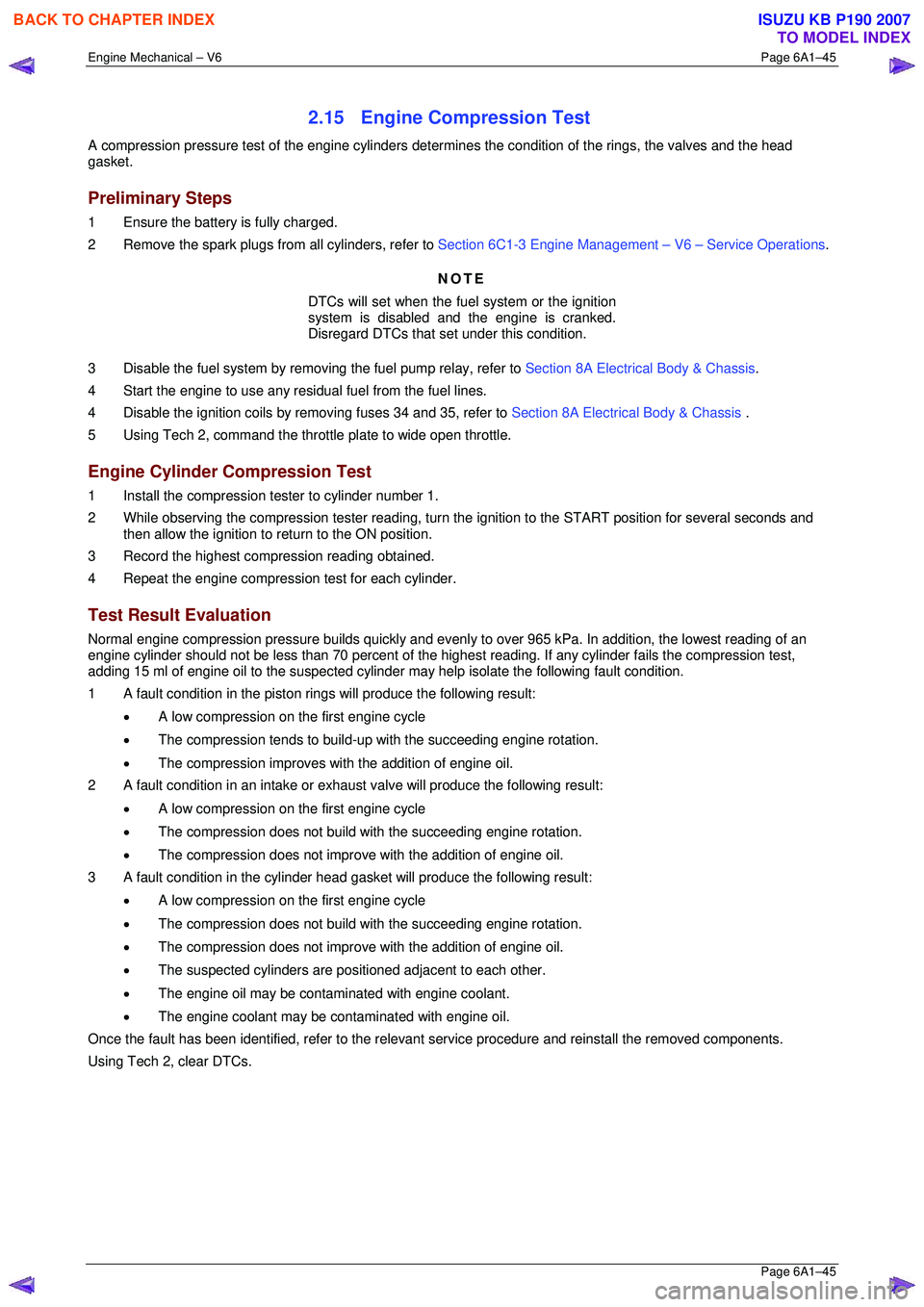
Engine Mechanical – V6 Page 6A1–45
Page 6A1–45
2.15 Engine Compression Test
A compression pressure test of the engine cylinders determines the condition of the rings, the valves and the head
gasket.
Preliminary Steps
1 Ensure the battery is fully charged.
2 Remove the spark plugs from all cylinders, refer to Section 6C1-3 Engine Management – V6 – Service Operations.
NOTE
DTCs will set when the fuel system or the ignition
system is disabled and the engine is cranked.
Disregard DTCs that set under this condition.
3 Disable the fuel system by removi ng the fuel pump relay, refer to Section 8A Electrical Body & Chassis .
4 Start the engine to use any resi dual fuel from the fuel lines.
4 Disable the ignition coils by removing fuses 34 and 35, refer to Section 8A Electrical Body & Chassis .
5 Using Tech 2, command the throttle plate to wide open throttle.
Engine Cylinder Compression Test
1 Install the compression tester to cylinder number 1.
2 While observing the compression tester reading, turn t he ignition to the START position for several seconds and
then allow the ignition to return to the ON position.
3 Record the highest compression reading obtained.
4 Repeat the engine compression test for each cylinder.
Test Result Evaluation
Normal engine compression pressure builds quickly and evenly to over 965 kPa. In addition, the lowest reading of an
engine cylinder should not be less than 70 per cent of the highest reading. If any cylinder fails the compression test,
adding 15 ml of engine oil to the suspected cylinder may help isolate the following fault condition.
1 A fault condition in the piston rings will produce the following result:
• A low compression on the first engine cycle
• The compression tends to build-up with the succeeding engine rotation.
• The compression improves with the addition of engine oil.
2 A fault condition in an intake or exhaus t valve will produce the following result:
• A low compression on the first engine cycle
• The compression does not build with the succeeding engine rotation.
• The compression does not improve with the addition of engine oil.
3 A fault condition in the cylinder head gasket will produce the following result:
• A low compression on the first engine cycle
• The compression does not build with the succeeding engine rotation.
• The compression does not improve with the addition of engine oil.
• The suspected cylinders are pos itioned adjacent to each other.
• The engine oil may be contaminated with engine coolant.
• The engine coolant may be cont aminated with engine oil.
Once the fault has been identified, refe r to the relevant service procedure and reinstall the removed components.
Using Tech 2, clear DTCs.
BACK TO CHAPTER INDEX
TO MODEL INDEX
ISUZU KB P190 2007
Page 3245 of 6020
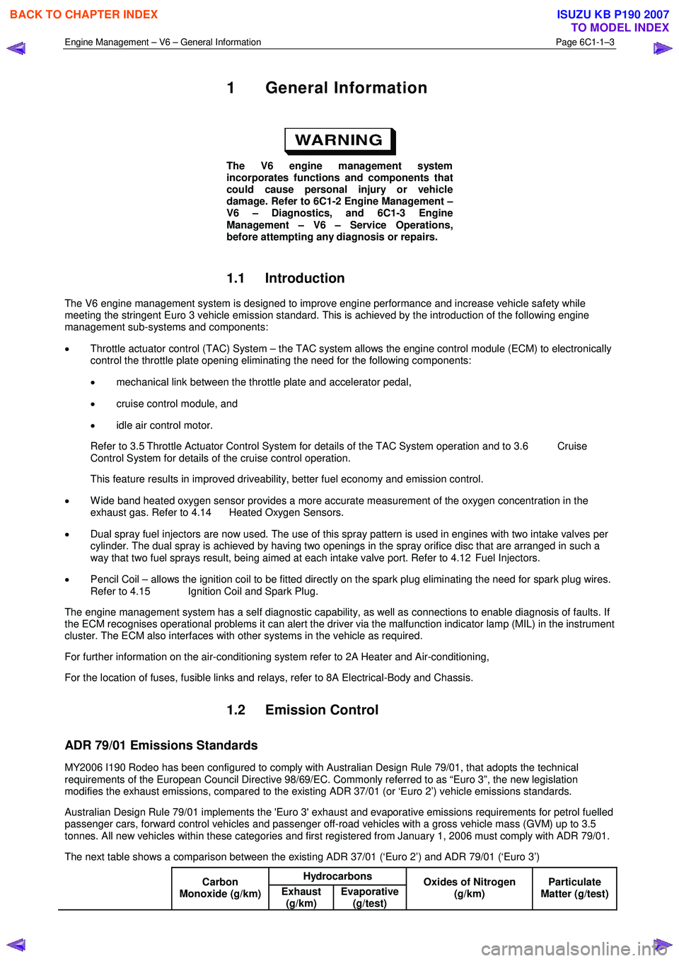
Engine Management – V6 – General Information Page 6C1-1–3
1 General Information
The V6 engine management system
incorporates functions and components that
could cause personal injury or vehicle
damage. Refer to 6C1-2 Engine Management –
V6 – Diagnostics, and 6C1-3 Engine
Management – V6 – Service Operations,
before attempting any diagnosis or repairs.
1.1 Introduction
The V6 engine management system is designed to improve engine performance and increase vehicle safety while
meeting the stringent Euro 3 vehicle emission standard. This is achieved by the introduction of the following engine
management sub-systems and components:
• Throttle actuator control (TAC) System – the TAC system allows the engine control module (ECM) to electronically
control the throttle plate opening eliminating the need for the following components:
• mechanical link between the throttle plate and accelerator pedal,
• cruise control module, and
• idle air control motor.
Refer to 3.5 Throttle Actuator Control System for details of the TAC System operation and to 3.6 Cruise Control System for details of the cruise control operation.
This feature results in improved driveability, better fuel economy and emission control.
• W ide band heated oxygen sensor provides a more accurate measurement of the oxygen concentration in the
exhaust gas. Refer to 4.14 Heated Oxygen Sensors.
• Dual spray fuel injectors are now used. The use of this spray pattern is used in engines with two intake valves per
cylinder. The dual spray is achieved by having two openings in the spray orifice disc that are arranged in such a
way that two fuel sprays result, being aimed at each intake valve port. Refer to 4.12 Fuel Injectors.
• Pencil Coil – allows the ignition coil to be fitted directly on the spark plug eliminating the need for spark plug wires.
Refer to 4.15 Ignition Coil and Spark Plug.
The engine management system has a self diagnostic capability, as well as connections to enable diagnosis of faults. If
the ECM recognises operational problems it can alert the driver via the malfunction indicator lamp (MIL) in the instrument
cluster. The ECM also interfaces with other systems in the vehicle as required.
For further information on the air-conditioning system refer to 2A Heater and Air-conditioning,
For the location of fuses, fusible links and relays, refer to 8A Electrical-Body and Chassis.
1.2 Emission Control
ADR 79/01 Emissions Standards
MY2006 I190 Rodeo has been configured to comply with Australian Design Rule 79/01, that adopts the technical
requirements of the European Council Directive 98/69/EC. Commonly referred to as “Euro 3”, the new legislation
modifies the exhaust emissions, compared to the existing ADR 37/01 (or ‘Euro 2’) vehicle emissions standards.
Australian Design Rule 79/01 implements the 'Euro 3' exhaust and evaporative emissions requirements for petrol fuelled
passenger cars, forward control vehicles and passenger off-road vehicles with a gross vehicle mass (GVM) up to 3.5
tonnes. All new vehicles within these categories and first registered from January 1, 2006 must comply with ADR 79/01.
The next table shows a comparison between the existing ADR 37/01 (‘Euro 2’) and ADR 79/01 (‘Euro 3’) Hydrocarbons
Carbon
Monoxide (g/km) Exhaust
(g/km) Evaporative
(g/test) Oxides of Nitrogen
(g/km) Particulate
Matter (g/test)
BACK TO CHAPTER INDEX
TO MODEL INDEX
ISUZU KB P190 2007
Page 3297 of 6020
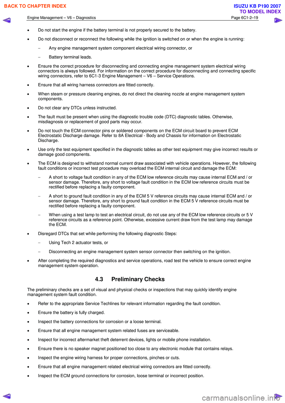
Engine Management – V6 – Diagnostics Page 6C1-2–19
• Do not start the engine if the battery terminal is not properly secured to the battery.
• Do not disconnect or reconnect the following while the ignition is switched on or when the engine is running:
− Any engine management system component electrical wiring connector, or
− Battery terminal leads.
• Ensure the correct procedure for disconnecting and connecting engine management system electrical wiring
connectors is always followed. For information on the correct procedure for disconnecting and connecting specific
wiring connectors, refer to 6C1-3 Engine Management – V6 – Service Operations.
• Ensure that all wiring harness connectors are fitted correctly.
• W hen steam or pressure cleaning engines, do not direct the cleaning nozzle at engine management system
components.
• Do not clear any DTCs unless instructed.
• The fault must be present when using the diagnostic trouble code (DTC) diagnostic tables. Otherwise,
misdiagnosis or replacement of good parts may occur.
• Do not touch the ECM connector pins or soldered components on the ECM circuit board to prevent ECM
Electrostatic Discharge damage. Refer to 8A Electrical - Body and Chassis for information on Electrostatic
Discharge.
• Use only the test equipment specified in the diagnostic tables as other test equipment may give incorrect results or
damage good components.
• The ECM is designed to withstand normal current draw associated with vehicle operations. However, the following
fault conditions or incorrect test procedure may overload the ECM internal circuit and damage the ECM:
− A short to voltage fault condition in any of the ECM low reference circuits may cause internal ECM and / or
sensor damage. Therefore, any short to voltage fault condition in the ECM low reference circuits must be
rectified before replacing a faulty component.
− A short to ground fault condition in any of the ECM 5 V reference circuits may cause internal ECM and / or
sensor damage. Therefore, any short to ground fault condition in the ECM 5 V reference circuits must be
rectified before replacing a faulty component.
− W hen using a test lamp to test an electrical circuit, do not use any of the ECM low reference circuits or 5 V
reference circuits as a reference point. Otherwise, excessive current draw from the test lamp may damage
the ECM.
• Disregard DTCs that set while performing the following diagnostic Steps:
− Using Tech 2 actuator tests, or
− Disconnecting an engine management system sensor connector then switching on the ignition.
• After completing the required diagnostics and service operations, road test the vehicle to ensure correct engine
management system operation.
4.3 Preliminary Checks
The preliminary checks are a set of visual and physical checks or inspections that may quickly identify engine
management system fault condition.
• Refer to the appropriate Service Techlines for relevant information regarding the fault condition.
• Ensure the battery is fully charged.
• Inspect the battery connections for corrosion or a loose terminal.
• Ensure that all engine management system related fuses are serviceable.
• Inspect for incorrect aftermarket theft deterrent devices, lights or mobile phone installation.
• Ensure there is no speaker magnet positioned too close to any electronic module that contains relays.
• Inspect the engine wiring harness for proper connections, pinches or cuts.
• Ensure that all engine management related electrical wiring connectors are fitted correctly.
• Inspect the ECM ground connections for corrosion, loose terminal or incorrect position.
BACK TO CHAPTER INDEX
TO MODEL INDEX
ISUZU KB P190 2007