2007 ISUZU KB P190 fuses
[x] Cancel search: fusesPage 3823 of 6020
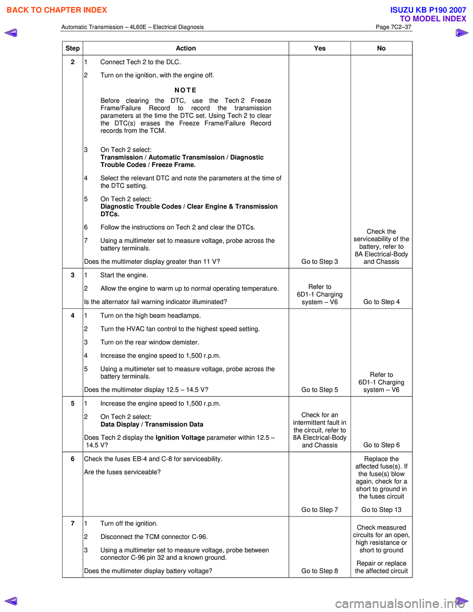
Automatic Transmission – 4L60E – Electrical Diagnosis Page 7C2–37
Step Action Yes No
2 1 Connect Tech 2 to the DLC.
2 Turn on the ignition, with the engine off.
NOTE
Before clearing the DTC, use the Tech 2 Freeze
Frame/Failure Record to record the transmission
parameters at the time the DTC set. Using Tech 2 to clear
the DTC(s) erases the Freeze Frame/Failure Record
records from the TCM.
3 On Tech 2 select: Transmission / Automatic Transmission / Diagnostic
Trouble Codes / Freeze Frame.
4 Select the relevant DTC and note the parameters at the time of the DTC setting.
5 On Tech 2 select:
Diagnostic Trouble Codes / Clear Engine & Transmission
DTCs.
6 Follow the instructions on Tech 2 and clear the DTCs.
7 Using a multimeter set to measure voltage, probe across the battery terminals.
Does the multimeter display greater than 11 V? Go to Step 3 Check the
serviceability of the battery, refer to
8A Electrical-Body and Chassis
3 1 Start the engine.
2 Allow the engine to warm up to normal operating temperature.
Is the alternator fail warning indicator illuminated? Refer to
6D1-1 Charging system – V6 Go to Step 4
4 1 Turn on the high beam headlamps.
2 Turn the HVAC fan control to the highest speed setting.
3 Turn on the rear window demister.
4 Increase the engine speed to 1,500 r.p.m.
5 Using a multimeter set to measure voltage, probe across the battery terminals.
Does the multimeter display 12.5 – 14.5 V? Go to Step 5 Refer to
6D1-1 Charging system – V6
5 1 Increase the engine speed to 1,500 r.p.m.
2 On Tech 2 select: Data Display / Transmission Data
Does Tech 2 display the Ignition Voltage parameter within 12.5 –
14.5 V? Check for an
intermittent fault in the circuit, refer to
8A Electrical-Body
and Chassis Go to Step 6
6
Check the fuses EB-4 and C-8 for serviceability.
Are the fuses serviceable?
Go to Step 7 Replace the
affected fuse(s). If the fuse(s) blow
again, check for a short to ground in the fuses circuit
Go to Step 13
7 1 Turn off the ignition.
2 Disconnect the TCM connector C-96.
3 Using a multimeter set to measure voltage, probe between connector C-96 pin 32 and a known ground.
Does the multimeter display battery voltage? Go to Step 8 Check measured
circuits for an open,
high resistance or short to ground
Repair or replace
the affected circuit
BACK TO CHAPTER INDEX
TO MODEL INDEX
ISUZU KB P190 2007
Page 3832 of 6020
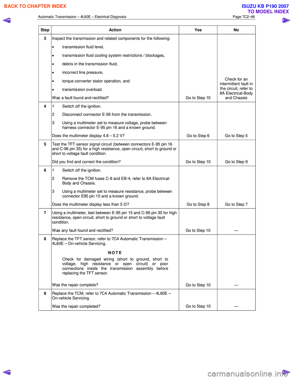
Automatic Transmission – 4L60E – Electrical Diagnosis Page 7C2–46
Step Action Yes No
3 Inspect the transmission and related components for the following:
• transmission fluid level,
• transmission fluid cooling system restrictions / blockages,
• debris in the transmission fluid,
• incorrect line pressure,
• torque converter stator operation, and
• transmission overload.
W as a fault found and rectified? Go to Step 10 Check for an
intermittent fault in
the circuit, refer to
8A Electrical-Body and Chassis
4 1 Switch off the ignition.
2 Disconnect connector E-95 from the transmission.
3 Using a multimeter set to measure voltage, probe between harness connector E-95 pin 16 and a known ground.
Does the multimeter display 4.8 – 5.2 V? Go to Step 6 Go to Step 5
5 Test the TFT sensor signal circuit (between connectors E-95 pin 16
and C-96 pin 35) for a high resistance, open circuit, short to ground or
short to voltage fault condition.
Did you find and correct the condition? Go to Step 10 Go to Step 9
6 1 Switch off the ignition.
2 Remove the TCM fuses C-8 and EB-4, refer to 8A Electrical- Body and Chassis.
3 Using a multimeter set to measure resistance, probe between connector E95 pin 15 and a known ground.
Does the multimeter display less than 5 Ω? Go to Step 8 Go to Step 7
7 Using a multimeter, test between E-95 pin 15 and C-96 pin 30 for high
resistance, open circuit, short to ground or short to voltage fault
condition.
W as any fault found and rectified? Go to Step 10 —
8 Replace the TFT sensor, refer to 7C4 Automatic Transmission –
4L60E – On-vehicle Servicing.
NOTE
Check for damaged wiring (short to ground, short to
voltage, high resistance or open circuit) or poor
connections inside the transmission assembly before
replacing the TFT sensor.
Was the repair complete? Go to Step 10 —
9 Replace the TCM, refer to 7C4 Automatic Transmission – 4L60E –
On-vehicle Servicing
Was the repair completed? Go to Step 10
—
BACK TO CHAPTER INDEX
TO MODEL INDEX
ISUZU KB P190 2007
Page 3957 of 6020
Automatic Transmission – 4L60E – On-vehicle Servicing Page 7C4–44
b Starter motor, refer to 6D1-2 Starting System.
b Rear propeller shaft and for 4WD front propeller shaft, refer to 4A Propeller Shaft.
6 On 4WD vehicle, disconnect the harness two clips from the upper side of the transfer case.
7 From within the starter motor access hole, remove the three bolts (2) attaching the torque converter to the flexplate and discard, refer to Figure 7C4 – 62.
8 Remove the transmission support, refer to 3.7 Transmission Support and Mount.
9 Disconnect the fuel and EVAP pipes three brackets and clips, refer to 6C Fuel System – V6.
Before lowering the transmission take care of
the following:
• Do not strain the harness and connector
as the connector pins could be
permanently damaged.
• Ensure the inlet manifold does not hit the
firewall.
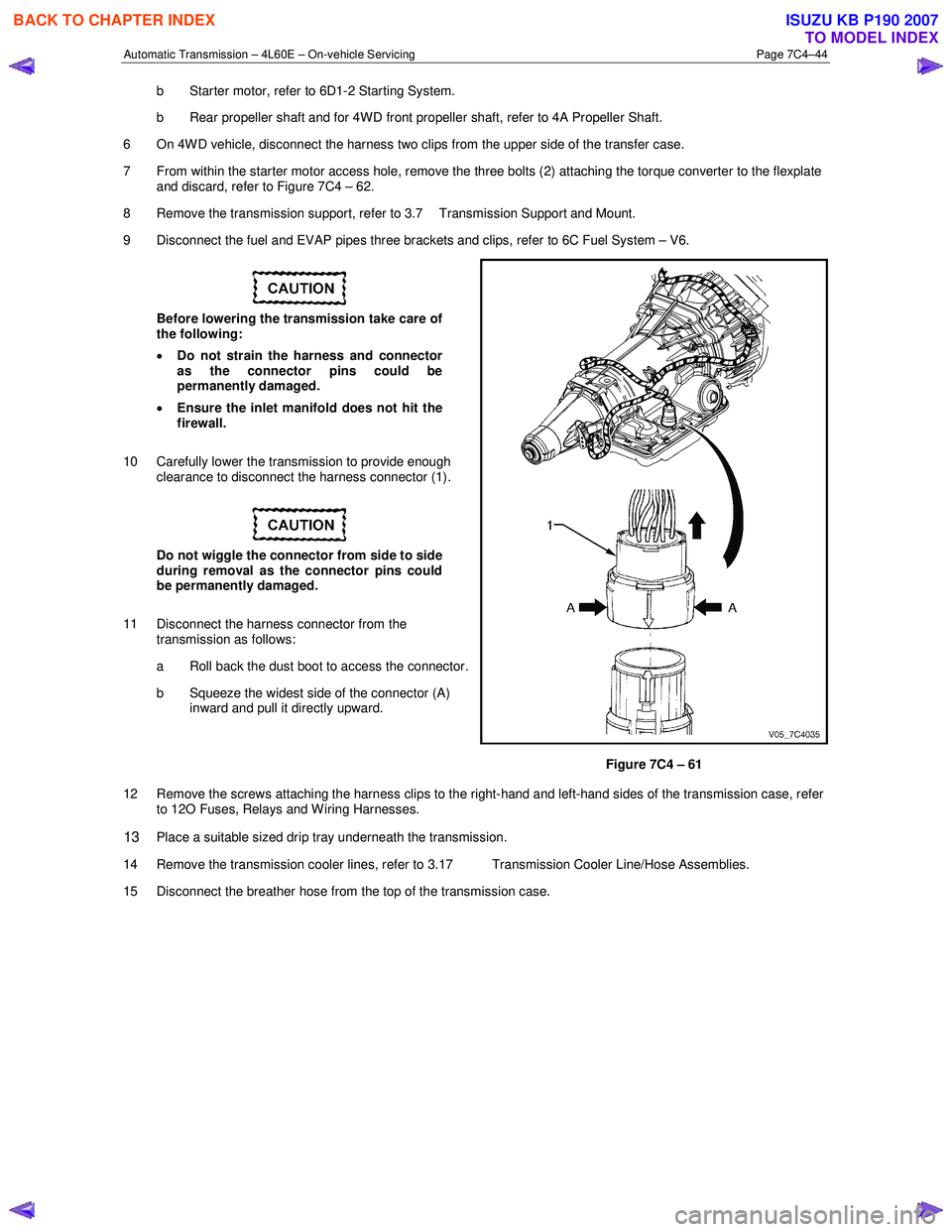
10 Carefully lower the transmission to provide enough clearance to disconnect the harness connector (1).
Do not wiggle the connector from side to side
during removal as the connector pins could
be permanently damaged.
11 Disconnect the harness connector from the transmission as follows:
a Roll back the dust boot to access the connector.
b Squeeze the widest side of the connector (A) inward and pull it directly upward.
Figure 7C4 – 61
12 Remove the screws attaching the harness clips to the right-hand and left-hand sides of the transmission case, refer to 12O Fuses, Relays and W iring Harnesses.
13 Place a suitable sized drip tray underneath the transmission.
14 Remove the transmission cooler lines, refer to 3.17 Transmission Cooler Line/Hose Assemblies.
15 Disconnect the breather hose from the top of the transmission case.
BACK TO CHAPTER INDEX
TO MODEL INDEX
ISUZU KB P190 2007
Page 3959 of 6020
Automatic Transmission – 4L60E – On-vehicle Servicing Page 7C4–46
Reinstall
1 If required on 4W D vehicle, reinstall the transfer case, refer to 7D Transfer Case and Adaptor Housing.
2 Ensure the transmission and the engine mating surfaces are clean and free of burrs.
3 Lubricate the torque converter spigot (7) with a small amount of high temperature wheel bearing grease, refer to Figure 7C4 – 62.
4 Install a new filler tube seal into the transmission case.
Support the transmission while installing the
attaching bolts to avoid damage to the torque
converter and flexplate. Do not have the
transmission hanging.
5 Bring the transmission up to the engine, inserting the filler tube and ensuring the locating dowels completely enter the torque converter housing.
6 Reconnect the breather hose to the top of the transmission case.
NOTE
The bolts attaching the torque converter housing
are facing forward except for the bolt in position ℑ
which is facing rearward.
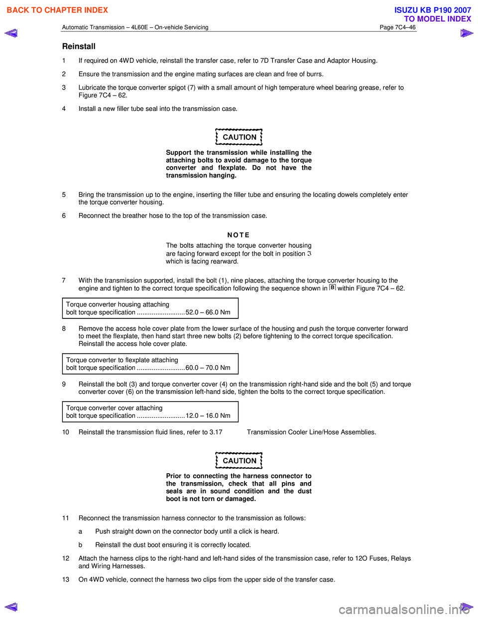
7 With the transmission supported, install the bolt (1), nine places, attaching the torque converter housing to the engine and tighten to the correct torque specification following the sequence shown in
within Figure 7C4 – 62.
Torque converter housing attaching
bolt torque specification .......................... 52.0 – 66.0 Nm
8 Remove the access hole cover plate from the lower surface of the housing and push the torque converter forward to meet the flexplate, then hand start three new bolts (2) before tightening to the correct torque specification.
Reinstall the access hole cover plate.
Torque converter to flexplate attaching
bolt torque specification .......................... 60.0 – 70.0 Nm
9 Reinstall the bolt (3) and torque converter cover (4) on the transmission right-hand side and the bolt (5) and torque converter cover (6) on the transmission left-hand side, tighten the bolts to the correct torque specification.
Torque converter cover attaching
bolt torque specification .......................... 12.0 – 16.0 Nm
10 Reinstall the transmission fluid lines, refer to 3.17 Transmission Cooler Line/Hose Assemblies.
Prior to connecting the harness connector to
the transmission, check that all pins and
seals are in sound condition and the dust
boot is not torn or damaged.
11 Reconnect the transmission harness connector to the transmission as follows: a Push straight down on the connector body until a click is heard.
b Reinstall the dust boot ensuring it is correctly located.
12 Attach the harness clips to the right-hand and left-hand sides of the transmission case, refer to 12O Fuses, Relays and Wiring Harnesses.
13 On 4WD vehicle, connect the harness two clips from the upper side of the transfer case.
BACK TO CHAPTER INDEX
TO MODEL INDEX
ISUZU KB P190 2007
Page 4377 of 6020
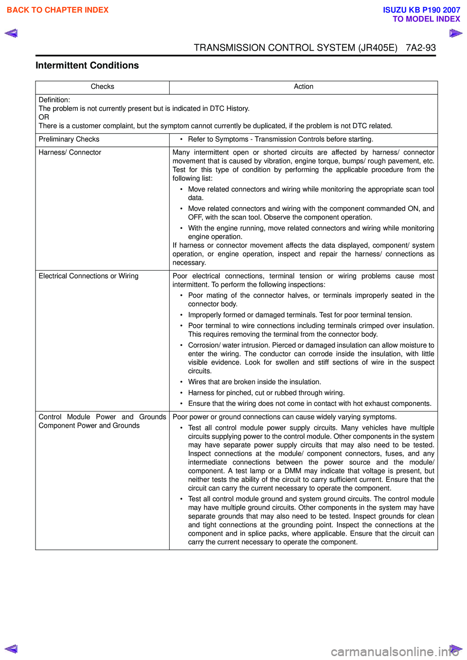
TRANSMISSION CONTROL SYSTEM (JR405E) 7A2-93
Intermittent Conditions
ChecksAction
Definition:
The problem is not currently present but is indicated in DTC History.
OR
There is a customer complaint, but the symptom cannot currently be duplicated, if the problem is not DTC related.
Preliminary Checks • Refer to Symptoms - Transmission Controls before starting.
Harness/ Connector Many intermittent open or shorted circuits are affected by harness/ connector
movement that is caused by vibration, engine torque, bumps/ rough pavement, etc.
Test for this type of condition by performing the applicable procedure from the
following list:
• Move related connectors and wiring while monitoring the appropriate scan tool data.
• Move related connectors and wiring with the component commanded ON, and OFF, with the scan tool. Observe the component operation.
• With the engine running, move related connectors and wiring while monitoring engine operation.
If harness or connector movement affects the data displayed, component/ system
operation, or engine operation, inspect and repair the harness/ connections as
necessary.
Electrical Connections or Wiring Poor electrical connections, terminal tension or wiring problems cause most intermittent. To perform the following inspections:
• Poor mating of the connector halves, or terminals improperly seated in the connector body.
• Improperly formed or damaged terminals. Test for poor terminal tension.
• Poor terminal to wire connections including terminals crimped over insulation. This requires removing the terminal from the connector body.
• Corrosion/ water intrusion. Pierced or damaged insulation can allow moisture to enter the wiring. The conductor can corrode inside the insulation, with little
visible evidence. Look for swollen and stiff sections of wire in the suspect
circuits.
• Wires that are broken inside the insulation.
• Harness for pinched, cut or rubbed through wiring.
• Ensure that the wiring does not come in contact with hot exhaust components.
Control Module Power and Grounds
Component Power and Grounds Poor power or ground connections can cause widely varying symptoms.
• Test all control module power supply circuits. Many vehicles have multiple circuits supplying power to the control module. Other components in the system
may have separate power supply circuits that may also need to be tested.
Inspect connections at the module/ component connectors, fuses, and any
intermediate connections between the power source and the module/
component. A test lamp or a DMM may indicate that voltage is present, but
neither tests the ability of the circuit to carry sufficient current. Ensure that the
circuit can carry the current necessary to operate the component.
• Test all control module ground and system ground circuits. The control module may have multiple ground circuits. Other components in the system may have
separate grounds that may also need to be tested. Inspect grounds for clean
and tight connections at the grounding point. Inspect the connections at the
component and in splice packs, where applicable. Ensure that the circuit can
carry the current necessary to operate the component.
BACK TO CHAPTER INDEX
TO MODEL INDEX
ISUZU KB P190 2007
Page 4942 of 6020
8A-4 ELECTRICAL-BODY AND CHASSIS
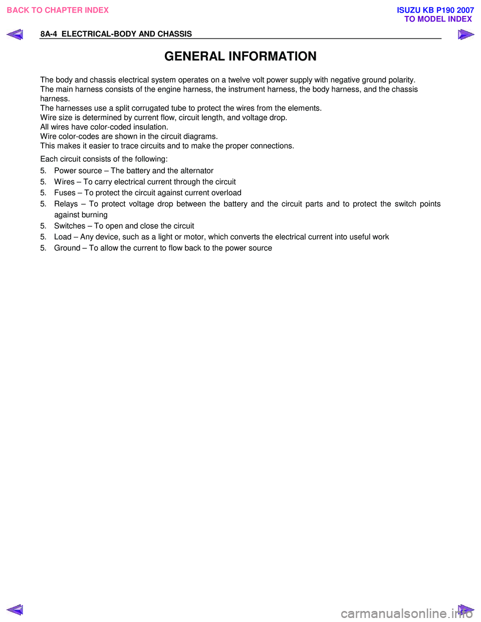
GENERAL INFORMATION
The body and chassis electrical system operates on a twelve volt power supply with negative ground polarity.
The main harness consists of the engine harness, the instrument harness, the body harness, and the chassis
harness.
The harnesses use a split corrugated tube to protect the wires from the elements.
W ire size is determined by current flow, circuit length, and voltage drop.
All wires have color-coded insulation.
W ire color-codes are shown in the circuit diagrams.
This makes it easier to trace circuits and to make the proper connections.
Each circuit consists of the following:
5. Power source – The battery and the alternator
5. W ires – To carry electrical current through the circuit
5. Fuses – To protect the circuit against current overload
5. Relays – To protect voltage drop between the battery and the circuit parts and to protect the switch points against burning
5. Switches – To open and close the circuit
5. Load – Any device, such as a light or motor, which converts the electrical current into useful work
5. Ground – To allow the current to flow back to the power source
BACK TO CHAPTER INDEX TO MODEL INDEXISUZU KB P190 2007
Page 4953 of 6020
ELECTRICAL-BODY AND CHASSIS 8A-15
NormalBlown
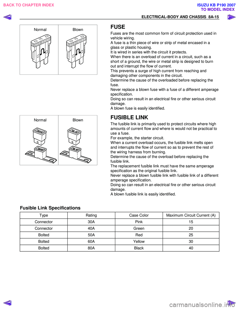
FUSE
Fuses are the most common form of circuit protection used in
vehicle wiring.
A fuse is a thin piece of wire or strip of metal encased in a
glass or plastic housing.
It is wired in series with the circuit it protects.
W hen there is an overload of current in a circuit, such as a
short of a ground, the wire or metal strip is designed to burn
out and interrupt the flow of current.
This prevents a surge of high current from reaching and
damaging other components in the circuit.
Determine the cause of the overloaded before replacing the
fuse.
Never replace a blown fuse with a fuse of a different amperage
specification.
Doing so can result in an electrical fire or other serious circuit
damage.
A blown fuse is easily identified.
Normal Blown
FUSIBLE LINK
The fusible link is primarily used to protect circuits where high
amounts of current flow and where is would not be practical to
use a fuse.
For example, the starter circuit.
W hen a current overload occurs, the fusible link melts open
and interrupts the flow of current so as to prevent the rest of
the wiring harness from burning.
Determine the cause of the overload before replacing the
fusible link.
The replacement fusible link must have the same amperage
specification as the original fusible link.
Never replace a blown fusible link with fusible link of a different
amperage specification.
Doing so can result in an electrical fire or other serious circuit
damage.
A blown fusible link is easily identified.
Fusible Link Specifications
Type Rating Case Color Maximum Circuit Current (A)
Connector 30A Pink 15
Connector 40A Green 20
Bolted 50A Red 25
Bolted 60A Yellow 30
Bolted 80A Black 40
BACK TO CHAPTER INDEX
TO MODEL INDEXISUZU KB P190 2007
Page 5694 of 6020
9A1-12 RESTRAINT CONTROL SYSTEM
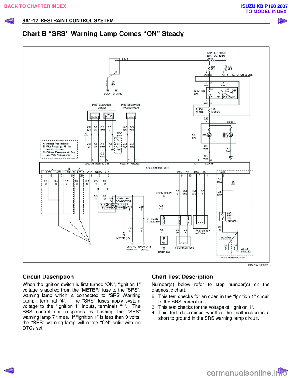
Chart B “SRS” Warning Lamp Comes “ON” Steady
RTW 79ALF000301
Circuit Description
W hen the ignition switch is first turned “ON”, “Ignition 1”
voltage is applied from the “METER” fuse to the “SRS”,
warning lamp which is connected to “SRS W arning
Lamp”, terminal “4”. The “SRS” fuses apply system
voltage to the “Ignition 1” inputs, terminals “1”. The
SRS control unit responds by flashing the “SRS”
warning lamp 7 times. If “Ignition 1” is less than 9 volts,
the “SRS” warning lamp will come “ON” solid with no
DTCs set.
Chart Test Description
Number(s) below refer to step number(s) on the
diagnostic chart:
2. This test checks for an open in the “Ignition 1” circuit to the SRS control unit.
3. This test checks for the voltage of “Ignition 1”.
4. This test determines whether the malfunction is a short to ground in the SRS warning lamp circuit.
BACK TO CHAPTER INDEX TO MODEL INDEX
ISUZU KB P190 2007