2007 ISUZU KB P190 cooling
[x] Cancel search: coolingPage 2500 of 6020
Engine Mechanical – V6 Page 6A1–21
1.4 Engine Construction
Cylinder Block
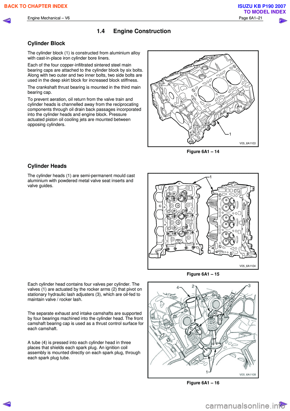
The cylinder block (1) is constructed from aluminium alloy
with cast-in-place iron cylinder bore liners.
Each of the four copper-infiltrated sintered steel main
bearing caps are attached to the cylinder block by six bolts.
Along with two outer and two inner bolts, two side bolts are
used in the deep skirt block for increased block stiffness.
The crankshaft thrust bearing is mounted in the third main
bearing cap.
To prevent aeration, oil return from the valve train and
cylinder heads is channelled away from the reciprocating
components through oil drain back passages incorporated
into the cylinder heads and engine block. Pressure
actuated piston oil cooling jets are mounted between
opposing cylinders.
Figure 6A1 – 14
Cylinder Heads
The cylinder heads (1) are semi-permanent mould cast
aluminium with powdered metal valve seat inserts and
valve guides.
Figure 6A1 – 15
Each cylinder head contains four valves per cylinder. The
valves (1) are actuated by the rocker arms (2) that pivot on
stationary hydraulic lash adjusters (3), which are oil-fed to
maintain valve / rocker lash.
The separate exhaust and intake camshafts are supported
by four bearings machined into the cylinder head. The front
camshaft bearing cap is used as a thrust control surface for
each camshaft.
A tube (4) is pressed into each cylinder head in three
places that shields each spark plug. An ignition coil
assembly is mounted directly on each spark plug, through
each spark plug tube.
Figure 6A1 – 16
BACK TO CHAPTER INDEX
TO MODEL INDEX
ISUZU KB P190 2007
Page 2503 of 6020
Engine Mechanical – V6 Page 6A1–24
1.5 Engine Lubrication System
Lubrication Description
A structural diecast aluminium oil pan is fitted that incorporates an oil suction pipe, an oil deflector and an oil level sensor.
The oil suction pipe is bolted into the oil pan and seals to the bottom of the cylinder block with a gasket. The oil deflector
is bolted to the upper portion of the oil pan and ensures oil supply is maintained under all conditions. The oil level sensor
is mounted through the bottom of the oil pan.
A crankshaft driven gerotor oil pump is mounted to the front of the cylinder block. The pump, which incorporates an
internal pressure-relief valve, draws oil from the oil suction tube through the lower passage in the cylinder block. Oil is
then directed through an upper passage to the left-hand side of the cylinder block where the oil filter adapter is mounted.
The oil filter adapter incorporates a top-access, cartridge style oil filter. The filter is accessed through a screw-on cap tha t
incorporates an oil bypass valve. The oil filter adapter housing incorporates a drain back control valve and a threaded oil
pressure sender. Oil flows through a lower passage within the oil filter adapter and through the oil filter cartridge. Filtered
oil travels back through the upper passage of the adapter and into the engine block.
Oil is then directed up and across the front of the cylinder block, through several drilled passages. These front passages
feed oil to each cylinder head, the passage for the main bearings and piston oil jets, the right-hand and left-hand
secondary idler sprockets and to the primary timing chain tensioner.
Each cylinder head passage directs oil into oiling circuits for the stationary hydraulic lash adjusters (SHLAs) and the
camshaft bearing journals. An additional passage in the cylinder head also directs oil to the secondary timing chain
tensioner.
The oil passage that supplies oil to the main bearings also supplies oil to pressure actuated piston cooling oil jets. Each
oil jet is mounted between opposing cylinder bores and directs oil to the two bores to provide extra cooling and control
piston temperatures.
From the front passages, oil is directed to the front of the block where the right-hand and left-hand intermediate drive
shaft sprockets and the primary timing chain tensioner are mounted. Each camshaft timing chain tensioner relies on a
gasket to maintain an oil reserve after the engine is turned off. All camshaft timing chain tensioners incorporate a small
oil jet to supply an oil spray onto the camshaft timing chain components.
Oil returns to the oil pan, either through the camshaft timing chain area or through the drain back passages on the
outboard walls of the cylinder heads and cylinder block.
1.6 Service Notes
Cleanliness and Care
Throughout this Section, correct cleaning and protection of machined surfaces and friction areas is a part of the repair
procedure. This is considered standard workshop practice, even if not specifically stated.
W hen any internal engine part is serviced, care and cleanliness is extremely important.
W hen components are removed for service, they should be marked, organised or retained in a specific order for
reassembly.
At the time of installation, components should be installed in the same location and with the same mating surface as
when removed.
Any engine is a combination of many machined, honed, polished and lapped surfaces with tolerances that are measured
in thousandths of a millimetre. These surfaces should be covered or protected to avoid component damage.
A liberal coating of clean engine oil should be applied to friction areas during assembly, as the lubrication will protect and
lubricate friction surfaces during the initial engine start-up.
Replacing Engine Gaskets
Re-Using Gaskets and Applying Sealants
• do not reuse any gasket unless specified,
• gaskets that can be reused will be identified in the service procedure, and
• do not apply sealant to any gasket or sealing surface unless specified in the service information.
Separating Components
• Use a rubber mallet to separate components.
• Bump the part sideways to loosen the components.
• Bumping should be done at bends or reinforced areas to prevent distortion of parts.
Cleaning Gasket Surfaces
• W here required, remove all gasket and sealing material from the part using a plastic or wood scraper.
• Care must be used to avoid gouging or scraping the sealing surfaces.
BACK TO CHAPTER INDEX
TO MODEL INDEX
ISUZU KB P190 2007
Page 2516 of 6020
Engine Mechanical – V6 Page 6A1–37
2.13 Coolant in Combustion Chamber
Definition
Excessive white smoke and/or coolant type odour emitted from the exhaust pipe may indicate coolant in the combustion
chamber. Low coolant levels, an inoperative engine cooling fan or a faulty thermostat may lead to an over-temperature
condition which may cause internal engine component damage. A slower than normal cranking speed may indicate
coolant entering the combustion chamber.
1 Remove the spark plugs and inspect for spark plugs saturated by coolant and coolant in the cylinder bore.
2 Inspect by performing a cylinder leakage test, refer to 2.16 Cylinder Leakage Test. During this test, excessive air bubbles in the coolant may indicate a faulty head gasket, cracked cylinder head or cracked cylinder
block.
3 Inspect by performing a cylinder compression test. Two cylinders side-by-side on the cylinder block, with low compression, may indicate a failed cylinder head gasket, refer to 2.15 Engine Compression Test.
Cause Correction
Cracked intake manifold or faulty gasket. Replace components as required, refer to 3.10
Intake Manifold Assembly – Complete.
Faulty cylinder head gasket. Replace the cylinder head gasket, refer to 3.22
Cylinder Head Assembly.
W arped cylinder head. Repair or replace the cylinder heads as required, refer to
3.22 Cylinder Head Assembly.
Cracked cylinder liner or block Repair or replace the cylinder block and components as
required, refer to 4.7 Cylinder Block.
Cylinder head or cylinder block porosity. Repair or replace the cylinder block or cylinder heads as
required, refer to 4.7 Cylinder Block or 3.22
Cylinder Head Assembly.
2.14 Coolant in Engine Oil
Definition
Foamy or discoloured oil or an engine oil overfill condition may indicate coolant entering the engine crankcase. Low
coolant levels, an inoperative engine cooling fan or a faulty thermostat may lead to an over-temperature condition which
may result in engine component damage. Contaminated engine oil and oil filters must be replaced.
1 Inspect the oil for excessive foaming or an overfill condition. Oil diluted by coolant may not correctly lubricate the crankshaft bearings, resulting in component damage, refer to 2.10 Lower Engine Noise, Regardless of Engine
Speed.
2 Perform a cylinder leakage test, refer to 2.16 Cylinder Leakage Test. During this procedure, excessive air bubbles in the engine coolant may indicate a faulty gasket or damaged component.
3 Perform a cylinder compression test. Two cylinders side-by-side on the cylinder block, with low compression, may indicate a failed cylinder head gasket, refer to 2.15 Engine Compression Test.
Cause Correction
Faulty cylinder head gasket. Replace the cylinder head gasket, refer to 3.22
Cylinder Head Assembly.
W arped cylinder head. Repair or replace the cylinder heads as required, refer to
3.22 Cylinder Head Assembly.
Cracked cylinder liner or block Repair or replace the cylinder block and components as
required, refer to 4.7 Cylinder Block.
Cylinder head, cylinder block or intake manifold porosity. Repair or replace the cylinder block, cylinder heads or intake manifold components as required, refer to 4.7
Cylinder Block, 3.22 Cylinder Head
Assembly or 3.10 Intake Manifold Assembly – Complete.
BACK TO CHAPTER INDEX
TO MODEL INDEX
ISUZU KB P190 2007
Page 2518 of 6020

Engine Mechanical – V6 Page 6A1–39
2.16 Cylinder Leakage Test
A leakage test may be performed to measure cylinder/combustion chamber leakage. High cylinder leakage may indicate
one or more of the following:
• worn or burnt valves,
• broken valve springs,
• stuck valve lifters,
• incorrect valve lash/adjustment,
• damaged piston,
• worn piston rings,
• worn or scored cylinder bore,
• damaged cylinder head gasket,
• cracked or damaged cylinder head, or
• cracked or damaged engine block.
1 Disconnect the battery ground negative cable.
2 Remove the spark plugs from all cylinders, refer to 6C1-3 Engine Management – V6 – Service Operations.
3 Rotate the crankshaft to place the piston in the cylinder being tested at top dead centre (TDC) of the compression stroke.
4 Install a commercially available cylinder head leak down tester into the spark plug hole.
NOTE
If required, hold the crankshaft balancer bolt to
prevent the engine from rotating.
5 Apply shop air pressure to the cylinder head leak down tester and adjust according to the manufacturers instructions.
6 Record the cylinder leakage value. Cylinder leakage that exceeds 25 percent is considered excessive and may require component service. In excessive leakage situations, inspect for the following conditions:
• air leakage sounds at the throttle body or air inlet duct that may indicate a worn or burnt intake valve or a
broken valve spring,
• air leakage sounds at the exhaust system tailpipe that may indicate a worn or burnt exhaust valve or a broken
valve spring,
• air leakage sounds from the crankcase, oil level indicator tube, or oil fill tube that may indicate worn piston
rings, a damaged piston, a worn or scored cylinder bore, a damaged engine block or a damaged cylinder
head, or
• air bubbles in the cooling system may indicate a damaged cylinder head or a damaged cylinder head gasket.
7 Perform the leakage test on the remaining cylinders and record the values.
2.17 Engine Oil Consumption Diagnosis
Definition
Excessive oil consumption (not due to leaks) is the use of 3 litres or more of engine oil within 10,000 kilometres. Prior to
performing oil pressure testing, a preliminary inspection of the vehicle should be performed. During the preliminary visual
inspection, the following likely causes of excessive oil usage should be investigated.
Cause Correction
External oil leaks. Refer to 2.18 Engine Oil Leak Diagnosis.
Incorrect oil level or reading of the oil level indicator. Check for the correct oil level, refer to 3.1 Engine Oil.
Incorrect oil viscosity. Replace the engine oil, using the recommended SAE grade
of engine oil, refer to 3.1 Engine Oil.
Continuous high-speed driving or severe usage. Service vehicle more frequently, refer to 0B Lubrication and
Service.
Crankcase ventilation system restricted or malfunctioning. Repair or replace crankcase ventilation system components as required, refer to 6C1-3 Engine Management – V6 –
Service Operations.
BACK TO CHAPTER INDEX
TO MODEL INDEX
ISUZU KB P190 2007
Page 2529 of 6020

Engine Mechanical – V6 Page 6A1–50
Diagnostic Table
Step Action Yes No
1 Did you review the information provided in 2.2 Symptoms, and
perform the required inspections. Go to Step 2 Go to 2.2
Symptoms
2 Confirm the customer complaint. Is there a rumbling noise? Go to Step 3 Refer to Diagnostic
Aids in this Section
3 1 Remove the drive belt, refer to 3.5 Accessory Drive Belt.
2 Operate the engine for no more than 40 seconds.
Does the vibration noise still exist? Accessory drive
system OK.
Go to 4.2
Symptoms, and
restart the diagnosis Go to Step 4
4 Inspect the accessory drive belt for damage, wear, debris build-up or
sections of missing ribs.
Did you find any damage, wear, debris build-up or missing ribs? Go to Step 5 Go to Step 6
5 Install a new accessory drive belt, refer to 3.5 Accessory Drive Belt.
Did you replace the accessory drive belt? Go to Step 10 —
6 Inspect for incorrect, loose, missing or damaged fasteners. Did you find any incorrect, loose, missing or damaged fasteners? Go to Step 7 Go to Step 8
7 Tighten any loose fasteners to the correct torque specification, refer to
6 Torque W rench Specifications.
Replace any incorrect or missing fasteners.
Did you complete the repairs? Go to Step 10 —
8 Inspect the coolant pump for a bent shaft, refer to 6B1 Engine Cooling – V6.
Did you find and repair a bent coolant pump shaft? Go to Step 10 Go to Step 9
9 Inspect for bent, cracked or damaged accessory drive component mounting brackets.
Did you find and repair any bent brackets? Go to Step 10 Refer to Diagnostic
Aids in this Section
10 If required, reinstall the accessory drive belt and operate the system to
confirm the repair.
Did you correct the vibration? Accessory drive
system OK Refer to Diagnostic
Aids in this Section
Drive Belt Falls Off
Definition
The drive belt falls off during normal operation or does not ride correctly on the accessory drive pulleys.
Diagnostic Aids
If the accessory drive belt repeatedly falls off the drive pulleys, this is most likely due to pulley misalignment.
An extra load that is quickly applied and released by an accessory drive component (e.g. A/C compressor) may cause
the accessory drive belt to fall off. In this circumstance, confirm the fault by operating the accessory drive components in
turn, noting which one caused the belt to fall off.
Lack of drive belt tension may also cause the belt to fall off the pulleys. Low drive belt tension could be caused by one of
the following:
• an incorrect drive belt length,
• a faulty drive belt tensioner, or
• a stretched or faulty drive belt.
Test Description
The numbers below refer to steps in the diagnostic table.
2 Confirms the condition of the drive belt. Damage may have occurred to the drive belt when it first fell off or it may have been damaged which caused the belt to fall off.
4 Misalignment of the pulleys may be caused by:
BACK TO CHAPTER INDEX
TO MODEL INDEX
ISUZU KB P190 2007
Page 2566 of 6020
Engine Mechanical – V6 Page 6A1–87
3.14 Crankshaft Front Seal
Replace
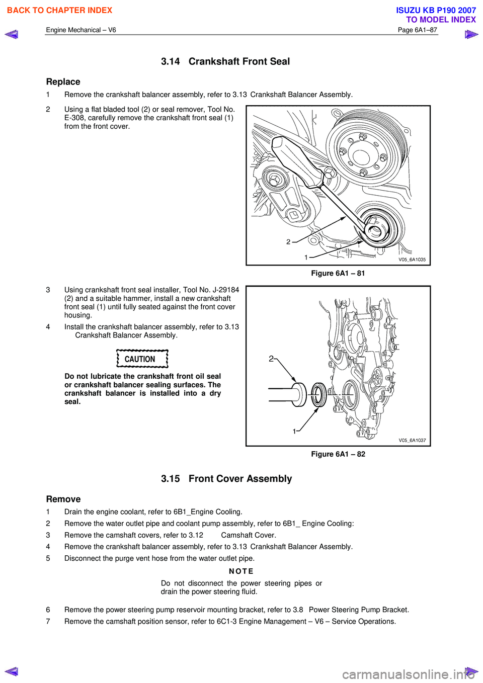
1 Remove the crankshaft balancer assembly, refer to 3.13 Crankshaft Balancer Assembly.
2 Using a flat bladed tool (2) or seal remover, Tool No. E-308, carefully remove the crankshaft front seal (1)
from the front cover.
Figure 6A1 – 81
3 Using crankshaft front seal installer, Tool No. J-29184 (2) and a suitable hammer, install a new crankshaft
front seal (1) until fully seated against the front cover
housing.
4 Install the crankshaft balancer assembly, refer to 3.13 Crankshaft Balancer Assembly.
CAUTION
Do not lubricate the crankshaft front oil seal
or crankshaft balancer sealing surfaces. The
crankshaft balancer is installed into a dry
seal.
Figure 6A1 – 82
3.15 Front Cover Assembly
Remove
1 Drain the engine coolant, refer to 6B1_Engine Cooling.
2 Remove the water outlet pipe and coolant pump assembly, refer to 6B1_ Engine Cooling:
3 Remove the camshaft covers, refer to 3.12 Camshaft Cover.
4 Remove the crankshaft balancer assembly, refer to 3.13 Crankshaft Balancer Assembly.
5 Disconnect the purge vent hose from the water outlet pipe.
NOTE
Do not disconnect the power steering pipes or
drain the power steering fluid.
6 Remove the power steering pump reservoir mounting bracket, refer to 3.8 Power Steering Pump Bracket.
7 Remove the camshaft position sensor, refer to 6C1-3 Engine Management – V6 – Service Operations.
BACK TO CHAPTER INDEX
TO MODEL INDEX
ISUZU KB P190 2007
Page 2569 of 6020
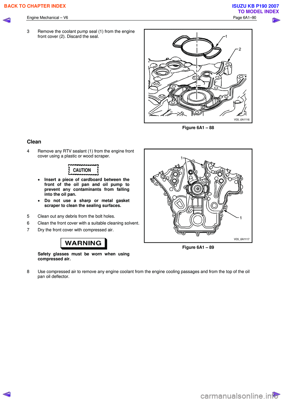
Engine Mechanical – V6 Page 6A1–90
3 Remove the coolant pump seal (1) from the engine
front cover (2). Discard the seal.
Figure 6A1 – 88
Clean
4 Remove any RTV sealant (1) from the engine front cover using a plastic or wood scraper.
CAUTION
• Insert a piece of cardboard between the
front of the oil pan and oil pump to
prevent any contaminants from falling
into the oil pan.
• Do not use a sharp or metal gasket
scraper to clean the sealing surfaces.
5 Clean out any debris from the bolt holes.
6 Clean the front cover with a suitable cleaning solvent.
7 Dry the front cover with compressed air.
Safety glasses must be worn when using
compressed air. Figure 6A1 – 89
8 Use compressed air to remove any engine coolant from the engine cooling passages and from the top of the oil pan oil deflector.
BACK TO CHAPTER INDEX
TO MODEL INDEX
ISUZU KB P190 2007
Page 2572 of 6020
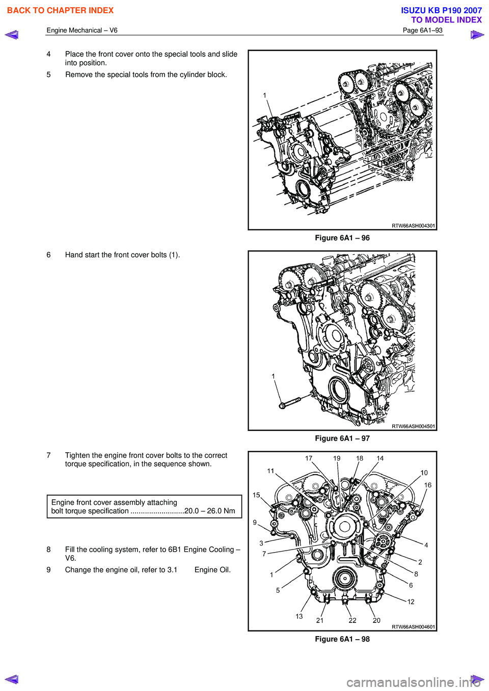
Engine Mechanical – V6 Page 6A1–93
4 Place the front cover onto the special tools and slide
into position.
5 Remove the special tools from the cylinder block.
Figure 6A1 – 96
6 Hand start the front cover bolts (1).
Figure 6A1 – 97
7 Tighten the engine front cover bolts to the correct torque specification, in the sequence shown.
Engine front cover assembly attaching
bolt torque specification ..........................20.0 – 26.0 Nm
8 Fill the cooling system, refer to 6B1 Engine Cooling – V6.
9 Change the engine oil, refer to 3.1 Engine Oil.
Figure 6A1 – 98
BACK TO CHAPTER INDEX
TO MODEL INDEX
ISUZU KB P190 2007