2007 ISUZU KB P190 cooling
[x] Cancel search: coolingPage 3127 of 6020
Engine Mechanical – V6 Page 6A1–350
Page 6A1–350
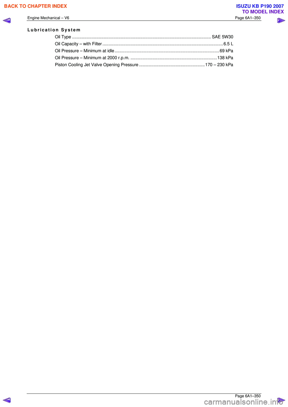
Lubrication System
Oil Type.................................................................................................................. SAE 5 W30
Oil Capacity – with Filter................................................................................................... 6. 5 L
Oil Pressure – Mini mum at idle ......................................................................................69 kPa
Oil Pressure – Minimum at 2000 r.p.m. ....................................................................... 138 kPa
Piston Cooling Jet Valve Op ening Pressure...................................................... 170 – 230 kPa
BACK TO CHAPTER INDEX
TO MODEL INDEX
ISUZU KB P190 2007
Page 3132 of 6020
Engine Mechanical – V6 Page 6A1–355
Page 6A1–355
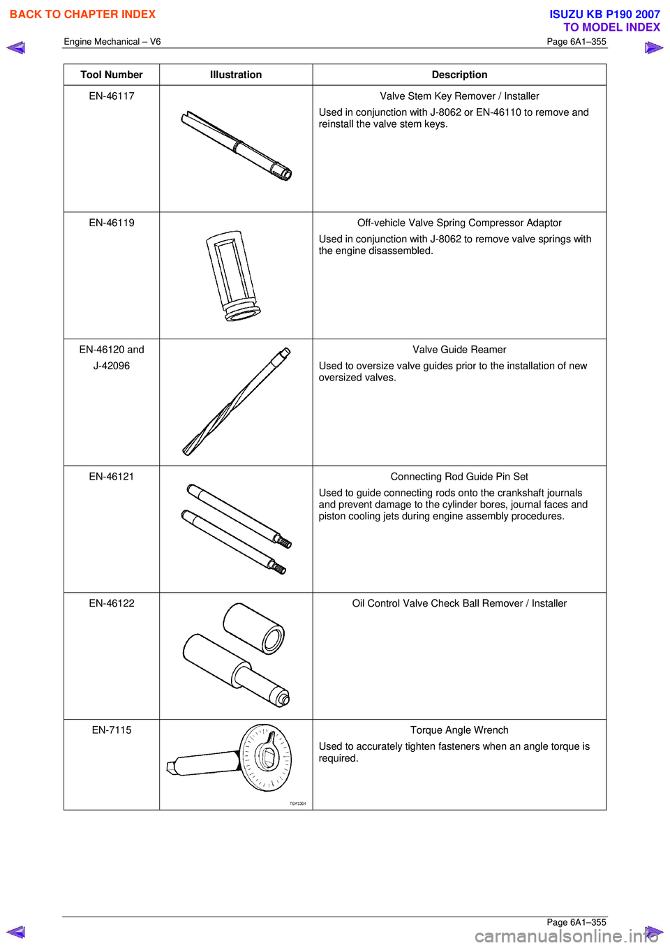
Tool Number Illustration Description
EN-46117
Valve Stem Key Remover / Installer
Used in conjunction with J-8062 or EN-46110 to remove and
reinstall the valve stem keys.
EN-46119
Off-vehicle Valve Spring Compressor Adaptor
Used in conjunction with J-8062 to remove valve springs with
the engine disassembled.
EN-46120 and
J-42096
Valve Guide Reamer
Used to oversize valve guides prior to the installation of new
oversized valves.
EN-46121
Connecting Rod Guide Pin Set
Used to guide connecting rods onto the crankshaft journals
and prevent damage to the cylinder bores, journal faces and
piston cooling jets during engine assembly procedures.
EN-46122
Oil Control Valve Check Ball Remover / Installer
EN-7115
Torque Angle Wrench
Used to accurately tighten fasteners when an angle torque is
required.
BACK TO CHAPTER INDEX
TO MODEL INDEX
ISUZU KB P190 2007
Page 3136 of 6020
Engine Cooling – V6 Engine Page 6B1–1
Section 6B1
Engine Cooling – V6
ATTENTION
Before performing any Service Operation or other procedure described in this Section, refer to 1.1 WARNING,
CAUTION and NOTES for correct workshop practices with regard to safety and/or property damage.
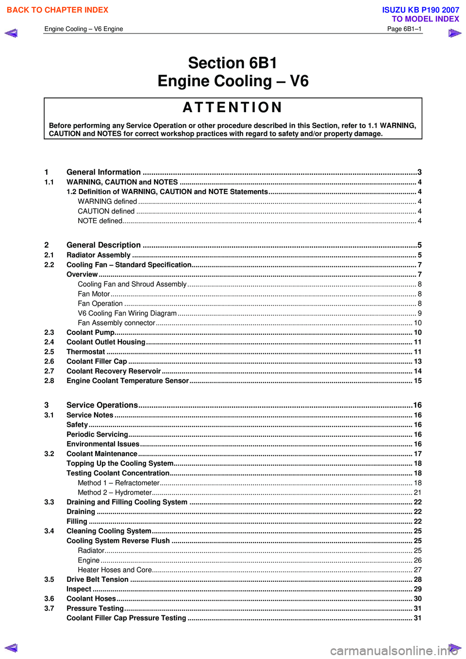
1 General Information ............................................................................................................ ...................3
1.1 WARNING, CAUTION and NOTES ..................................................................................................... ................... 4
1.2 Definition of WARNING, CAUTION and NOTE Statements ......................................................................... .. 4
WARNING defined ............................................................................................................................................. 4
CAUTION defined .............................................................................................................................................. 4
NOTE defined..................................................................................................................................................... 4
2 General Description ............................................................................................................ ...................5
2.1 Radiator Assembly .............................................................................................................. .................................. 5
2.2 Cooling Fan – Standard Specification.................................................................................................................. 7
Overview ................................................................................................................................................................. 7
Cooling Fan and Shroud Assembly ................................................................................................ .................... 8
Fan Motor ........................................................................................................................................................... 8
Fan Operation .................................................................................................................. .................................. 8
V6 Cooling Fan Wiring Diagram .................................................................................................. ....................... 9
Fan Assembly connector .................................................................................................................................. 10
2.3 Coolant Pump....................................................................................................................................................... 10
2.4 Coolant Outlet Housing ......................................................................................................... .............................. 11
2.5 Thermostat ........................................................................................................................................................... 11
2.6 Coolant Filler Cap ............................................................................................................. ................................... 13
2.7 Coolant Recovery Reservoir ..................................................................................................... .......................... 14
2.8 Engine Coolant Temperature Sensor .............................................................................................. ................... 15
3 Service Operations ...............................................................................................................................16
3.1 Service Notes ....................................................................................................................................................... 16
Safety .................................................................................................................................................................... 16
Periodic Servicing............................................................................................................. ................................... 16
Environmental Issues ........................................................................................................... ............................... 16
3.2 Coolant Maintenance ........................................................................................................................................... 17
Topping Up the Cooling System.................................................................................................. ....................... 18
Testing Coolant Concentration........................................................................................................................... 18
Method 1 – Refractometer................................................................................................................................ 18
Method 2 – Hydrometer.................................................................................................................................... 21
3.3 Draining and Filling Cooling System ............................................................................................ ..................... 22
Draining ................................................................................................................................................................ 22
Filling .................................................................................................................................................................... 22
3.4 Cleaning Cooling System ........................................................................................................ ............................ 25
Cooling System Reverse Flush ................................................................................................... ....................... 25
Radiator............................................................................................................................................................ 25
Engine .............................................................................................................................................................. 26
Heater Hoses and Core.......................................................................................................... .......................... 27
3.5 Drive Belt Tension ............................................................................................................................................... 28
Inspect .................................................................................................................................................................. 29
3.6 Coolant Hoses ...................................................................................................................................................... 30
3.7 Pressure Testing ............................................................................................................... ................................... 31
Coolant Filler Cap Pressure Testing ............................................................................................ ...................... 31
BACK TO CHAPTER INDEX
TO MODEL INDEX
ISUZU KB P190 2007
Page 3137 of 6020
Engine Cooling – V6 Engine Page 6B1–2
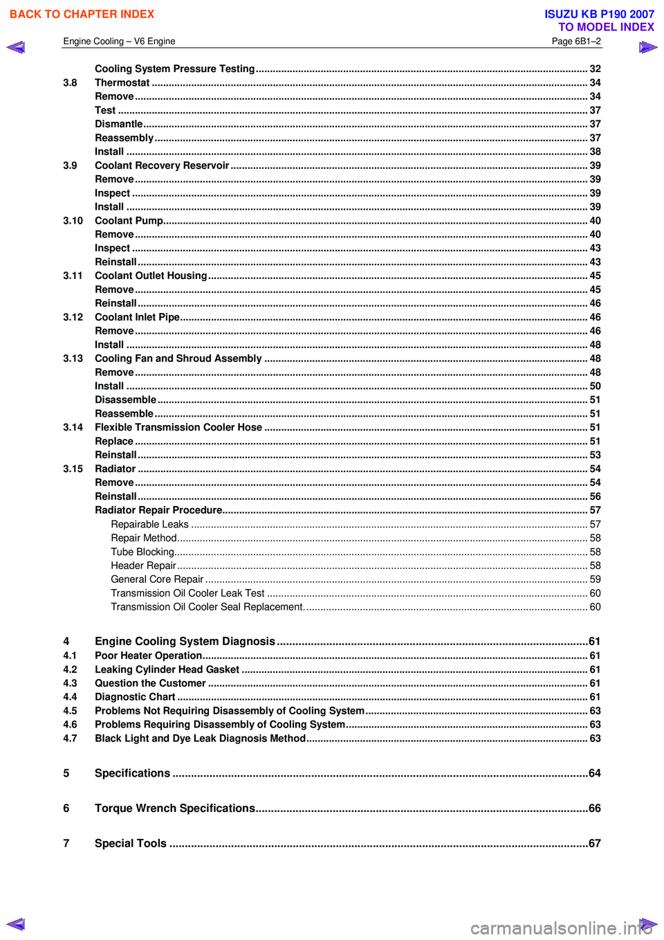
Cooling System Pressure Testing ................................................................................................ ...................... 32
3.8 Thermostat ........................................................................................................................................................... 34
Remove ................................................................................................................................................................. 34
Test ....................................................................................................................................................................... 37
Dismantle ...................................................................................................................... ........................................ 37
Reassembly .......................................................................................................................................................... 37
Install .................................................................................................................................................................... 38
3.9 Coolant Recovery Reservoir ..................................................................................................... .......................... 39
Remove ................................................................................................................................................................. 39
Inspect .................................................................................................................................................................. 39
Install .................................................................................................................................................................... 39
3.10 Coolant Pump................................................................................................................... .................................... 40
Remove ................................................................................................................................................................. 40
Inspect .................................................................................................................................................................. 43
Reinstall ................................................................................................................................................................ 43
3.11 Coolant Outlet Housing ......................................................................................................... .............................. 45
Remove ................................................................................................................................................................. 45
Reinstall ................................................................................................................................................................ 46
3.12 Coolant Inlet Pipe............................................................................................................. .................................... 46
Remove ................................................................................................................................................................. 46
Install .................................................................................................................................................................... 48
3.13 Cooling Fan and Shroud Assembly ................................................................................................ ................... 48
Remove ................................................................................................................................................................. 48
Install .................................................................................................................................................................... 50
Disassemble ......................................................................................................................................................... 51
Reassemble .......................................................................................................................................................... 51
3.14 Flexible Transmission Cooler Hose .............................................................................................. ..................... 51
Replace ................................................................................................................................................................. 51
Reinstall ................................................................................................................................................................ 53
3.15 Radiator ....................................................................................................................... ......................................... 54
Remove ......................................................................................................................... ........................................ 54
Reinstall ................................................................................................................................................................ 56
Radiator Repair Procedure...................................................................................................... ............................ 57
Repairable Leaks ............................................................................................................................................. 57
Repair Method.................................................................................................................................................. 58
Tube Blocking................................................................................................................................................... 58
Header Repair .................................................................................................................. ................................ 58
General Core Repair ............................................................................................................ ............................ 59
Transmission Oil Cooler Leak Test .............................................................................................. .................... 60
Transmission Oil Cooler Seal Replacement. ...................................................................................... .............. 60
4 Engine Cooling System Diagnosis .....................................................................................................61
4.1 Poor Heater Operation......................................................................................................................................... 61
4.2 Leaking Cylinder Head Gasket ................................................................................................... ........................ 61
4.3 Question the Customer ....................................................................................................................................... 61
4.4 Diagnostic Chart .................................................................................................................................................. 61
4.5 Problems Not Requiring Disassembly of Cooling System ........................................................................... .... 63
4.6 Problems Requiring Disassembly of Cooling System ...................................................................................... 63
4.7 Black Light and Dye Leak Diagnosis Method .................................................................................................... 63
5 Specifications .......................................................................................................................................64
6 Torque Wrench Specifications................................................................................................... .........66
7 Special Tools ........................................................................................................................................67
BACK TO CHAPTER INDEX
TO MODEL INDEX
ISUZU KB P190 2007
Page 3138 of 6020
Engine Cooling – V6 Engine Page 6B1–3
1 General Information
The cooling system for the HFV6 engine has been re-designed to accommodate this engine’s unique configuration and
engine cooling performance requirements. The following list is a summary of new and modified components:
• Revised radiator assembly.
• New plumbing including radiator hoses, inlet pipe, heater pipes, heater hoses and heater water valve.
• New rear mount thermostat assembly and thermostat housing.
• New coolant outlet with pressure cap.
• New coolant specification.
• New side chutes and radiator shroud.
• Modified cooling fan operating strategy.
• A four stage cooling fan operating system is used.
The cooling fan motor is controlled by duty signal from the ECM which results in the fan operating from low speed Stage
1), up to high speed (Stage 4).
Operation of the cooling fan is dependant on the engine temperature, vehicle speed, A/C request (where fitted) and A/C
system pressure. Refer to 6C1 – 1 Engine management general information.
BACK TO CHAPTER INDEX
TO MODEL INDEX
ISUZU KB P190 2007
Page 3139 of 6020
Engine Cooling – V6 Engine Page 6B1–4
1.1 WARNING, CAUTION and NOTES
This Section contains various W ARNINGS, CAUTIONS and NOTE statements that you must observe carefully to reduce
the risk of death or injury during service, repair procedures or vehicle operation. Incorrect service or repair procedures
may damage the vehicle or cause operational faults. W ARNINGS, CAUTION and NOTE statements are not exhaustive.
HOLDEN LTD can not possibly warn of all the potentially hazardous consequences of failure to follow these instructions.
1.2 Definition of WARNING, CAUTION and NOTE Statements
Diagnosis and repair procedures in this Section contain both general and specific W ARNING, CAUTION and NOTE
statements. HOLDEN LTD is dedicated to the presentation of service information that helps the technician to diagnose
and repair the systems necessary for proper operation of the vehicle. Certain procedures may present a hazard to the
technician if they are not followed in the recommended manner. W ARNING, CAUTION and NOTE statements are
designed to help prevent these hazards from occurring, but not all hazards can be foreseen.
WARNING defined
A W ARNING statement immediately precedes an operating procedure or maintenance practice which, if not correctly
followed, could result in death or injury. A W ARNING statement alerts you to take necessary action or not to take a
prohibited action. If a W ARNING statement is ignored, the following consequences may occur:
• Death or injury to the technician or other personnel working on the vehicle,
• Death or injury to other people in or near the workplace area, and / or
• Death or injury to the driver / or passenger(s) of the vehicle or other people, if the vehicle has been improperly
repaired.
CAUTION defined
A CAUTION statement immediately precedes an operating procedure or maintenance practice which, if not correctly
followed, could result in damage to or destruction of equipment, or corruption of data. If a CAUTION statement is ignored,
the following consequences may occur:
• Damage to the vehicle,
• Unnecessary vehicle repairs or component replacement,
• Faulty operation or performance of any system or component being repaired,
• Damage to any system or components which depend on the proper operation of the system or component being
repaired,
• Faulty operation or performance of any systems or components which depend on the proper operation or
performance of the system or component under repair,
• Damage to fasteners, basic tools or special tools and / or
• Leakage of coolant, lubricant or other vital fluids.
NOTE defined
A NOTE statement immediately precedes or follows an operating procedure, maintenance practice or condition that
requires highlighting. A NOTE statement also emphasises necessary characteristics of a diagnostic or repair procedure.
A NOTE statement is designed to:
• Clarify a procedure,
• Present additional information for accomplishing a procedure,
• Give insight into the reasons for performing a procedure in the recommended manner, and / or
Present information that gives the technician the benefit of past experience in accomplishing a procedure with greater
ease.
BACK TO CHAPTER INDEX
TO MODEL INDEX
ISUZU KB P190 2007
Page 3140 of 6020
Engine Cooling – V6 Engine Page 6B1–5
2 General Description
2.1 Radiator Assembly
The radiator has an aluminium core and is of the cross-flow design. Plastic side tanks are attached to the core by clinch
tabs. The clinch tabs are formed as part of the core assembly.
The lower frame of the radiator assembly is attached to the vehicle frame by two bolts supported in rubber mounts, pegs
are attached to the upper area of each side tank. These pegs are used to support the radiator with two rubber insert
mounting brackets.
A high temperature rubber seal is used to seal the mating surface between the core and each side tank. The seal(s)
must be replaced any time the side tank is removed from the core.
NOTE
The radiator core side tanks or transmission oil
cooler cannot be replaced separately. If there is a
fault with any of these components, the radiator
assembly must be replaced. Small core repairs
may be made using an aluminised silicon based
liquid repair agent. Refer to 3.15 Radiator in
this Section.
For vehicles with automatic transmission, a transmission oil cooler is located in the right-hand side radiator tank. The
cooler pipes from and to the transmission are connected to the oil cooler flexible hoses by means of quick connect
fittings.
The cooling fan motor is attached by three screws to the one-piece plastic fan shroud. In turn, the fan shroud is mounted
to the rear of the radiator and is located and supported by two bolts and two locating tabs. The upper clips lock the fan
shroud in place and can be released by hand to facilitate fan shroud removal. The shroud must be removed to allow fan
motor and blade assembly removal.
One harness connector is mounted to the upper section of the fan shroud allowing the fan motor and blade assemblies
to be removed individually from the shroud. The fan motor and blade is balanced as an assembly. These two
components are serviced only as a unit and are not to be separated.
The shroud, fan assembly and transmission cooler hoses can be removed and installed individually from the vehicle. For
removal and installation procedures, refer to 3.13Cooling Fan and Shroud Assembly, 3.14 Flexible Transmission
Cooler Hose and 3.15 Radiator in this Section.
BACK TO CHAPTER INDEX
TO MODEL INDEX
ISUZU KB P190 2007
Page 3141 of 6020
Engine Cooling – V6 Engine Page 6B1–6
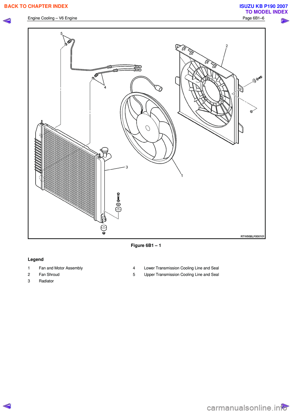
Figure 6B1 – 1
Legend
1 Fan and Motor Assembly
2 Fan Shroud
3 Radiator 4 Lower Transmission Cooling Line and Seal
5 Upper Transmission Cooling Line and Seal
BACK TO CHAPTER INDEX
TO MODEL INDEX
ISUZU KB P190 2007