2007 ISUZU KB P190 cooling
[x] Cancel search: coolingPage 2775 of 6020
Engine Mechanical – V6 Page 6A1–296
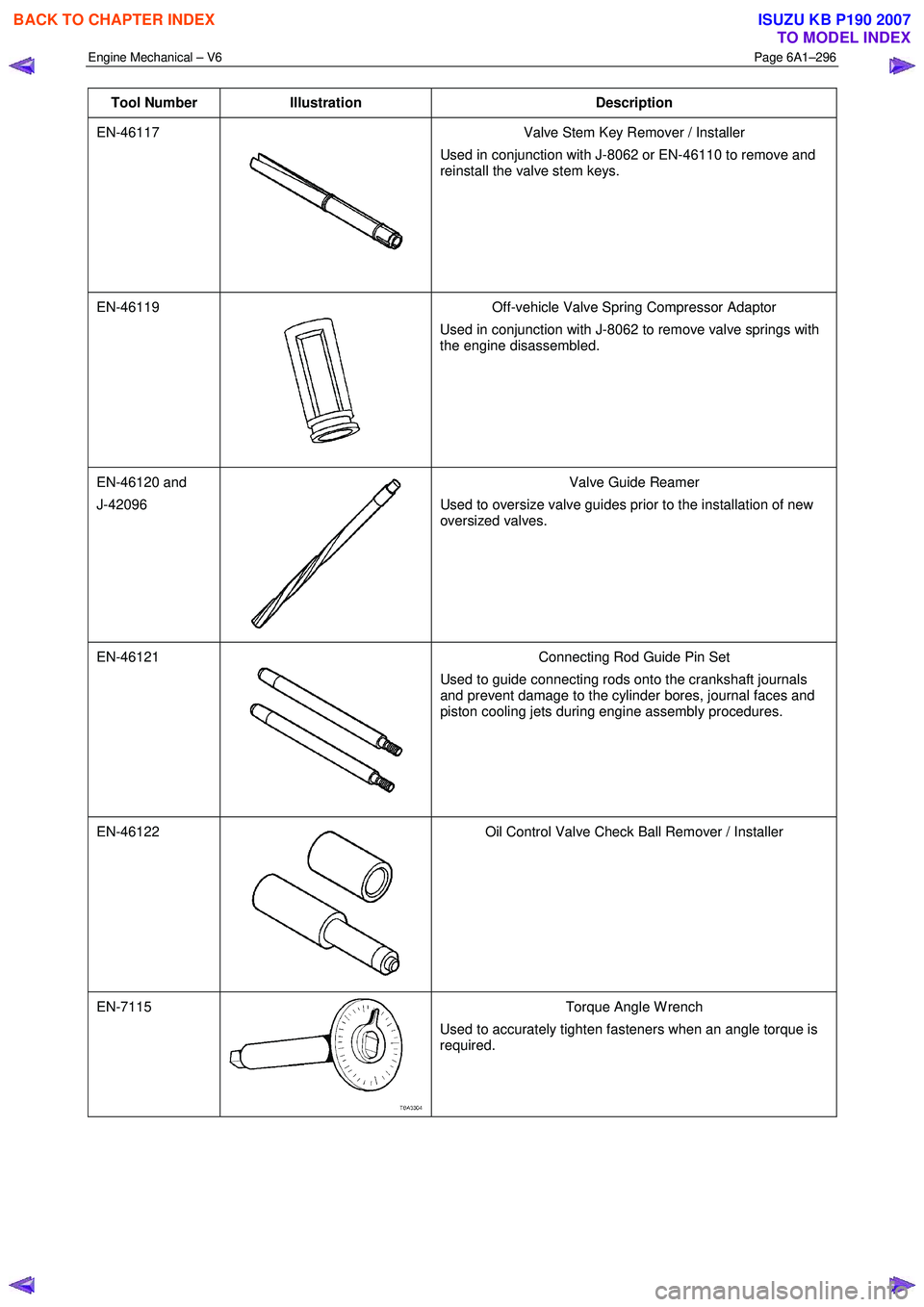
Tool Number Illustration Description
EN-46117
Valve Stem Key Remover / Installer
Used in conjunction with J-8062 or EN-46110 to remove and
reinstall the valve stem keys.
EN-46119
Off-vehicle Valve Spring Compressor Adaptor
Used in conjunction with J-8062 to remove valve springs with
the engine disassembled.
EN-46120 and
J-42096
Valve Guide Reamer
Used to oversize valve guides prior to the installation of new
oversized valves.
EN-46121
Connecting Rod Guide Pin Set
Used to guide connecting rods onto the crankshaft journals
and prevent damage to the cylinder bores, journal faces and
piston cooling jets during engine assembly procedures.
EN-46122
Oil Control Valve Check Ball Remover / Installer
EN-7115 Torque Angle W rench
Used to accurately tighten fasteners when an angle torque is
required.
BACK TO CHAPTER INDEX
TO MODEL INDEX
ISUZU KB P190 2007
Page 2799 of 6020
Engine Mechanical – V6 Page 6A1–22
Page 6A1–22
1.4 Engine Construction
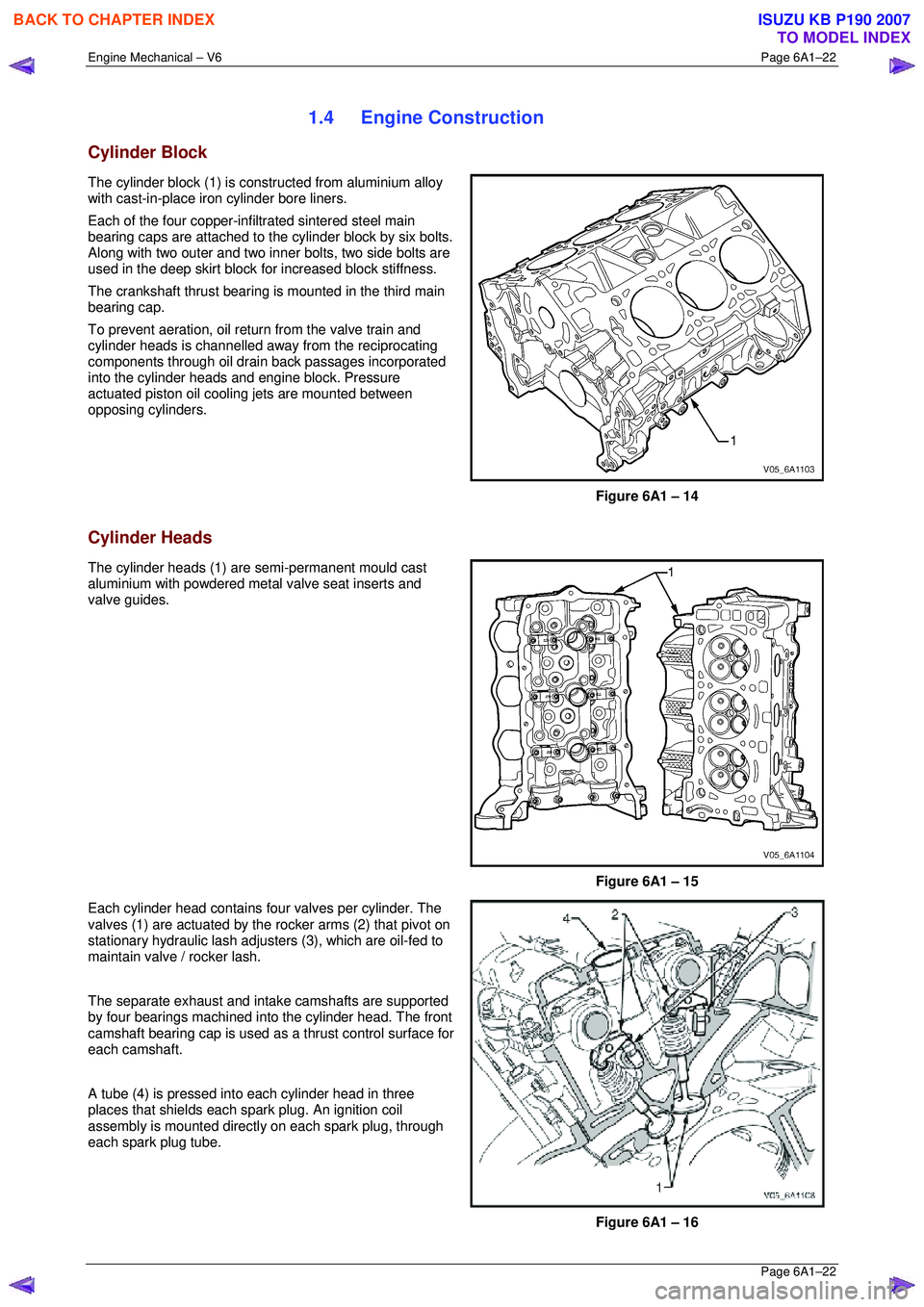
Cylinder Block
The cylinder block (1) is constructed from aluminium alloy
with cast-in-place iron cylinder bore liners.
Each of the four copper-inf iltrated sintered steel main
bearing caps are attached to the cylinder block by six bolts.
Along with two outer and two inner bolts, two side bolts are
used in the deep skirt block fo r increased block stiffness.
The crankshaft thrust bearing is mounted in the third main
bearing cap.
To prevent aeration, oil retu rn from the valve train and
cylinder heads is channelled away from the reciprocating
components through oil drain back passages incorporated
into the cylinder heads and engine block. Pressure
actuated piston oil cooling jets are mounted between
opposing cylinders.
Figure 6A1 – 14
Cylinder Heads
The cylinder heads (1) are semi-permanent mould cast
aluminium with powdered metal valve seat inserts and
valve guides.
Figure 6A1 – 15
Each cylinder head contains four valves per cylinder. The
valves (1) are actuated by the rocker arms (2) that pivot on
stationary hydraulic lash adjuste rs (3), which are oil-fed to
maintain valve / rocker lash.
The separate exhaust and intake camshafts are supported
by four bearings machined into the cylinder head. The front
camshaft bearing cap is used as a thrust control surface for
each camshaft.
A tube (4) is pressed into each cylinder head in three
places that shields each spark plug. An ignition coil
assembly is mounted directly on each spark plug, through
each spark plug tube.
Figure 6A1 – 16
BACK TO CHAPTER INDEX
TO MODEL INDEX
ISUZU KB P190 2007
Page 2802 of 6020
Engine Mechanical – V6 Page 6A1–25
Page 6A1–25
1.5 Engine Lubrication System
Lubrication Description
A structural diecast aluminium oil pan is fitted that incorporates an oil suction pipe, an oil deflector and an oil level
sensor. The oil suction pipe is bolted in to the oil pan and seals to the bottom of the cylinder block with a gasket. The oil
deflector is bolted to the upper portion of the oil pan and ensures oil supply is maintained under all conditions. The oil
level sensor is mounted thr ough the bottom of the oil pan.
A crankshaft driven gerotor oil pump is mounted to the front of the cylinder block. The pump, which incorporates an
internal pressure-relief valve, draws oil from the oil sucti on tube through the lower passage in the cylinder block. Oil is
then directed through an upper passage to the left-hand side of the cylinder block where the oil filter adapter is mounted.
The oil filter adapter incorporat es a top-access, cartridge style oil filter. The filter is accessed through a screw-on cap tha t
incorporates an oil bypass valve. The o il filter adapter housing incorporates a drain back control valve and a threaded oil
pressure sender. Oil flows through a lower passage within the oil filter adapter and through the o il filter cartridge. Filtered
oil travels back through the upper passage of the adapter and into the engine block.
Oil is then directed up and across the front of the cylinder block, through several drilled passages. These front passages
feed oil to each cylinder head, the passage for the main bearings and piston oil jets, the right-hand and left-hand
secondary idler sprockets and to t he primary timing chain tensioner.
Each cylinder head passage directs oil into oiling circuits for the stationary hydraulic la sh adjusters (SHLAs) and the
camshaft bearing journals. An additional passage in the cy linder head also directs oil to the secondary timing chain
tensioner.
The oil passage that supplies oil to the main bearings also s upplies oil to pressure actuated piston cooling oil jets. Each
oil jet is mounted between opposing cylinder bores and directs oil to the two bores to provide extra cooling and control
piston temperatures.
From the front passages, oil is directed to the front of the block where t he right-hand and left-hand intermediate drive
shaft sprockets and the primary timing chain tensioner are mounted. Each camshaft timing chain tensioner relies on a
gasket to maintain an oil rese rve after the engine is turned off. All camshaft timing chain tensioners incorporate a small
oil jet to supply an oil spray onto the camshaft timing chain components.
Oil returns to the oil pan, either through the camshaft timing chain area or through the drain back passages on the
outboard walls of the cylinder heads and cylinder block.
BACK TO CHAPTER INDEX
TO MODEL INDEX
ISUZU KB P190 2007
Page 2820 of 6020
Engine Mechanical – V6 Page 6A1–43
Page 6A1–43
2.13 Coolant in Combustion Chamber
Definition
Excessive white smoke and/or coolant type odour emitted from the exhaust pipe may indicate coolant in the combustion
chamber. Low coolant levels, an inoperativ e engine cooling fan or a faulty thermostat may lead to an over-temperature
condition which may cause internal engine component damage. A slower than normal cranking speed may indicate
coolant entering the combustion chamber.
1 Remove the spark plugs and inspect for spark plugs sa turated by coolant and coolant in the cylinder bore.
2 Inspect by performing a cylinder leakage test, refer to 2.16 Cylinder Leakage Test. During this test, excessive air
bubbles in the coolant may indicate a faulty head ga sket, cracked cylinder head or cracked cylinder block.
3 Inspect by performing a cylinder compression test. Two cylinders side-by-side on the cylinder block, with low
compression, may indicate a fa iled cylinder head gasket, refer to 2.15 Engine Compression Test.
Cause Correction
Cracked intake manifold or faulty gasket. Replace components as required, refer to 3.10 Intake
Manifold Assembly – Complete.
Faulty cylinder head gasket. Replace the cylinder head gasket, refer to 3.22 Cylinder
Head Assembly.
Warped cylinder head. Repair or replace the cylinder heads as required, refer to
3.22 Cylinder Head Assembly.
Cracked cylinder liner or block Repair or replace the cylinder block and components as
required, refer to 4.7 Cylinder Block.
Cylinder head or cylinder block porosity. Repair or replace the cylinder block or cylinder heads as
required, refer to 4.7 Cylinder Block or 3.22 Cylinder Head
Assembly.
BACK TO CHAPTER INDEX
TO MODEL INDEX
ISUZU KB P190 2007
Page 2823 of 6020
Engine Mechanical – V6 Page 6A1–46
Page 6A1–46
2.16 Cylinder Leakage Test
A leakage test may be performed to measure cylinder/combustion chamber leakage. High cylinder leakage may indicate
one or more of the following:
• worn or burnt valves,
• broken valve springs,
• stuck valve lifters,
• incorrect valve lash/adjustment,
• damaged piston,
• worn piston rings,
• worn or scored cylinder bore,
• damaged cylinder head gasket,
• cracked or damaged cylinder head, or
• cracked or damaged engine block.
1 Disconnect the battery ground negative cable.
2 Remove the spark plugs from all cylinders, refer to Section 6C1-3 Engine Management – V6 – Service Operations.
3 Rotate the crankshaft to place the piston in the cyli nder being tested at top dead centre (TDC) of the compression
stroke.
4 Install a commercially available cylinder head leak down tester into the spark plug hole.
NOTE
If required, hold the crankshaft balancer bolt to
prevent the engine from rotating.
5 Apply shop air pressure to the cylinder head leak dow n tester and adjust according to the manufacturers
instructions.
6 Record the cylinder leakage value. Cylinder leakage t hat exceeds 25 percent is considered excessive and may
require component service. In excessive leakage situations, inspect for the following conditions:
• air leakage sounds at the throttle body or air inlet duct that may indicate a worn or burnt intake valve or a
broken valve spring,
• air leakage sounds at the exhaust system tailpipe that may indicate a worn or burnt exhaust valve or a broken
valve spring,
• air leakage sounds from the crankcase, oil level indicator tube, or oil fill tube that may indicate worn piston
rings, a damaged piston, a worn or scored cylinder bore, a damaged engine block or a damaged cylinder
head, or
• air bubbles in the cooling system may indicate a damaged cylinder head or a damaged cylinder head gasket.
7 Perform the leakage test on the rema ining cylinders and record the values.
BACK TO CHAPTER INDEX
TO MODEL INDEX
ISUZU KB P190 2007
Page 2838 of 6020
Engine Mechanical – V6 Page 6A1–61
Page 6A1–61
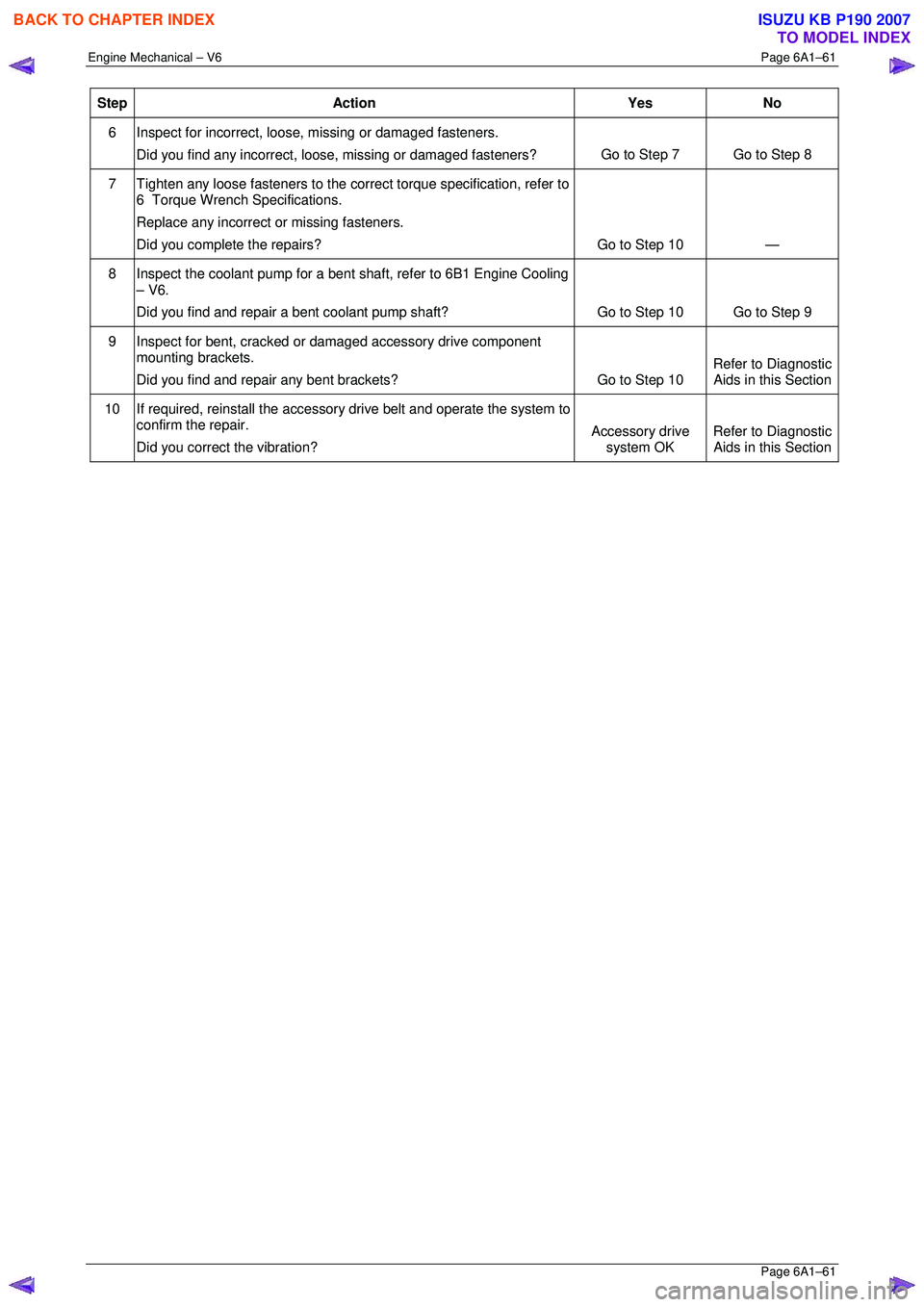
Step Action Yes No
6 Inspect for incorrect, loose, missing or damaged fasteners.
Did you find any incorrect, loose, missing or damaged fasteners? Go to Step 7 Go to Step 8
7
Tighten any loose fasteners to the corre ct torque specification, refer to
6 Torque Wrench Specifications.
Replace any incorrect or missing fasteners.
Did you complete the repairs? Go to Step 10 —
8
Inspect the coolant pump for a bent shaft, refer to 6B1 Engine Cooling
– V6.
Did you find and repair a bent coolant pump shaft? Go to Step 10 Go to Step 9
9
Inspect for bent, cracked or damaged accessory drive component
mounting brackets.
Did you find and repair any bent brackets? Go to Step 10 Refer to Diagnostic
Aids in this Section
10 If required, reinstall the accessory drive belt and operate the system to
confirm the repair.
Did you correct the vibration? Accessory drive
system OK Refer to Diagnostic
Aids in this Section
BACK TO CHAPTER INDEX
TO MODEL INDEX
ISUZU KB P190 2007
Page 2881 of 6020
Engine Mechanical – V6 Page 6A1–104
Page 6A1–104
3.15 Front Cover Assembly
Remove
1 Drain the engine coolant, refer to Section 6B1 Engine Cooling.
2 Remove the water outlet pipe and coolant pump assembly, refer to Section 6B1 Engine Cooling:
3 Remove the camsha ft covers, refer to 3.12 Camshaft Cover .
4 Remove the crankshaft bal ancer assembly, refer to 3.13 Crankshaft Balancer Assembly .
5 Disconnect the purge vent hose from the water outlet pipe.
NOTE
Do not disconnect the power steering pipes or
drain the power steering fluid.
6 Remove the power steering pump reservoir mounting bracket, refer to 3.8 Power Steering Pump Bracket.
7 Remove the camshaft position sensor, refer to Section 6C1-3 Engine Management – V6 – Service Operations.
NOTE
Do not disconnect the A/C compressor pipes.
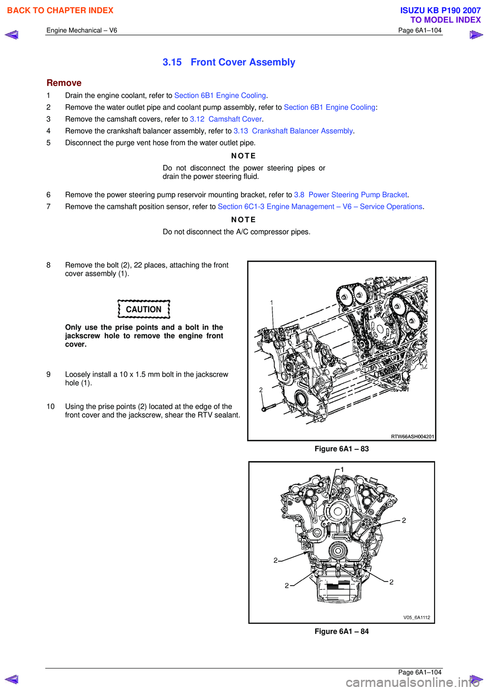
8 Remove the bolt (2), 22 places, attaching the front cover assembly (1).
CAUTION
Only use the prise points and a bolt in the
jackscrew hole to remove the engine front
cover.
9 Loosely install a 10 x 1.5 mm bolt in the jackscrew hole (1).
10 Using the prise points (2) located at the edge of the
front cover and the jackscrew, shear the RTV sealant.
Figure 6A1 – 83
Figure 6A1 – 84
BACK TO CHAPTER INDEX
TO MODEL INDEX
ISUZU KB P190 2007
Page 2883 of 6020
Engine Mechanical – V6 Page 6A1–106
Page 6A1–106
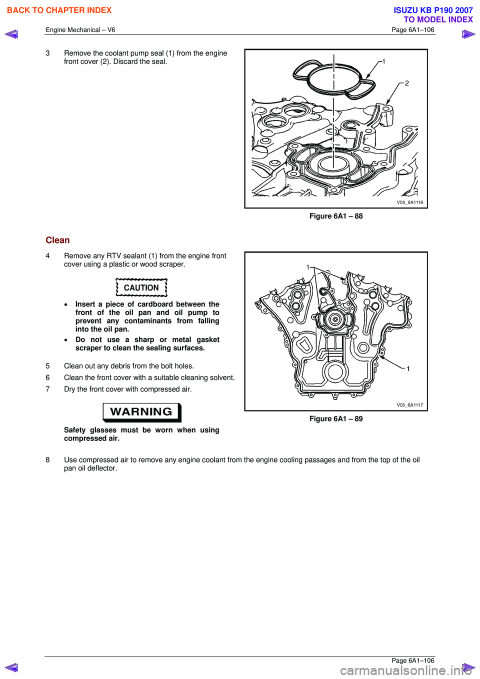
3 Remove the coolant pump seal (1) from the engine
front cover (2). Discard the seal.
Figure 6A1 – 88
Clean
4 Remove any RTV sealant (1) from the engine front cover using a plastic or wood scraper.
CAUTION
• Insert a piece of cardboard between the
front of the oil pan and oil pump to
prevent any contaminants from falling
into the oil pan.
• Do not use a sharp or metal gasket
scraper to clean the sealing surfaces.
5 Clean out any debris from the bolt holes.
6 Clean the front cover with a suitable cleaning solvent.
7 Dry the front cover with compressed air.
Safety glasses must be worn when using
compressed air.
Figure 6A1 – 89
8 Use compressed air to remove any engine coolant from the engine cooling passages and from the top of the oil
pan oil deflector.
BACK TO CHAPTER INDEX
TO MODEL INDEX
ISUZU KB P190 2007