2007 ISUZU KB P190 ignition
[x] Cancel search: ignitionPage 5585 of 6020
Cruise Control – HFV6 Page 8C–7
Activated and Deactivated
When the cruise control is enabled, the vehicle speed must be above 40 km/h and the cruise control switch assembly
pressed to SET–COAST, the cruise control will be activated and the vehicle will maintain the set speed. When
deactivated by the methods described within this section, the vehicle will no longer maintain the set speed, but the cruise
control will still be engaged.
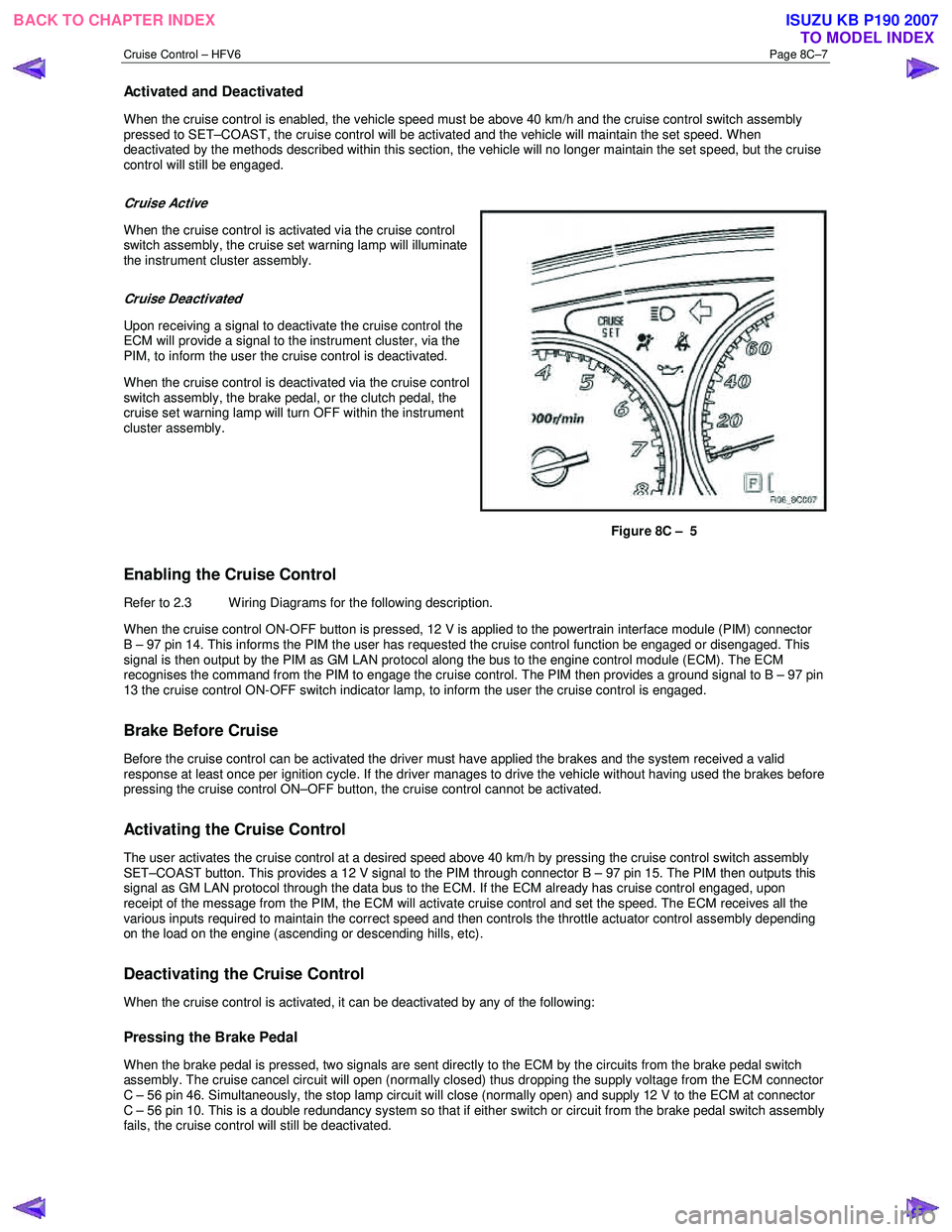
Cruise Active
When the cruise control is activated via the cruise control
switch assembly, the cruise set warning lamp will illuminate
the instrument cluster assembly.
Cruise Deactivated
Upon receiving a signal to deactivate the cruise control the
ECM will provide a signal to the instrument cluster, via the
PIM, to inform the user the cruise control is deactivated.
When the cruise control is deactivated via the cruise control
switch assembly, the brake pedal, or the clutch pedal, the
cruise set warning lamp will turn OFF within the instrument
cluster assembly.
Figure 8C – 5
Enabling the Cruise Control
Refer to 2.3 Wiring Diagrams for the following description.
W hen the cruise control ON-OFF button is pressed, 12 V is applied to the powertrain interface module (PIM) connector
B – 97 pin 14. This informs the PIM the user has requested the cruise control function be engaged or disengaged. This
signal is then output by the PIM as GM LAN protocol along the bus to the engine control module (ECM). The ECM
recognises the command from the PIM to engage the cruise control. The PIM then provides a ground signal to B – 97 pin
13 the cruise control ON-OFF switch indicator lamp, to inform the user the cruise control is engaged.
Brake Before Cruise
Before the cruise control can be activated the driver must have applied the brakes and the system received a valid
response at least once per ignition cycle. If the driver manages to drive the vehicle without having used the brakes before
pressing the cruise control ON–OFF button, the cruise control cannot be activated.
Activating the Cruise Control
The user activates the cruise control at a desired speed above 40 km/h by pressing the cruise control switch assembly
SET–COAST button. This provides a 12 V signal to the PIM through connector B – 97 pin 15. The PIM then outputs this
signal as GM LAN protocol through the data bus to the ECM. If the ECM already has cruise control engaged, upon
receipt of the message from the PIM, the ECM will activate cruise control and set the speed. The ECM receives all the
various inputs required to maintain the correct speed and then controls the throttle actuator control assembly depending
on the load on the engine (ascending or descending hills, etc).
Deactivating the Cruise Control
When the cruise control is activated, it can be deactivated by any of the following:
Pressing the Brake Pedal
When the brake pedal is pressed, two signals are sent directly to the ECM by the circuits from the brake pedal switch
assembly. The cruise cancel circuit will open (normally closed) thus dropping the supply voltage from the ECM connector
C – 56 pin 46. Simultaneously, the stop lamp circuit will close (normally open) and supply 12 V to the ECM at connector
C – 56 pin 10. This is a double redundancy system so that if either switch or circuit from the brake pedal switch assembly
fails, the cruise control will still be deactivated.
BACK TO CHAPTER INDEX TO MODEL INDEXISUZU KB P190 2007
Page 5588 of 6020
Cruise Control – HFV6 Page 8C–10
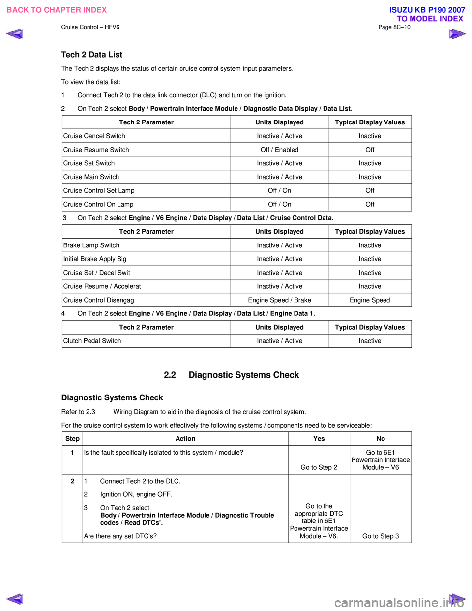
Tech 2 Data List
The Tech 2 displays the status of certain cruise control system input parameters.
To view the data list:
1 Connect Tech 2 to the data link connector (DLC) and turn on the ignition.
2 On Tech 2 select Body / Powertrain Interface Module / Diagnostic Data Display / Data List .
Tech 2 Parameter Units Displayed Typical Display Values
Cruise Cancel Switch Inactive / Active Inactive
Cruise Resume Switch Off / Enabled Off
Cruise Set Switch Inactive / Active Inactive
Cruise Main Switch Inactive / Active Inactive
Cruise Control Set Lamp Off / On Off
Cruise Control On Lamp Off / On Off
3 On Tech 2 select Engine / V6 Engine / Data Display / Data List / Cruise Control Data.
Tech 2 Parameter Units Displayed Typical Display Values
Brake Lamp Switch Inactive / Active Inactive
Initial Brake Apply Sig Inactive / Active Inactive
Cruise Set / Decel Swit Inactive / Active Inactive
Cruise Resume / Accelerat Inactive / Active Inactive
Cruise Control Disengag Engine Speed / Brake Engine Speed
4 On Tech 2 select Engine / V6 Engine / Data Display / Data List / Engine Data 1.
Tech 2 Parameter Units Displayed Typical Display Values
Clutch Pedal Switch Inactive / Active Inactive
2.2 Diagnostic Systems Check
Diagnostic Systems Check
Refer to 2.3 Wiring Diagram to aid in the diagnosis of the cruise control system.
For the cruise control system to work effectively the following systems / components need to be serviceable:
Step Action Yes No
1 Is the fault specifically isolated to this system / module?
Go to Step 2 Go to 6E1
Powertrain Interface Module – V6
2 1 Connect Tech 2 to the DLC.
2 Ignition ON, engine OFF.
3 On Tech 2 select Body / Powertrain Interface Module / Diagnostic Trouble
codes / Read DTCs’.
Are there any set DTC’s? Go to the
appropriate DTC table in 6E1
Powertrain Interface Module – V6. Go to Step 3
BACK TO CHAPTER INDEX TO MODEL INDEXISUZU KB P190 2007
Page 5593 of 6020
Cruise Control – HFV6 Page 8C–15
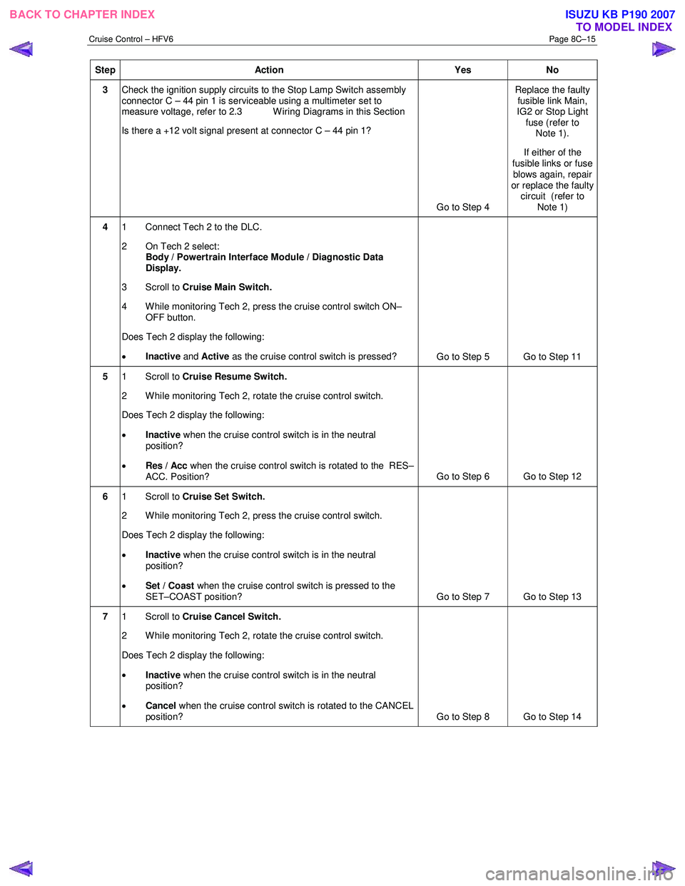
Step Action Yes No
3 Check the ignition supply circuits to the Stop Lamp Switch assembly
connector C – 44 pin 1 is serviceable using a multimeter set to
measure voltage, refer to 2.3 W iring Diagrams in this Section
Is there a +12 volt signal present at connector C – 44 pin 1?
Go to Step 4 Replace the faulty
fusible link Main,
IG2 or Stop Light fuse (refer to Note 1).
If either of the
fusible links or fuse blows again, repair
or replace the faulty circuit (refer to
Note 1)
4 1 Connect Tech 2 to the DLC.
2 On Tech 2 select: Body / Powertrain Interface Module / Diagnostic Data
Display.
3 Scroll to Cruise Main Switch.
4 W hile monitoring Tech 2, press the cruise control switch ON– OFF button.
Does Tech 2 display the following:
• Inactive and Active as the cruise control switch is pressed?
Go to Step 5 Go to Step 11
5 1 Scroll to Cruise Resume Switch.
2 While monitoring Tech 2, rotate the cruise control switch.
Does Tech 2 display the following:
• Inactive when the cruise control switch is in the neutral
position?
• Res / Acc when the cruise control switch is rotated to the RES–
ACC. Position? Go to Step 6 Go to Step 12
6
1 Scroll to Cruise Set Switch.
2 W hile monitoring Tech 2, press the cruise control switch.
Does Tech 2 display the following:
• Inactive when the cruise control switch is in the neutral
position?
• Set / Coast when the cruise control switch is pressed to the
SET–COAST position? Go to Step 7 Go to Step 13
7 1 Scroll to Cruise Cancel Switch.
2 While monitoring Tech 2, rotate the cruise control switch.
Does Tech 2 display the following:
• Inactive when the cruise control switch is in the neutral
position?
• Cancel when the cruise control switch is rotated to the CANCEL
position? Go to Step 8 Go to Step 14
BACK TO CHAPTER INDEX
TO MODEL INDEXISUZU KB P190 2007
Page 5627 of 6020
9-22 ACCESSORIES
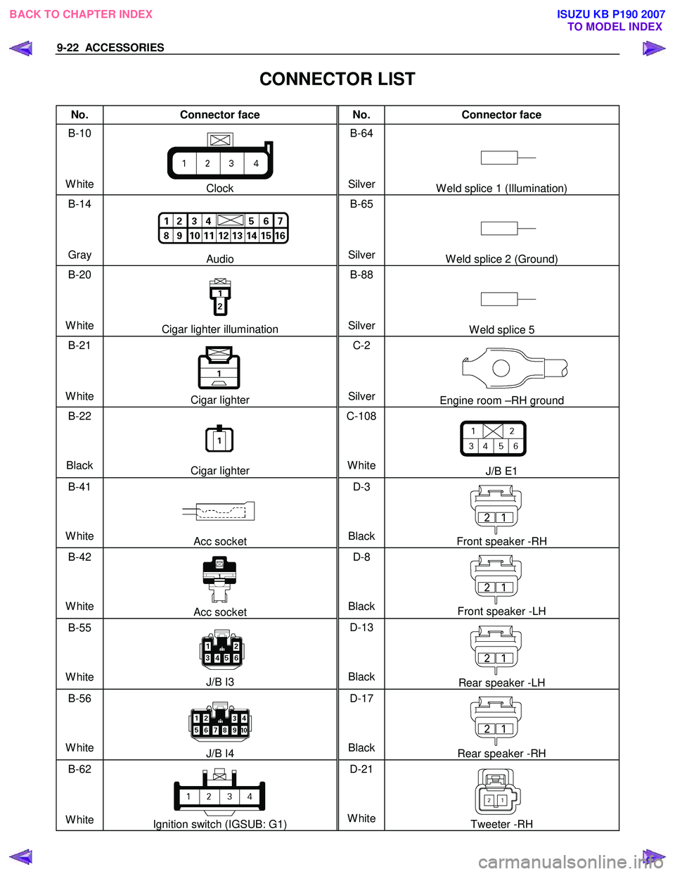
CONNECTOR LIST
No. Connector face No. Connector face
B-10
White
Clock B-64
SilverW eld splice 1 (Illumination)
B-14
Gray
Audio B-65
SilverW eld splice 2 (Ground)
B-20
White
Cigar lighter illumination B-88
SilverW eld splice 5
B-21
White
Cigar lighter C-2
SilverEngine room –RH ground
B-22
Black
Cigar lighter C-108
White
J/B E1
B-41
White
Acc socket D-3
BlackFront speaker -RH
B-42
White
Acc socket D-8
BlackFront speaker -LH
B-55
White
J/B I3 D-13
BlackRear speaker -LH
B-56
White
J/B I4 D-17
BlackRear speaker -RH
B-62
White
Ignition switch (IGSUB: G1) D-21
WhiteTweeter -RH
BACK TO CHAPTER INDEX TO MODEL INDEXISUZU KB P190 2007
Page 5649 of 6020
9A-14 SUPPLEMENTAL RESTRAINT SYSTEM
Component Description
SRS Control Unit
WARNING: DURING SERVICE PROCEDURES, BE
VERY CAREFUL WHEN HANDLING A SRS
CONTROL UNIT. NEVER STRIKE OR JAR THE SRS
CONTORL UNIT. NEVER POWER UP THE SRS
WHEN THE SRS CONTROL UNIT IS NOT RIGIDLY
ATTACHED TO THE VEHICLE. ALL SRS CONTROL
UNIT AND MOUNTING BRACKET FASTENERS
MUST BE CAREFULLY TORQUED AND THE
ARROW MUST BE POINTED TOWARD THE FRONT
OF THE VEHICLE TO ENSURE PROPER
OPERATION OF THE SRS. THE SRS CONTROL
UNIT COULD BE ACTIVATED WHEN POWERED
WHILE NOT RIGIDLY ATTACHED TO THE
VEHICLE WHICH COULD CAUSE DEPLOYMENT
AND RESULT IN PERSONAL INJURY.
The SRS control unit is designed to perform the
following functions in the SRS:
1. Energy Reserve — The SRS control unit maintains 30–Volt Loop Reserve (30VLR) energy supply to
provide deployment energy when ignition voltage is
lost in a frontal crash.
2. Frontal Crash Detection — The SRS control unit monitors vehicle velocity changes to detect frontal
crashes which are severe enough to warrant
deployment.
3. Air Bag Deployment — W hen a frontal crash o
f
sufficient force is detected, the SRS control unit
will cause enough current to flow through the ai
r
bag assembly to deploy the air bag.
4. Malfunction Detection — The SRS control unit performs diagnostic monitoring of SRS electrical
components and sets a diagnostic trouble code
when a malfunction is detected.
5. Frontal Crash Recording — The SRS control unit records information regarding SRS status during
frontal crash.
6. Malfunction Diagnosis — The SRS control unit displays SRS diagnostic trouble codes and system
status information through the use of a scan tool.
7. Driver Notification — The SRS control unit warns the vehicle driver of SRS malfunctions b
y
controlling the “SRS” warning lamp.
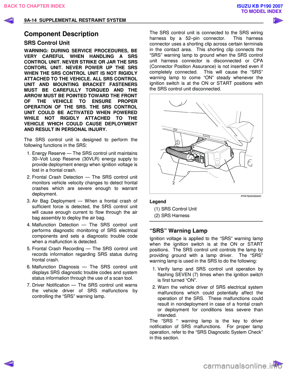
The SRS control unit is connected to the SRS wiring
harness by a 52–pin connector. This harness
connector uses a shorting clip across certain terminals
in the contact area. This shorting clip connects the
“SRS” warning lamp to ground when the SRS control
unit harness connector is disconnected or CP
A
(Connector Position Assurance) is not inserted even i
f
completely connected. This will cause the “SRS”
warning lamp to come “ON” steady whenever the
ignition switch is at the ON or START positions with
the SRS control unit disconnected.
RTW 79ASH000401
Legend
(1) SRS Control Unit
(2) SRS Harness
“SRS” Warning Lamp
Ignition voltage is applied to the “SRS” warning lamp
when the ignition switch is at the ON or START
positions. The SRS control unit controls the lamp b
y
providing ground with a lamp driver. The “SRS”
warning lamp is used in the SRS to do the following:
1. Verify lamp and SRS control unit operation b
y
flashing SEVEN (7) times when the ignition switch
is first turned “ON”.
2. W arn the vehicle driver of SRS electrical system malfunctions which could potentially affect the
operation of the SRS. These malfunctions could
result in nondeployment in case of a frontal crash
or deployment for conditions less severe than
intended.
The “SRS “ warning lamp is the key to drive
r
notification of SRS malfunctions. For proper lamp
operation, refer to the “SRS Diagnostic System Check”
in this section.
BACK TO CHAPTER INDEX TO MODEL INDEXISUZU KB P190 2007
Page 5651 of 6020
9A-16 SUPPLEMENTAL RESTRAINT SYSTEM
RTW 79ASH000201
Seat Belt with Pretensioner (If so
equipped)
The seat belt comprises a seat belt and a cylinder (a
cylinder filled with powder and an ignition device). In
cases of frontal collision which cause a shock
exceeding a specified level, the controller lets current
flow to the inflation circuit. The current ignites the
cylinder of the seat belt, producing gas. The gas helps
tighten the seat belt to restrain firmly the driver’s uppe
r
half in his seat.
RTW 49JSH000201
Steering Column
The steering column absorbs energy and is designed
to compress in a frontal crash to decrease the chance
of injury to the driver.
060R300038
Knee Bolster
The knee bolsters are used to absorb energy to
protect knees and control the forward movement o
f
the vehicle's front seat occupants during a frontal
crash, by limiting leg movement.
Definitions
Air Bag
An inflatable cloth cushion designed to deploy in
certain frontal crashes. It supplements the protection
offered by the seat belts by distributing the impact load
more evenly over the vehicle occupant's head and
torso.
Asynchronous
Performed in a non-periodic fashion, (i.e., no defined
time or interval).
B+
Battery voltage, (B+) The voltage available at the
battery at the time of the indicated measurement.
W ith the key “ON” and the engine not running, the
system voltage will likely be between 12 and 12.5
volts. At idle, the voltage may be 14 to 16 volts. The
voltage could be as low as 10 volts during engine
cranking.
Bulb Check
The SRS control unit will cause the “SRS” warning
lamp to flash seven times and then go “OFF”
whenever the ignition switch transitions to the ON
position from any other ignition switch position and no
malfunctions are detected.
BACK TO CHAPTER INDEX TO MODEL INDEXISUZU KB P190 2007
Page 5652 of 6020
SUPPLEMENTAL RESTRAINT SYSTEM 9A-17
“Continuous Monitoring”
Tests are performed by the SRS control unit on the
SRS every 100 milliseconds while “Ignition 1” voltage
is in the normal operating voltage range at the SRS
control unit.
Data Link Connector (DLC)
Formerly “DLC”, a connector which allows
communication with an external computer, such as a
scan tool.
Datum Line
A base line parallel to the plane of the underbody or
frame from which all vertical measurements originate.
Deploy
To inflate the air bag.
Deployment Loops
The circuits which supply current to the air bag
assemblies to deploy the air bag.
Diagnostic Trouble Code (DTC)
Formerly “Code”, a numerical designator used by the
SRS control unit to indicate specific SRS malfunctions.
Driver Current Source
An output of the SRS control unit which applies current
into the driver air bag assembly circuit during the
“Initiator Assembly Resistance Test”.
Driver Air Bag Assembly
An assembly located in the steering wheel hub
consisting of an inflatable bag, an inflator and an
initiator.
EEPROM
Electrically Erasable Programmable Read Onl
y
Memory. Memory which retains its contents when
power is removed from the SRS control unit.
Ignition Cycle
The voltage at the SRS control unit “Ignition 1” input,
with ignition switch “ON”, is within the normal operating
voltage range for at least ten seconds before turning
the ignition switch “OFF”.
Ignition 1
A battery voltage (B+) circuit which is only powered
when the ignition switch is in the ON, or START
position.
Initiator
The electrical component inside the air bag assembl
y
which, when sufficient current flows, sets off the
chemical reaction that inflates the air bag.
“Initiator Assembly Resistance Test”
Tests are performed once for each ignition cycle when
no malfunctions are detected during “Turn–ON” o
r
“Continuous Monitoring”. This test checks for the
correct SRS control unit configuration for the vehicle,
shorts to “Ignition 1” in the deployment loops, high
resistance or opens in the “Driver Side” and
“Passenger Side” circuits and measures the resistance
of the inflator assembly consisting of 1) Initiators, 2)
SRS coil assembly (driver side only), 3) Connectors
and associated wiring.
Normal Operating Voltage Range
The voltage measured between the SRS control unit
“Ignition 1” terminals and “Ground” terminals is
between 9 and 16 volts.
Passenger Current Source
An output of the SRS control unit which applies current
into the passenger air bag assembly circuit during the
“Initiator Assembly Resistance Test”.
Passenger Air Bag Assembly
An assembly located in the front of the passenger side
of the instrument panel consisting of an inflatable bag,
an inflator and an initiator.
Scan Tool
An external computer used to read diagnostic
information from on–board computers via the data link
connector.
SRS control unit
SRS control unit which provides reserve energy to the
deployment loops, deploys the air bags when required
and performs diagnostic monitoring of all SRS
components.
Serial Data
Information representing the status of the SRS.
SRS
Supplemental Restraint System.
SRS Coil Assembly
An assembly of two current–carrying coils in the drive
r
deployment loop that allows the rotation of the steering
wheel while maintaining the continuous contact of the
driver deployment loop to the driver air bag assembly.
SRS Wiring Harness
The wires and connectors that electrically connect the
components in the SRS.
“Turn–ON”
Test which the SRS control unit performs on the SRS
once during each ignition cycle immediately afte
r
“Ignition 1” voltage is applied to the SRS control unit
and before “Continuous Monitoring”.
BACK TO CHAPTER INDEX TO MODEL INDEXISUZU KB P190 2007
Page 5653 of 6020
9A-18 SUPPLEMENTAL RESTRAINT SYSTEM
Diagnosis
WARNING: TO AVOID DEPLOYMENT WHEN
TROUBLESHOOTING THE SRS, DO NOT USE
ELECTRICAL TEST EQUIPMENT SUCH AS
A
BATTERY–POWERED OR AC–POWERED
VOLTMETER, OHMMETER, ETC., OR ANY TYPE
OF ELECTRICAL EQUIPMENT OTHER THAN THAT
SPECIFIED IN THIS MANUAL. DO NOT USE
A
NON-POWERED PROBE–TYPE TESTER.
INSTRUCTIONS IN THIS MANUAL MUST BE
FOLLOWED CAREFULLY, OTHERWISE
PERSONAL INJURY MAY RESULT.
Diagnostic Trouble Codes
The “SRS Diagnostic System Check” must always be
the starting point of any SRS diagnosis. The “SRS
Diagnostic System Check” checks for proper “SRS”
warning lamp operation and checks for SRS
diagnostic trouble codes using the scan tool.
1. Current diagnostic trouble codes – Malfunctions that are presently being detected. Current
diagnostic trouble codes are stored in RAM
(Random Access Memory).
2. History diagnostic trouble codes – All malfunctions detected since the last time the history memor
y
was cleared. History diagnostic trouble codes are
stored in EEPROM.
Scan Tool Diagnostics
A scan tool is used to read current and history
diagnostic trouble codes and to clear all diagnostic
trouble codes after a repair is completed. The scan
tool must be updated to communicate with the SRS
through a replaceable cartridge before it can be used
for SRS diagnostics. To use the scan tool, connect it
to the data link connector and turn the ignition switch
“ON”. The scan tool reads serial data from the SRS
control unit “Serial Data” line terminal “21” to the data
link connector terminal “2”.
Use Of Special Tools
WARNING: TO AVOID DEPLOYMENT WHEN
TROUBLESHOOTING THE SRS, DO NOT USE
ELECTRICAL TEST EQUIPMENT SUCH AS
A
BATTERY–POWERED OR AC–POWERED
VOLTMETER, OHMMETER, ETC, OR ANY TYPE OF
ELECTRICAL EQUIPMENT OTHER THAN THAT
SPECIFIED IN THIS MANUAL. DO NOT USE
A
NON-POWERED PROBE–TYPE TESTER.
INSTRUCTIONS IN THIS MANUAL MUST BE
FOLLOWED CAREFULLY, OTHERWISE
PERSONAL INJURY MAY RESULT. YOU SHOULD
BE FAMILIAR WITH THE TOOLS LISTED IN THIS
SECTION UNDER THE HANDLING SRS SPECIAL
TOOLS.
You should be able to measure voltage and
resistance. You should be familiar with proper use o
f
a scan tool such as the Tech 2 Diagnostic Computer,
SRS Driver/Passenger Load Tool 5-8840-2421-0,
Connector Test Adapter Kit 5-8840-2835-0 and the
DMM (Digital Multimeter) 5-8840-0366-0.
BACK TO CHAPTER INDEX TO MODEL INDEXISUZU KB P190 2007