Page 5485 of 6020
ELECTRICAL-BODY AND CHASSIS 8A-547
Pin-outs
RUW 580SF000301
No. Pin Function
1 Door ajar switch
2 Door ajar indicator light
3 Tailgate switch
4 Test pin (Internal use only)
5 Key switch remote
6 Ignition switch
7 Battery
8 Hazard battery
9 Unlock
10 Lock
11 Front map light
12 Hazard-RH
13 Hazard-LH
14 Ground
BACK TO CHAPTER INDEX TO MODEL INDEXISUZU KB P190 2007
Page 5486 of 6020

8A-548 ELECTRICAL-BODY AND CHASSIS
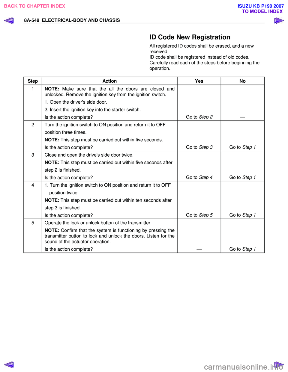
ID Code New Registration
All registered ID codes shall be erased, and a new
received
ID code shall be registered instead of old codes.
Carefully read each of the steps before beginning the
operation.
Step Action Yes No
1 NOTE: Make sure that the all the doors are closed and
unlocked. Remove the ignition key from the ignition switch.
1. Open the driver's side door.
2. Insert the ignition key into the starter switch.
Is the action complete? Go to
Step 2
2 Turn the ignition switch to ON position and return it to OFF
position three times.
NOTE: This step must be carried out within five seconds.
Is the action complete? Go to
Step 3 Go to Step 1
3 Close and open the drive's side door twice.
NOTE: This step must be carried out within five seconds after
step 2 is finished.
Is the action complete? Go to
Step 4 Go to Step 1
4 1. Turn the ignition switch to ON position and return it to OFF
position twice.
NOTE: This step must be carried out within ten seconds after
step 3 is finished.
Is the action complete? Go to
Step 5 Go to Step 1
5 Operate the lock or unlock button of the transmitter.
NOTE: Confirm that the system is functioning by pressing the
transmitter button to lock and unlock the doors. Listen for the
sound of the actuator operation.
Is the action complete?
Go to Step 1
BACK TO CHAPTER INDEX TO MODEL INDEXISUZU KB P190 2007
Page 5488 of 6020

8A-550 ELECTRICAL-BODY AND CHASSIS
ID Code Additional Registration
A new received ID code shall be additionally registered
with holding registered ID codes. W hen a total of
already registered and newly
registered ID code exceeds 4, the oldest one shall be
erased.
Step Action Yes No
1 NOTE: Make sure that the all the doors are closed and
unlocked. Remove the ignition key from the ignition switch.
1. Open the driver's side door.
2. Insert the ignition key into the starter switch.
Is the action complete? Go to
Step 2
2 Turn the ignition switch to ON position and return it to OFF
position three times.
NOTE: This step must be carried out within five seconds .
Is the action complete? Go to
Step 3 Go to Step 1
3 Close and open the driver's side door once.
NOTE: This step must be carried out within five seconds after
step 2 is finished.
Is the action complete? Go to
Step 4 Go to Step 1
4 1. Turn the ignition switch to ON position and return it to OFF
position once.
Check that the hazard lamp blinks 3 times.
NOTE: This step must be carried out within ten seconds after
step 3 is finished.
Is the action complete? Go to
Step 5 Go to Step 1
5 Operate the lock or unlock button of the transmitter.
NOTE: Confirm that the system is functioning by pressing the
transmitter button to lock and unlock the doors. Listen for the
sound of the actuator operation.
Is the action complete?
Go to Step 1
BACK TO CHAPTER INDEX
TO MODEL INDEXISUZU KB P190 2007
Page 5490 of 6020
8A-552 ELECTRICAL-BODY AND CHASSIS
ID Code Check
Numbers of registered ID code shall be checked in this
mode.
Step Action Yes No
1 NOTE: Make sure that the all the doors are closed.
Is the action complete? Go to Step 2
2 Insert the ignition key into the key lock twice, and then re-
inserted.
NOTE: This step must be carried out within five seconds.
Count the number of times the hazard lights flash on and off.
This number is equal to the number of registrations.
Is the action complete? Go to Step 1 Go to Step 1
RUW 59DLF000101
BACK TO CHAPTER INDEX TO MODEL INDEXISUZU KB P190 2007
Page 5519 of 6020

ELECTRICAL-BODY AND CHASSIS 8A-581
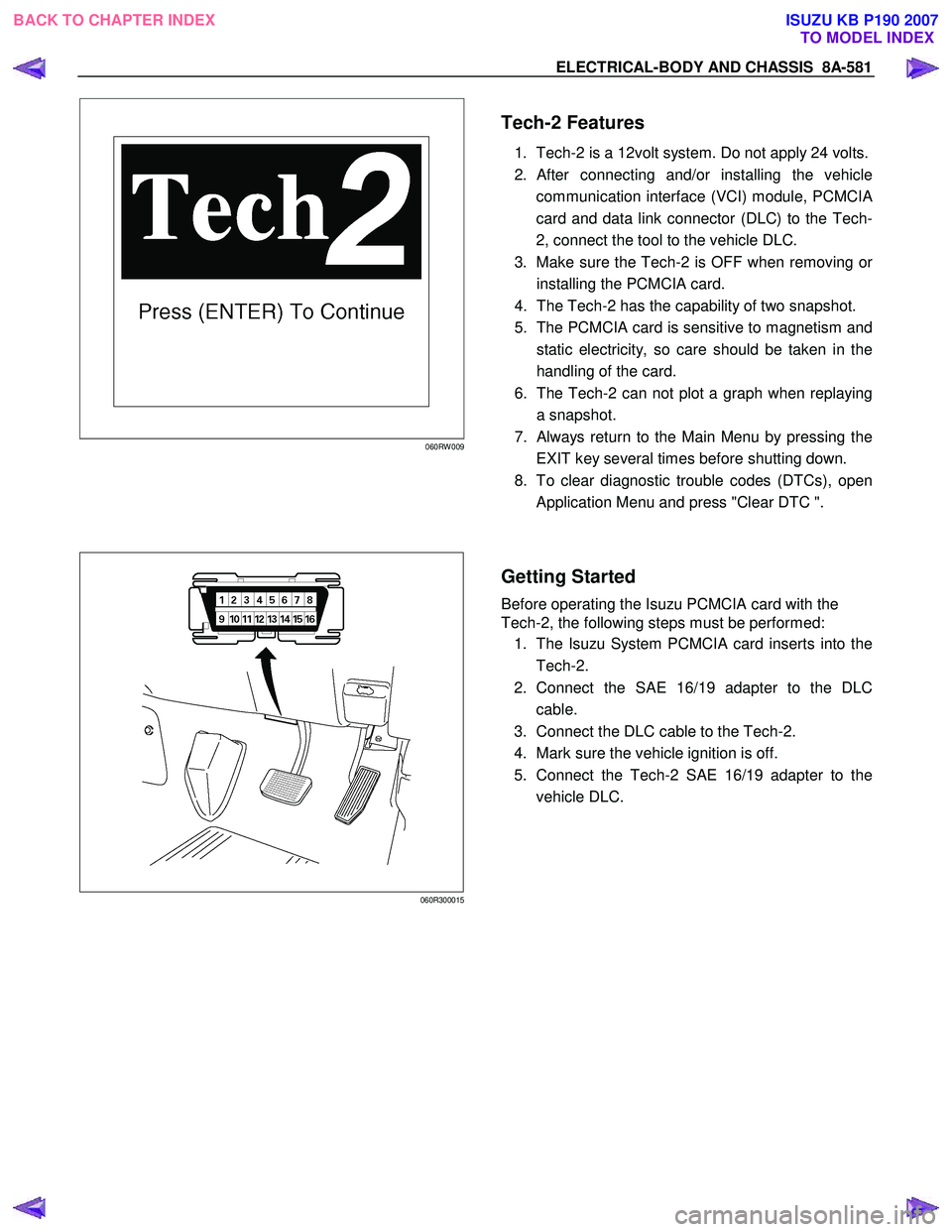
060RW 009
Tech-2 Features
1. Tech-2 is a 12volt system. Do not apply 24 volts.
2.
After connecting and/or installing the vehicle
communication interface (VCI) module, PCMCI
A
card and data link connector (DLC) to the Tech-
2, connect the tool to the vehicle DLC.
3. Make sure the Tech-2 is OFF when removing o
r
installing the PCMCIA card.
4. The Tech-2 has the capability of two snapshot.
5. The PCMCIA card is sensitive to magnetism and
static electricity, so care should be taken in the
handling of the card.
6. The Tech-2 can not plot a graph when replaying
a snapshot.
7.
Always return to the Main Menu by pressing the
EXIT key several times before shutting down.
8. To clear diagnostic trouble codes (DTCs), open
Application Menu and press "Clear DTC ".
060R300015
Getting Started
Before operating the Isuzu PCMCIA card with the
Tech-2, the following steps must be performed:
1. The Isuzu System PCMCIA card inserts into the
Tech-2.
2. Connect the SAE 16/19 adapter to the DLC
cable.
3. Connect the DLC cable to the Tech-2.
4. Mark sure the vehicle ignition is off.
5. Connect the Tech-2 SAE 16/19 adapter to the
vehicle DLC.
BACK TO CHAPTER INDEX TO MODEL INDEXISUZU KB P190 2007
Page 5546 of 6020
8A-608 ELECTRICAL-BODY AND CHASSIS
No. Connector face No. Connector face
B53
White
J/B I1 B63
WhiteIgnition switch (IGSUB: G2)
B54
White
J/B I2 B64
W eld splice 1 (Illumination)
B55
White
J/B I3 B65
W eld splice 2 (Ground)
B56
White
J/B I4 B66
White4W D switch
B57
White
HVAC control unit B67
WhiteCruise main switch
B58
Black
Data link connector B68
WhiteImmobilizer
B59
White
Combination switch-A B69
Gray Door lock switch
B60
Black
Combination switch-B B70
~
B71 NOT USED
B61
Black
Flasher unit B72
YellowInflator module passenger
B62
White
Ignition switch (IGSUB: G1) B73
W eld Splice 3
BACK TO CHAPTER INDEX TO MODEL INDEXISUZU KB P190 2007
Page 5557 of 6020
ELECTRICAL-BODY AND CHASSIS 8A-619
No. Connector face No. Connector face
E1
Gray
Oil pressure switch E9
Gray
T.D.C sensor
E2
(C24SE)
Magnetic clutch E10
SilverEngine ground
E3
Black
Magnetic clutch AC COMP E11
Natural greenNeutral switch
E4
Green
Generator E12
Natural greenNeutral switch
E5
TPS EGR E13
Gray Injector nozzle 1
E6
(C24SE)
Fuel injector (C24SE) E14
Gray
Injector nozzle 2
E6
Injector pump E15
Gray Injector nozzle 3
E7
(C24SE)
Fuel injector (C24SE) E16
Gray
Injector nozzle 4
E8
(C24SE)
Fuel injector (C24SE) E17
Silver
Generator (B)
E9
(C24SE)
Fuel injector (C24SE) E18
(C24SE)
Ignition coil
BACK TO CHAPTER INDEX TO MODEL INDEXISUZU KB P190 2007
Page 5581 of 6020

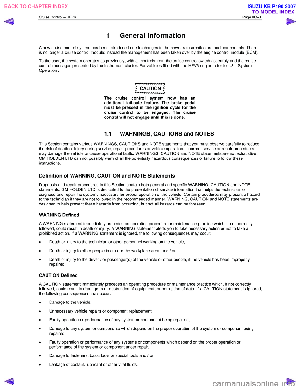
Cruise Control – HFV6 Page 8C–3
1 General Information
A new cruise control system has been introduced due to changes in the powertrain architecture and components. There
is no longer a cruise control module; instead the management has been taken over by the engine control module (ECM).
To the user, the system operates as previously, with all controls from the cruise control switch assembly and the cruise
control messages presented by the instrument cluster. For vehicles fitted with the HFV6 engine refer to 1.3 System
Operation .
The cruise control system now has an
additional fail-safe feature. The brake pedal
must be pressed in the ignition cycle for the
cruise control to be engaged. The cruise
control will not engage until this is done.
1.1 WARNINGS, CAUTIONS and NOTES
This Section contains various W ARNINGS, CAUTIONS and NOTE statements that you must observe carefully to reduce
the risk of death or injury during service, repair procedures or vehicle operation. Incorrect service or repair procedures
may damage the vehicle or cause operational faults. W ARNINGS, CAUTION and NOTE statements are not exhaustive.
GM HOLDEN LTD can not possibly warn of all the potentially hazardous consequences of failure to follow these
instructions.
Definition of WARNING, CAUTION and NOTE Statements
Diagnosis and repair procedures in this Section contain both general and specific W ARNING, CAUTION and NOTE
statements. GM HOLDEN LTD is dedicated to the presentation of service information that helps the technician to
diagnose and repair the systems necessary for proper operation of the vehicle. Certain procedures may present a hazard
to the technician if they are not followed in the recommended manner. W ARNING, CAUTION and NOTE statements are
designed to help prevent these hazards from occurring, but not all hazards can be foreseen.
WARNING Defined
A W ARNING statement immediately precedes an operating procedure or maintenance practice which, if not correctly
followed, could result in death or injury. A WARNING statement alerts you to take necessary action or not to take a
prohibited action. If a W ARNING statement is ignored, the following consequences may occur:
• Death or injury to the technician or other personnel working on the vehicle,
• Death or injury to other people in or near the workplace area, and / or
• Death or injury to the driver / or passenger(s) of the vehicle or other people, if the vehicle has been improperly
repaired.
CAUTION Defined
A CAUTION statement immediately precedes an operating procedure or maintenance practice which, if not correctly
followed, could result in damage to or destruction of equipment, or corruption of data. If a CAUTION statement is ignored,
the following consequences may occur:
• Damage to the vehicle,
• Unnecessary vehicle repairs or component replacement,
• Faulty operation or performance of any system or component being repaired,
• Damage to any system or components which depend on the proper operation of the system or component being
repaired,
• Faulty operation or performance of any systems or components which depend on the proper operation or
performance of the system or component under repair,
• Damage to fasteners, basic tools or special tools and / or
• Leakage of coolant, lubricant or other vital fluids.
BACK TO CHAPTER INDEX
TO MODEL INDEXISUZU KB P190 2007