2007 ISUZU KB P190 Electrical
[x] Cancel search: ElectricalPage 1963 of 6020
6E-346 ENGINE CONTROL SYSTEM (4JK1/4JJ1)
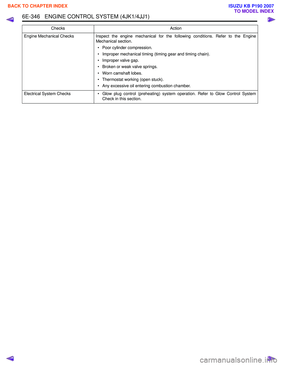
Engine Mechanical ChecksInspect the engine mechanical for the following conditions. Refer to the Engine
Mechanical section.
• Poor cylinder compression.
• Improper mechanical timing (timing gear and timing chain).
• Improper valve gap.
• Broken or weak valve springs.
• Worn camshaft lobes.
• Thermostat working (open stuck).
• Any excessive oil entering combustion chamber.
Electrical System Checks • Glow plug control (preheating) system operation. Refer to Glow Control System
Check in this section.
Checks
Action
BACK TO CHAPTER INDEX
TO MODEL INDEX
ISUZU KB P190 2007
Page 1966 of 6020
ENGINE CONTROL SYSTEM (4JK1/4JJ1) 6E-349
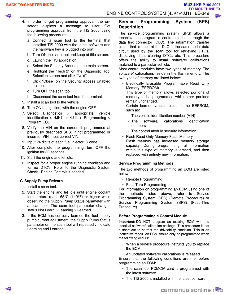
4. In order to get programming approval, the on-screen displays a message to user. Get
programming approval from the TIS 2000 using
the following procedure:
a. Connect a scan tool to the terminal that installed TIS 2000 with the latest software and
the hardware key is plugged into port.
b. Turn ON the scan tool and keep at title screen.
c. Launch the TIS application.
d. Select the Security Access at the main screen.
e. Highlight the “Tech 2” on the Diagnostic Tool Selection screen and click “Next”.
f. Click “Close” on the Security Access Enabled screen.
g. Turn OFF the scan tool.
h. Disconnect the scan tool from the terminal.
5. Install a scan tool to the vehicle.
6. Turn ON the ignition, with the engine OFF.
7. Select Diagnostics > appropriate vehicle identification > 4JK1 or 4JJ1 > Programming >
Program ECU.
8. Verify the VIN on the screen if programmed at previously described SPS. If not programmed or
incorrect VIN, input correct VIN.
9. Input 24 digits of each fuel injector ID code.
10. After complete the programming, turn OFF the ignition for 30 seconds.
11. Start the engine and let idle.
12. Inspect for a proper engine running condition and for no DTC's. Refer to the Diagnostic System
Check - Engine Controls if needed.
G. Supply Pump Relearn 1. Install a scan tool.
2. Start the engine and let idle until engine coolant temperature reads 65 °C (149 °F) or higher while
observing the Supply Pump Status parameter with
a scan tool. The scan tool parameter changes
status Not Learn > Learning > Learned.
3. If the ECM has correctly learned the fuel supply pump current adjustment, the Supply Pump Status
parameter on the scan tool will repeatedly indicate
Learning and Learned.Service Programming System (SPS)
Description
The service programming system (SPS) allows a
technician to program a control module through the
data link connector (DLC). The information transfer
circuit that is used at the DLC is the same serial data
circuit used by the scan tool for retrieving DTCs,
displaying data, clearing DTCs etc. This procedure
offers the ability to install software/ calibrations
matched to a particular vehicle.
Most control modules have two types of memory. The
software/ calibrations reside in the flash memory. The
two types of memory are listed below:
• Electrically Erasable Programmable Read Only Memory (EEPROM)
This type of memory allows selected portions of
memory to be programmed while other portions
remain unchanged.
Certain learned values reside in the EEPROM,
such as:
- The vehicle identification number (VIN)
- The software/ calibrations identification numbers
- The control module security information
• Flash Read Only Memory-Flash Memory Flash memory has increased memory storage
capacity. During programming, all information
within this type of memory is erased, and then
replaced with entirely new information.
Service Programming Methods
The two methods of programming an ECM are listed
below:
• Remote Programming
• Pass Thru Programming
For information on programming an ECM using one of
the methods listed above, refer to Service
Programming System (SPS) (Remote Procedure) or
Service Programming System (SPS) (Pass-Thru
Procedure).
Before Programming a Control Module
Important: DO NOT program an existing ECM with the
identical software/ calibration package. This procedure is not
a short cut to correct the driveability condition. This is an
ineffective repair. An ECM should only be programmed when
the following occurs:
• When a service procedure instructs you to replace the ECM.
• An updated software/ calibrations is released.
Ensure that the following conditions are met before
programming an ECM:
• The scan tool PCMCIA card is programmed with the latest software.
• The TIS 2000 is installed with the latest software.
BACK TO CHAPTER INDEX
TO MODEL INDEX
ISUZU KB P190 2007
Page 1971 of 6020
6E-354 ENGINE CONTROL SYSTEM (4JK1/4JJ1)
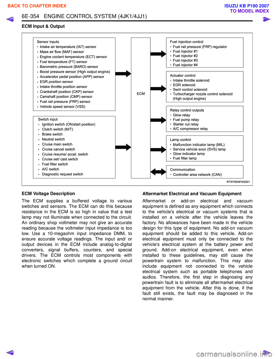
ECM Input & Output
ECM Voltage Description
The ECM supplies a buffered voltage to various
switches and sensors. The ECM can do this because
resistance in the ECM is so high in value that a test
lamp may not illuminate when connected to the circuit.
An ordinary shop voltmeter may not give an accurate
reading because the voltmeter input impedance is too
low. Use a 10-megaohm input impedance DMM, to
ensure accurate voltage readings. The input and/ or
output devices in the ECM include analog-to-digital
converters, signal buffers, counters, and special
drivers. The ECM controls most components with
electronic switches which complete a ground circuit
when turned ON. Aftermarket Electrical and Vacuum Equipment
Aftermarket or add-on electrical and vacuum
equipment is defined as any equipment which connects
to the vehicle's electrical or vacuum systems that is
installed on a vehicle after the vehicle leaves the
factory. No allowances have been made in the vehicle
design for this type of equipment. No add-on vacuum
equipment should be added to this vehicle. Add-on
electrical equipment must only be connected to the
vehicle's electrical system at the battery power and
ground. Add-on electrical equipment, even when
installed to these guidelines, may still cause the
powertrain system to malfunction. This may also
include equipment not connected to the vehicle
electrical system such as portable telephones and
audios. Therefore, the first step in diagnosing any
powertrain fault is to eliminate all aftermarket electrical
equipment from the vehicle. After this is done, if the
fault still exists, the fault may be diagnosed in the
normal manner.
RTW76EMF000501
Sensor inputs
· Intake air temperature (IAT) sensor
· Mass air flow (MAF) sensor
· Engine coolant temperature (ECT) sensor
· Fuel temperature (FT) sensor
· Barometric pressure (BARO) sensor
· Boost pressure sensor (High output engine)
· Accelerator pedal position (APP) sensor
· EGR position sensor
· Intake throttle position sensor
· Crankshaft position (CKP) sensor
· Camshaft position (CMP) sensor
· Fuel rail pressure (FRP) sensor
· Vehicle speed sensor (VSS)
Switch input
· Ignition switch (ON/start position)
· Clutch switch (M/T)
· Brake switch
· Neutral switch
· Cruise main switch
· Cruise cancel switch
· Cruise resume/ accel. switch
· Cruise set/ cast switch
· Fuel filter switch
· A/C switch
· Diagnostic request switch
Fuel injection control
· Fuel rail pressure (FRP) regulator
· Fuel injector #1
· Fuel injector #2
· Fuel injector #3
· Fuel injector #4
Relay control outputs
· Glow relay
· Fuel pump relay
· Starter cut relay
· A/C compressor relay
Lamp control
· Malfunction indicator lamp (MIL)
· Service vehicle soon (SVS) lamp
· Glow indicator lamp
· Fuel filter lamp
Communication
· Controller area network (CAN)
Actuator control
· Intake throttle solenoid
· EGR solenoid
· Swirl control solenoid
· Turbocharger nozzle control solenoid
(High output engine)ECM
BACK TO CHAPTER INDEX
TO MODEL INDEX
ISUZU KB P190 2007
Page 2000 of 6020
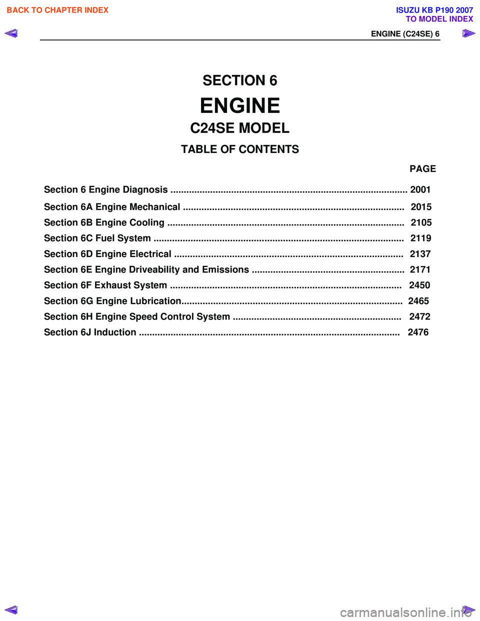
Section 6 Engine Diagnosis .......................................................................................... 2001 PAGE
Section 6A Engine Mechanical .................................................................................... 2015
Section 6B Engine Cooling .......................................................................................... 2105
Section 6C Fuel System .......................................................................... ..................... 2119
Section 6D Engine Electrical ....................................................................................... 2137
Section 6E Engine Driveability and Emissions .......................................................... 2171
Section 6F Exhaust System ........................................................................................ 2450
SECTION 6
ENGINE
TA BLE OF CONTENTS
C24SE MODEL
EN G IN E (C 24SE) 6
Section 6 G En gine L ubri ca tio n.................................................................................... 24 65
Section 6H Engine Speed Control System ................................................................ 2472
Section 6J Induction ................................................................................................... 2476
BACK TO CHAPTER INDEX
TO MODEL INDEX
ISUZU KB P190 2007
Page 2002 of 6020
6-2 ENGINE DIAGNOSIS (C24SE)
Engine Diagnosis
Hard Starting
1.Starting Motor Does Not Turn Over
Trouble Shooting Procedure
Turn on headlights and starter switch.
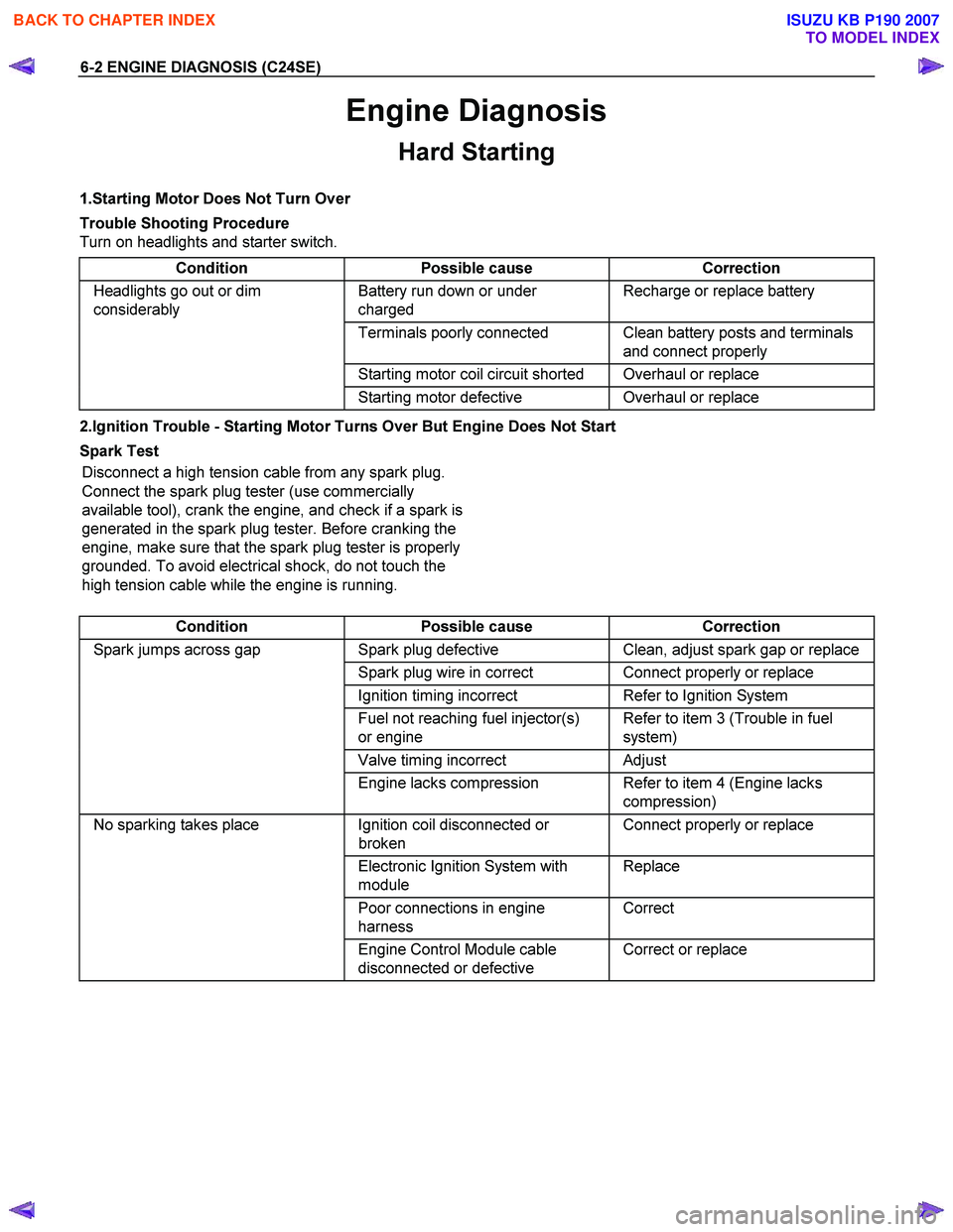
Condition Possible cause Correction
Headlights go out or dim
considerably Battery run down or under
charged Recharge or replace battery
Terminals poorly connected Clean battery posts and terminals
and connect properly
Starting motor coil circuit shorted Overhaul or replace
Starting motor defective Overhaul or replace
2.Ignition Trouble - Starting Motor Turns Over But Engine Does Not Start
Spark Test Disconnect a high tension cable from any spark plug.
Connect the spark plug tester (use commercially
available tool), crank the engine, and check if a spark is
generated in the spark plug tester. Before cranking the
engine, make sure that the spark plug tester is properly
grounded. To avoid electrical shock, do not touch the
high tension cable while the engine is running.
Condition Possible cause Correction
Spark jumps across gap Spark plug defective Clean, adjust spark gap or replace
Spark plug wire in correct Connect properly or replace
Ignition timing incorrect Refer to Ignition System
Fuel not reaching fuel injector(s)
or engine Refer to item 3 (Trouble in fuel
system)
Valve timing incorrect Adjust
Engine lacks compression Refer to item 4 (Engine lacks
compression)
No sparking takes place Ignition coil disconnected or
broken Connect properly or replace
Electronic Ignition System with
module Replace
Poor connections in engine
harness Correct
Engine Control Module cable
disconnected or defective Correct or replace
BACK TO CHAPTER INDEX
TO MODEL INDEX
ISUZU KB P190 2007
Page 2018 of 6020
6A-4 ENGINE MECHANICAL (C24SE)
GENERAL DESCRIPTION
Engine Cleanliness And Care
An automobile engine is a combination of many machined, honed, polished and lapped surfaces with tolerances
that are measured in the thousandths of a millimeter (ten thousandths of an inch). Accordingly, when any internal
engine parts are serviced, care and cleanliness are important. Throughout this section, it should be understood that
proper cleaning and protection of machined surfaces and friction areas is part of the repair procedure. This is
considered standard shop practice even if not specifically stated.
�z A liberal coating of engine oil should be applied to all friction areas during assembly to protect and lubricate
the surfaces on initial operation.
�z W henever valve train components, pistons, piston rings, connecting rods, rod bearings, and crankshaft journal
bearings are removed for service, they should be retained in order.
�z
At the time of installation, they should be installed in the same locations and with the same mating surfaced as
when removed.
�z Battery cables should be disconnected before any major work is performed on the engine. Failure to
disconnect cables may result in damage to wire harness or other electrical parts.
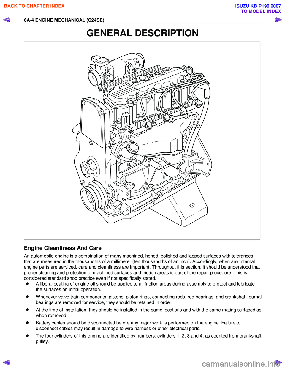
�z The four cylinders of this engine are identified by numbers; cylinders 1, 2, 3 and 4, as counted from crankshaft
pulley.
BACK TO CHAPTER INDEX
TO MODEL INDEX
ISUZU KB P190 2007
Page 2019 of 6020
ENGINE MECHANICAL (C24SE) 6A-5
General Information on Engine Service
The following information on engine service should be noted carefully, as it is important in preventing damage and
contributing to reliable engine performance:
�z W hen raising or supporting the engine for any reason, do not use a jack under the oil pan. Due to the small
clearance between the oil pan and the oil pump strainer, jacking against the oil pan may cause damage to the
oil pick up unit.
�z The 12-volt electrical system is capable of damaging circuits. W hen performing any work where electrical
terminals could possible be grounded, the ground cable of the battery should be disconnected at the battery.
�z Any time the intake air duct or air cleaner is removed, the intake opening should be covered. This will protect
against accidental entrance of foreign material into the cylinder which could cause extensive damage when
the engine is started.
Cylinder Block
The cylinder block is made of cast iron. The crankshaft is supported by five bearings. The bearing cap is made of
nodular cast iron.
Cylinder Head
The cylinder head is made of aluminum alloy casting with a spark plug in the center.
Valve Train
Valve system is a single over head camshaft.
The valves clearance adjustment are hydraulic.
Hydraulic valve lifter adjustment, no adjustment necessary.
Intake Manifold
The intake manifold is made of aluminum alloy.
Exhaust Manifold
The exhaust manifold is made of high Si-Mo nodular iron.
Pistons and Connecting Rods
Aluminum pistons are used after selecting the grade that meets the cylinder bore diameter. Each piston has two
compression rings and one oil ring. The piston pin is made of cast hardened steel. The connecting rod bearings are
made of modular cast iron. The connecting rod bearings are made of steel backed with tri-metal babbitt metal.
Crankshaft and Bearings
The crank shaft is made of modular cast iron. Pins and journal are graded for correct size selection for their bearing.
BACK TO CHAPTER INDEX
TO MODEL INDEX
ISUZU KB P190 2007
Page 2034 of 6020

6A-20 ENGINE MECHANICAL (C24SE)
6. Install power steering pump and V-belt.
Adjust
Adjust power steering pump V-belt tension according to the
corresponding operation.
Installation
7. Install radiator according to the corresponding operation.
8. Install air inlet hose.
9. Install all electrical cable connections, hoses and lines to engine.
10. Install accelerator cable from inlet pipe.
11. Install bonnet.
Inspection
1. Check engine oil level.
2. Fill up cooling system and bleed according to the corresponding operation.
BACK TO CHAPTER INDEX
TO MODEL INDEX
ISUZU KB P190 2007