2007 ISUZU KB P190 Electrical
[x] Cancel search: ElectricalPage 2239 of 6020
ENGINE DRIVEABILITY AND EMISSIONS 6E–69
Reading Diagnostic Trouble Codes Using a
Te c h 2
The procedure for reading diagnostic trouble code(s) is
to used a diagnostic Tech 2. When reading DTC(s),
follow instructions supplied by Tech 2 manufacturer.
Clearing Diagnostic Trouble Codes
To clear Diagnostic Trouble Codes (DTCs), use the
Tech 2 “clear DTCs” or “clear information” function.
When clearing DTCs follow instructions supplied by the
Tech 2 manufacturer.
Diagnosis With Tech 2
If no codes are set:
•Refer to F1: Data Display and identify the electrical
faults that are not indicated by trouble code.
• Refer to “SYMPTOM DIAGNOSIS ”.
If codes are set: 1. Record all trouble codes displayed by Tech 2 and check id the codes are intermittent.
2. Clear the codes.
3. Drive the vehicle for a test to reproduce the faulty status.
4. Check trouble codes again using the Tech 2.
5. If no codes is displayed by test driving, the fault is intermittent. In this case, refer to “DIAGNOSIS
AIDS”.
6. If a code is present, refer to DTC Chart for diagnosis.
7. Check trouble codes again using the Tech 2.
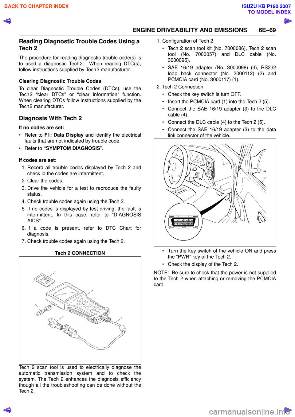
Tech 2 CONNECTION
Tech 2 scan tool is used to electrically diagnose the
automatic transmission system and to check the
system. The Tech 2 enhances the diagnosis efficiency
though all the troubleshooting can be done without the
Te c h 2 . 1. Configuration of Tech 2
• Tech 2 scan tool kit (No. 7000086), Tech 2 scan tool (No. 7000057) and DLC cable (No.
3000095).
• SAE 16/19 adapter (No. 3000098) (3), RS232 loop back connector (No. 3000112) (2) and
PCMCIA card (No. 3000117) (1).
2. Tech 2 Connection
• Check the key switch is turn OFF.
• Insert the PCMCIA card (1) into the Tech 2 (5).
• Connect the SAE 16/19 adapter (3) to the DLC cable (4).
• Connect the DLC cable (4) to the Tech 2 (5).
• Connect the SAE 16/19 adapter (3) to the data link connector of the vehicle.
• Turn the key switch of the vehicle ON and press the “PWR” key of the Tech 2.
• Check the display of the Tech 2.
NOTE: Be sure to check that the power is not supplied
to the Tech 2 when attaching or removing the PCMCIA
card.
BACK TO CHAPTER INDEX
TO MODEL INDEX
ISUZU KB P190 2007
Page 2246 of 6020
6E–76 ENGINE DRIVEABILITY AND EMISSIONS
MISCELLANEOUS TEST
The state of each circuit can be tested by using
miscellaneous test menus. Especially when DTC
cannot be detected, a faulty circuit can be diagnosed by
testing each circuit by means of these menus.
Even DTC has been detected, the circuit tests using
these menus could help discriminate between a
mechanical trouble and an electrical trouble.
Connect Tech 2 and select “Powertrain”, “2.XL L4
HV240” & “Miscellaneous Test”.
F0: Lamps
F0: Malfunction Indicator Lamp
When the Tech 2 is operated, “Malfunction Indicator
Lamp (Check Engine Lamp)” is turned on or off.
The circuit is normal if the “Malfunction Indicator Lamp
(Check Engine Lamp)” in the instrument panel is turned
on or off in accordance with this operation.
F1: Relays
F0: Fuel Pump Relay
When the Tech 2 is operated, fuel pump relay signal
turns ON or OFF.
The circuit is normal if fuel pump sound is generated in
accordance with this operation when key switch is
turned ON.
F1: A/C Clutch Relay
When the Tech 2 is operated, A/C clutch relay signal
turns ON or OFF.
The circuit is normal if A/C compressor clutch is
energized in accordance with this operation when the
engine is running.
F2: EVAP
F0: Purge Solenoid
When the Tech 2 is operated, duty ratio of EVAP purge
solenoid is changed 10%-by-10%.
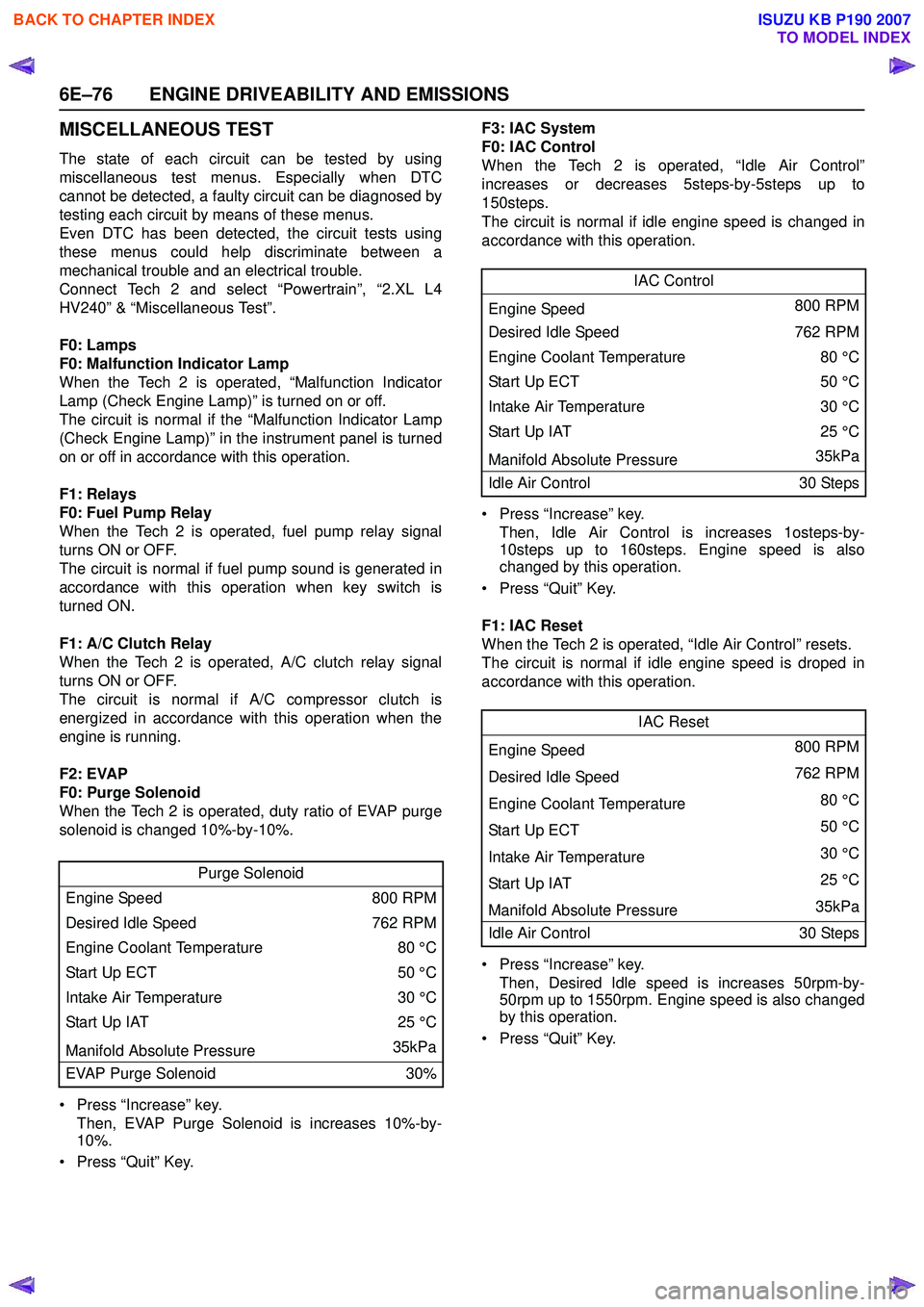
• Press “Increase” key. Then, EVAP Purge Solenoid is increases 10%-by-
10%.
• Press “Quit” Key. F3: IAC System
F0: IAC Control
When the Tech 2 is operated, “Idle Air Control”
increases or decreases 5steps-by-5steps up to
150steps.
The circuit is normal if idle engine speed is changed in
accordance with this operation.
• Press “Increase” key. Then, Idle Air Control is increases 1osteps-by-
10steps up to 160steps. Engine speed is also
changed by this operation.
• Press “Quit” Key.
F1: IAC Reset
When the Tech 2 is operated, “Idle Air Control” resets.
The circuit is normal if idle engine speed is droped in
accordance with this operation.
• Press “Increase” key. Then, Desired Idle speed is increases 50rpm-by-
50rpm up to 1550rpm. Engine speed is also changed
by this operation.
• Press “Quit” Key.
Purge Solenoid
Engine Speed 800 RPM
Desired Idle Speed 762 RPM
Engine Coolant Temperature 80 °C
Start Up ECT 50 °C
Intake Air Temperature 30 °C
Start Up IAT 25 °C
Manifold Absolute Pressure 35kPa
EVAP Purge Solenoid 30%
IAC Control
Engine Speed 800 RPM
Desired Idle Speed 762 RPM
Engine Coolant Temperature 80 °C
Sta rt U p E C T 50 °C
Intake Air Temperature 30 °C
Start Up IAT25 °C
Manifold Absolute Pressure 35kPa
Idle Air Control 30 Steps
IAC Reset
Engine Speed 800 RPM
Desired Idle Speed 762 RPM
Engine Coolant Temperature 80 °C
Sta rt U p E C T 50 °C
Intake Air Temperature 30 °C
Start Up IAT 25 °C
Manifold Absolute Pressure 35kPa
Idle Air Control 30 Steps
BACK TO CHAPTER INDEX
TO MODEL INDEX
ISUZU KB P190 2007
Page 2254 of 6020
6E–84 ENGINE DRIVEABILITY AND EMISSIONS
SERVICE PROGRAMMING SYSTEM (SPS)
The procedure to program the control unit by using the
Service Programming System (SPS) software contained
in TIS2000 is explained below.
NOTE:
• If the Engine Control Module (ECM) was programmed, the Immobilizer System must be
linked to the ECM: Refer to section 11
“Immobilizer System-ECM replacement” for the
ECM/Immobilizer linking procedure.
• Should Tech2 display "SPS Procedure was not successful", engine will not start, but no DTCs
are present, low battery voltage or poor electrical
connections should be the primary suspects.
Perform the SPS procedure again after rectifying
the fault/s. IMPORTANT:
Perform the following checks before attempting to
program the control unit:
• The Tech2 PCMCIA card is programmed with The latest software release.
• The latest release of TIS2000 is loaded on the PC.
• The vehicle battery is fully charged.
• The control unit to be programmed is connected to the vehicle.
1. Preparations of TIS 2000 1. Connect Tech 2 to P/C.
2. Check to see if Hardware Key is plugged into Port.
3. Activate TIS 2000 by P/C.
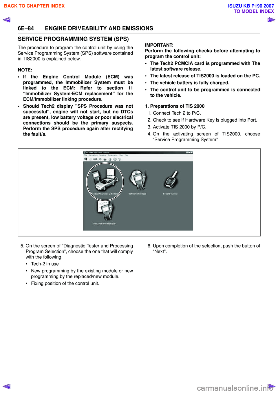
4. On the activating screen of TIS2000, choose “Service Programming System”
5. On the screen of “Diagnostic Tester and Processing Program Selection”, choose the one that will comply
with the following.
• Tech-2 in use
• New programming by the existing module or new programming by the replaced/new module.
• Fixing position of the control unit. 6. Upon completion of the selection, push the button of
“Next”.
BACK TO CHAPTER INDEX
TO MODEL INDEX
ISUZU KB P190 2007
Page 2259 of 6020
ENGINE DRIVEABILITY AND EMISSIONS 6E–89
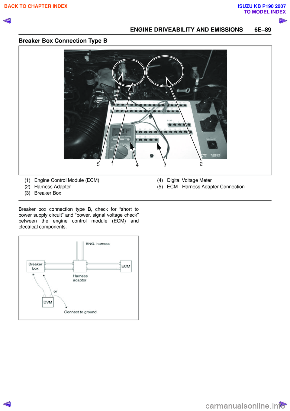
Breaker Box Connection Type B
Breaker box connection type B, check for “short to
power supply circuit” and “power, signal voltage check”
between the engine control module (ECM) and
electrical components.
5 1
4 3 2
(1) Engine Control Module (ECM)
(2) Harness Adapter
(3) Breaker Box (4) Digital Voltage Meter
(5) ECM - Harness Adapter Connection
BACK TO CHAPTER INDEX
TO MODEL INDEX
ISUZU KB P190 2007
Page 2260 of 6020
6E–90 ENGINE DRIVEABILITY AND EMISSIONS
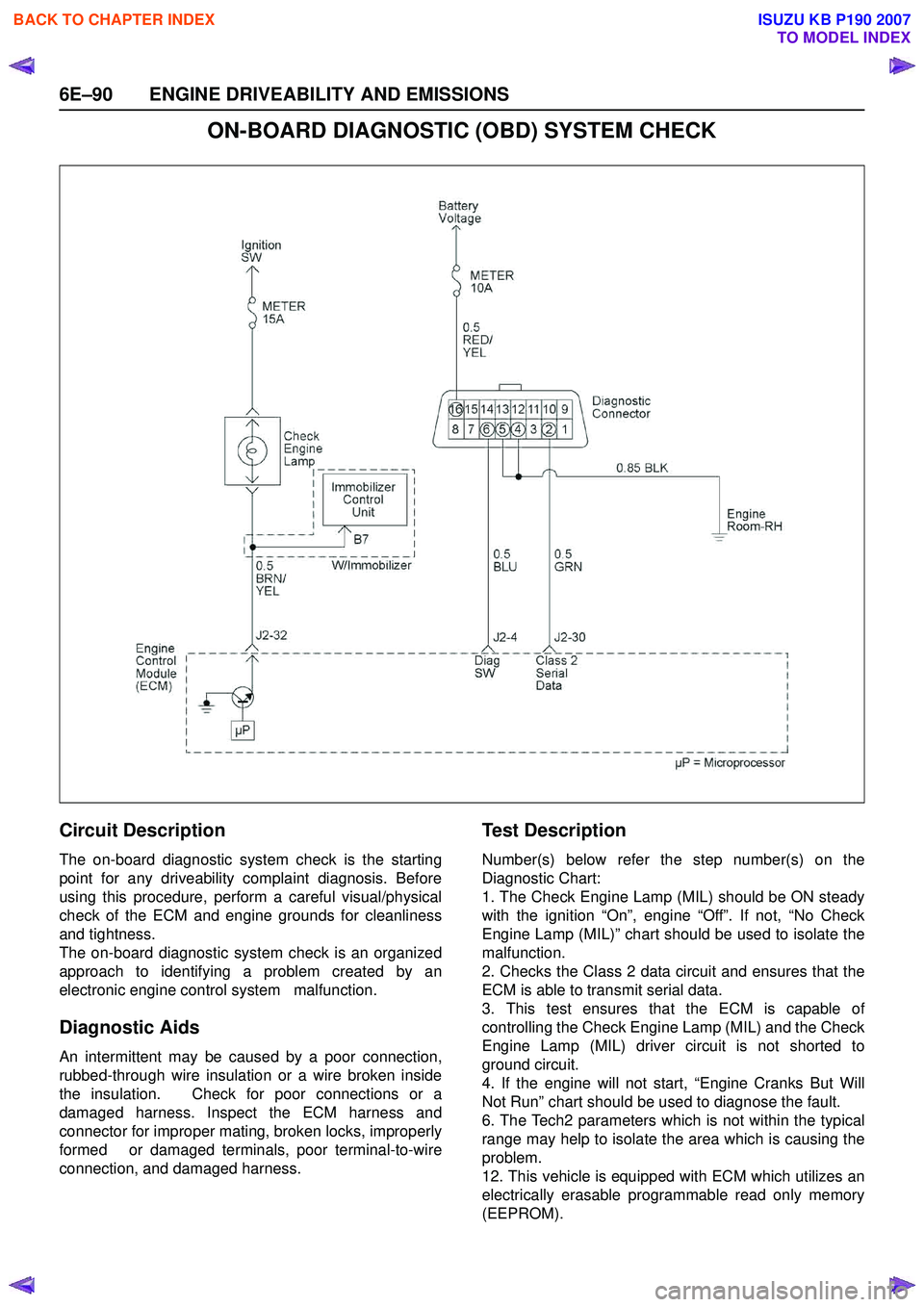
ON-BOARD DIAGNOSTIC (OBD) SYSTEM CHECK
Circuit Description
The on-board diagnostic system check is the starting
point for any driveability complaint diagnosis. Before
using this procedure, perform a careful visual/physical
check of the ECM and engine grounds for cleanliness
and tightness.
The on-board diagnostic system check is an organized
approach to identifying a problem created by an
electronic engine control system malfunction.
Diagnostic Aids
An intermittent may be caused by a poor connection,
rubbed-through wire insulation or a wire broken inside
the insulation. Check for poor connections or a
damaged harness. Inspect the ECM harness and
connector for improper mating, broken locks, improperly
formed or damaged terminals, poor terminal-to-wire
connection, and damaged harness.
Te s t D e s c r i p t i o n
Number(s) below refer the step number(s) on the
Diagnostic Chart:
1. The Check Engine Lamp (MIL) should be ON steady
with the ignition “On”, engine “Off”. If not, “No Check
Engine Lamp (MIL)” chart should be used to isolate the
malfunction.
2. Checks the Class 2 data circuit and ensures that the
ECM is able to transmit serial data.
3. This test ensures that the ECM is capable of
controlling the Check Engine Lamp (MIL) and the Check
Engine Lamp (MIL) driver circuit is not shorted to
ground circuit.
4. If the engine will not start, “Engine Cranks But Will
Not Run” chart should be used to diagnose the fault.
6. The Tech2 parameters which is not within the typical
range may help to isolate the area which is causing the
problem.
12. This vehicle is equipped with ECM which utilizes an
electrically erasable programmable read only memory
(EEPROM).
BACK TO CHAPTER INDEX
TO MODEL INDEX
ISUZU KB P190 2007
Page 2268 of 6020
6E–98 ENGINE DRIVEABILITY AND EMISSIONS
FUEL METERING SYSTEM CHECK
Some failures of the fuel metering system will result in
an “Engine Cranks But Will Not Run” symptom. If this
condition exists, refer to the Cranks But Will Not Run
chart. This chart will determine if the problem is caused
by the ignition system, the ECM, or the fuel pump
electrical circuit.
Refer to Fuel System Electrical Test for the fuel system
wiring schematic.
If there is a fuel delivery problem, refer to Fuel System
Diagnosis , which diagnoses the fuel injectors, the fuel
pressure regulator, and the fuel pump.
Followings are applicable to the vehicles with
closed Loop System:
If a malfunction occurs in the fuel metering system, it
usually results in either a rich HO2S signal or a lean
HO2S signal. This condition is indicated by the HO2S
voltage, which causes the ECM to change the fuel
calculation (fuel injector pulse width) based on the
HO2S reading. Changes made to the fuel calculation
will be indicated by a change in the long term fuel trim
values which can be monitored with a Scan Tool. Ideal
long term fuel trim values are around 0%; for a lean
HO2S signal, the ECM will add fuel, resulting in a fuel
trim value above 0%. Some variations in fuel trim values
are normal because all engines are not exactly the
same. If the evaporative emission canister purge is 02
status may be rich condition. 02 status indicates the
lean condition, refer to DTC P1171 for items which can
cause a lean HO2S signal.
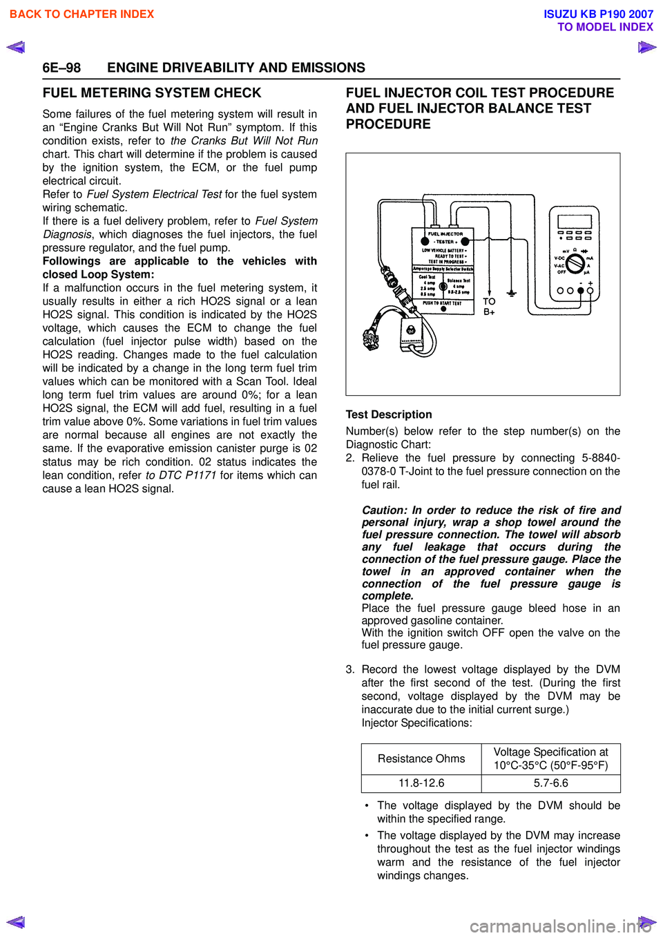
FUEL INJECTOR COIL TEST PROCEDURE
AND FUEL INJECTOR BALANCE TEST
PROCEDURE
Test Description
Number(s) below refer to the step number(s) on the
Diagnostic Chart:
2. Relieve the fuel pressure by connecting 5-8840- 0378-0 T-Joint to the fuel pressure connection on the
fuel rail.
Caution: In order to reduce the risk of fire and
personal injury, wrap a shop towel around the
fuel pressure connection. The towel will absorb
any fuel leakage that occurs during the
connection of the fuel pressure gauge. Place the
towel in an approved container when the
connection of the fuel pressure gauge is
complete.
Place the fuel pressure gauge bleed hose in an
approved gasoline container.
With the ignition switch OFF open the valve on the
fuel pressure gauge.
3. Record the lowest voltage displayed by the DVM after the first second of the test. (During the first
second, voltage displayed by the DVM may be
inaccurate due to the initial current surge.)
Injector Specifications:
• The voltage displayed by the DVM should be within the specified range.
• The voltage displayed by the DVM may increase throughout the test as the fuel injector windings
warm and the resistance of the fuel injector
windings changes. Resistance Ohms
Voltage Specification at
10°C-35°C (50°F-95°F)
11.8-12.6 5.7-6.6
BACK TO CHAPTER INDEX
TO MODEL INDEX
ISUZU KB P190 2007
Page 2273 of 6020
ENGINE DRIVEABILITY AND EMISSIONS 6E–103
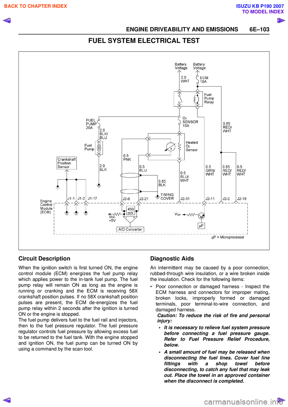
FUEL SYSTEM ELECTRICAL TEST
Circuit Description
When the ignition switch is first turned ON, the engine
control module (ECM) energizes the fuel pump relay
which applies power to the in-tank fuel pump. The fuel
pump relay will remain ON as long as the engine is
running or cranking and the ECM is receiving 58X
crankshaft position pulses. If no 58X crankshaft position
pulses are present, the ECM de-energizes the fuel
pump relay within 2 seconds after the ignition is turned
ON or the engine is stopped.
The fuel pump delivers fuel to the fuel rail and injectors,
then to the fuel pressure regulator. The fuel pressure
regulator controls fuel pressure by allowing excess fuel
to be returned to the fuel tank. With the engine stopped
and ignition ON, the fuel pump can be turned ON by
using a command by the scan tool.
Diagnostic Aids
An intermittent may be caused by a poor connection,
rubbed-through wire insulation, or a wire broken inside
the insulation. Check for the following items:
• Poor connection or damaged harness - Inspect the ECM harness and connectors for improper mating,
broken locks, improperly formed or damaged
terminals, poor terminal-to-wire connection, and
damaged harness. Caution: To reduce the risk of fire and personal
injury:
• It is necessary to relieve fuel system pressure before connecting a fuel pressure gauge.
Refer to Fuel Pressure Relief Procedure,
below.
• A small amount of fuel may be released when disconnecting the fuel lines. Cover fuel line
fittings with a shop towel before
disconnecting, to catch any fuel that may leak
out. Place the towel in an approved container
when the disconnect is completed.
BACK TO CHAPTER INDEX
TO MODEL INDEX
ISUZU KB P190 2007
Page 2274 of 6020
6E–104 ENGINE DRIVEABILITY AND EMISSIONS
Fuel Pressure Relief Procedure
1. Remove the fuel cap.
2. Remove the fuel pump relay from the underhood relay center.
3. Start the engine and alow it to stall.
4. Crank the engine for an additional 3 seconds.
Fuel Pressure Gauge Installation
1. Remove the fuel pressure fitting cap.
2. Install fuel pressure gauge 5-8840-0378-0 to the fuel feed line located in front of and above the right
side valve cover.
3. Reinstall the fuel pump relay.
Fuel System Electrical Test
Step Action Value(s) Yes No
1 Was the “On-Board Diagnostic (OBD) System Check” performed?
—Go to Step 2Go to
On Board
Diagnostic
(OBD) System Check
2 1. Using the Tech 2, ignition “On” and engine “On”. 2. Select the “Miscellaneous Test” and perform the“Fuel Pump Relay” in the “Relays”.
3. Operate the Tech 2 in accordance with procedure.
Was the fuel pump operated, when the Tech 2 is
operated? —Go to
Fuel
System
Diagnosis Go to Step 3
3 Check the “Fuel Pump” fuse (20A). If the fuse is burnt out, repair as necessary.
Was the problem found? — Verify repair Go to Step 4
4 Check for poor/faulty connection at the fuel pump, fuel pump relay or ECM connector. If a poor/faulty
connection is found, repair as necessary.
Was the problem found?
— Verify repair Go to Step 5
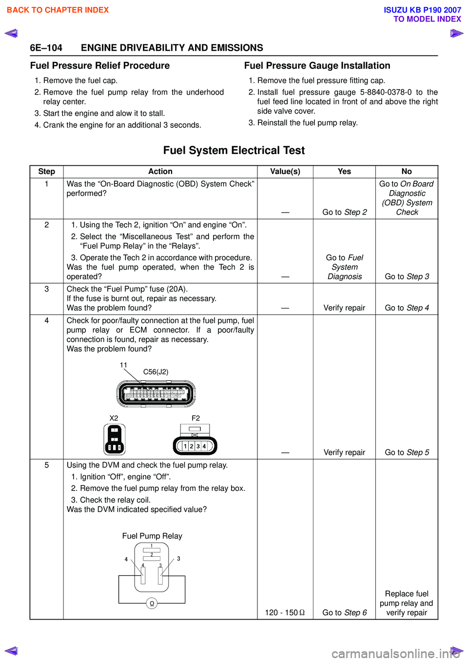
5 Using the DVM and check the fuel pump relay. 1. Ignition “Off”, engine “Off”.
2. Remove the fuel pump relay from the relay box.
3. Check the relay coil.
Was the DVM indicated specified value?
120 - 150ΩGo to Step 6 Replace fuel
pump relay and verify repair
11C56(J2)
F2
X2
Fuel Pump Relay
3
4 2
1
Ω
34
BACK TO CHAPTER INDEX
TO MODEL INDEX
ISUZU KB P190 2007