2007 ISUZU KB P190 Electrical
[x] Cancel search: ElectricalPage 2143 of 6020
6D1-6 ENGINE ELECTRICAL
1
5
3
4 2
Removal
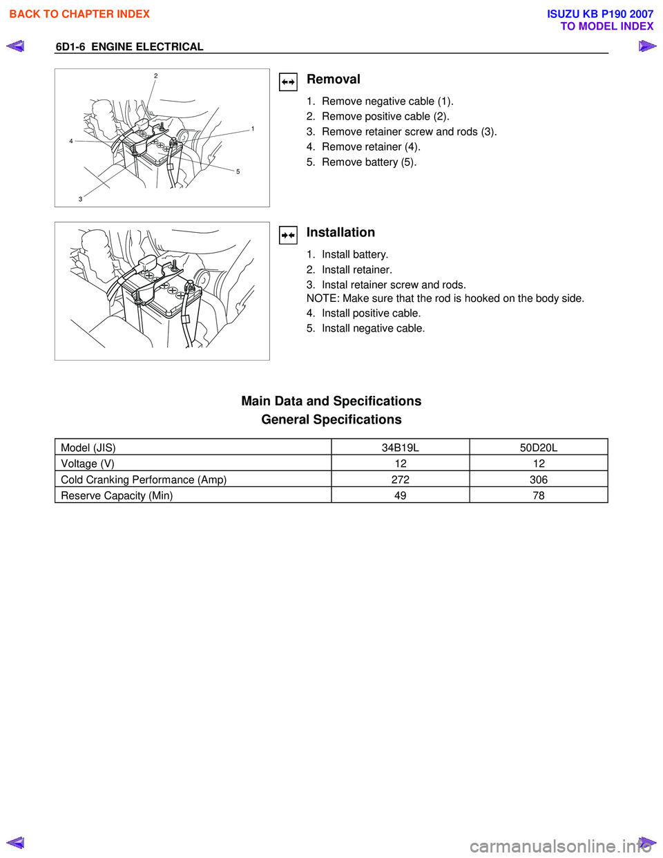
1. Remove negative cable (1).
2. Remove positive cable (2).
3. Remove retainer screw and rods (3).
4. Remove retainer (4).
5. Remove battery (5).
Installation
1. Install battery.
2. Install retainer.
3. Instal retainer screw and rods.
NOTE: Make sure that the rod is hooked on the body side.
4. Install positive cable.
5. Install negative cable.
Main Data and Specifications General Specifications
Model (JIS) 34B19L 50D20L
Voltage (V) 12 12
Cold Cranking Performance (Amp) 272 306
Reserve Capacity (Min) 49 78
BACK TO CHAPTER INDEX
TO MODEL INDEX
ISUZU KB P190 2007
Page 2146 of 6020
IGNITION SYSTEM 6D2-3
Spark Plug
Removal
1. Remove spark plugs.
Inspection and Repair
The spark plug affects entire engine performance and
therefore its inspection is very important.
• Check electrode and insulator for presence of cracks, and
replace if any.
• Check electrode for wear, and replace if necessary.
• Check gasket for damage, and replace if necessary.
• Measure insulation resistance with an ohmmeter, and
replace if faulty.
• Adjust spark plug gap to 1.0 - 1.1 mm (0.027 in) - 0.8 mm
(0.031 in).
• Check fuel and electrical systems if spark plug is extremely
dirty.
• Use spark plugs having low heat value (hot type plug) if fuel
and electrical systems are normal.
• Use spark plugs having high heat value (cold type plug) i
f
insulator and electrode are extremely burned.
Sooty Spark Plugs
Much deposit of carbon or oil on the electrode and insulator of
spark plug reduces the engine performance.
Possible causes:
• Too rich mixture
• Presence of oil in combustion chamber
• Incorrectly adjusted spark plug gap
Burning Electrodes
This fault is characterized by scorched or heavily oxidized
electrode or blistered insulator nose.
Possible causes:
• Too lean mixture
• Improper heat value
Measuring Insulation Resistance
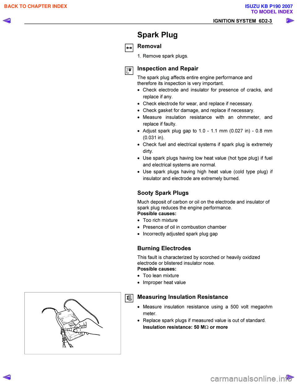
• Measure insulation resistance using a 500 volt megaohm
meter.
• Replace spark plugs if measured value is out of standard.
Insulation resistance: 50 M Ω or more
BACK TO CHAPTER INDEX
TO MODEL INDEX
ISUZU KB P190 2007
Page 2159 of 6020
STARTING AND CHARGING SYSTEM 6D3-11
Warning
Do not reverse S and L connections as this will destroy the
warning lamp circuit of the regulator.
Ensure good electrical contact beween generator earth and
battery negative,
Operation
W ith the Iginiton switch turnded "ON", current is supplied via
the warning lamp to the "L" terminal of the regulator. Base
current is fed to T15 causing it to turn on, current then flows
from B+ through the rotor winding via the regulator brushes
and the collector emitter junction of T15 to earth completing
the circuit. The current in the rotor causes a magnetic field
between adjacent poles to be created, this field is rotated and
cuts the windings of the stator at right angles inducing a
voltage into them.
As the speed is increased this induced voltage increases and
results in curent being rectified in the 3 phase diode bridge and
supplied as DC to the B+ output and hence to the battery.
W hen the voltage at the B+ terminal of the battery reaches
around 14.2 volts, this voltage is monitored by the "S" lead and
turns the regulator Hybrid base current to T15 OFF removing
rotor current, resulting in a decrease in output voltage to below
the regulating voltage, T15 base current turns ON and the
whole cycle is repeated very rapidly.
D38 protects T15 and the regulator against the back voltage
developed across the rotor winding when T15 turns OFF.
The new generated EP regulators incorporate current limiting
in the warning lamp circuit.
Backup Regulation
The EP regulator will limit the output voltage to a safe level
should either the main B+ cable or the battery sense wire
become decoupled, the output voltage will be slightly above the
normal setting(1-3 volts).
Start up phase
W hen the Iginition switch is turned on and the engine is not
running, the current to the rotor is reduced by switching it on
and off at a 50% duty cycle, the frequency is approximately 4
KHz and may be audible at times.
This is quite normal, once the engine is started normal
regulation commences.
Warning lamp failure
Should the warning lamp fail, the generator will self excite by
deriving a small current from the phase connecion allowing the
voltage to build up to regulating level.
Note: no filed current will flow when the engine is cranking.
BACK TO CHAPTER INDEX
TO MODEL INDEX
ISUZU KB P190 2007
Page 2168 of 6020
6D3-20 STARTING AND CHARGING SYSTEM
Load regulation test
Increase the engine speed until the generator is running at
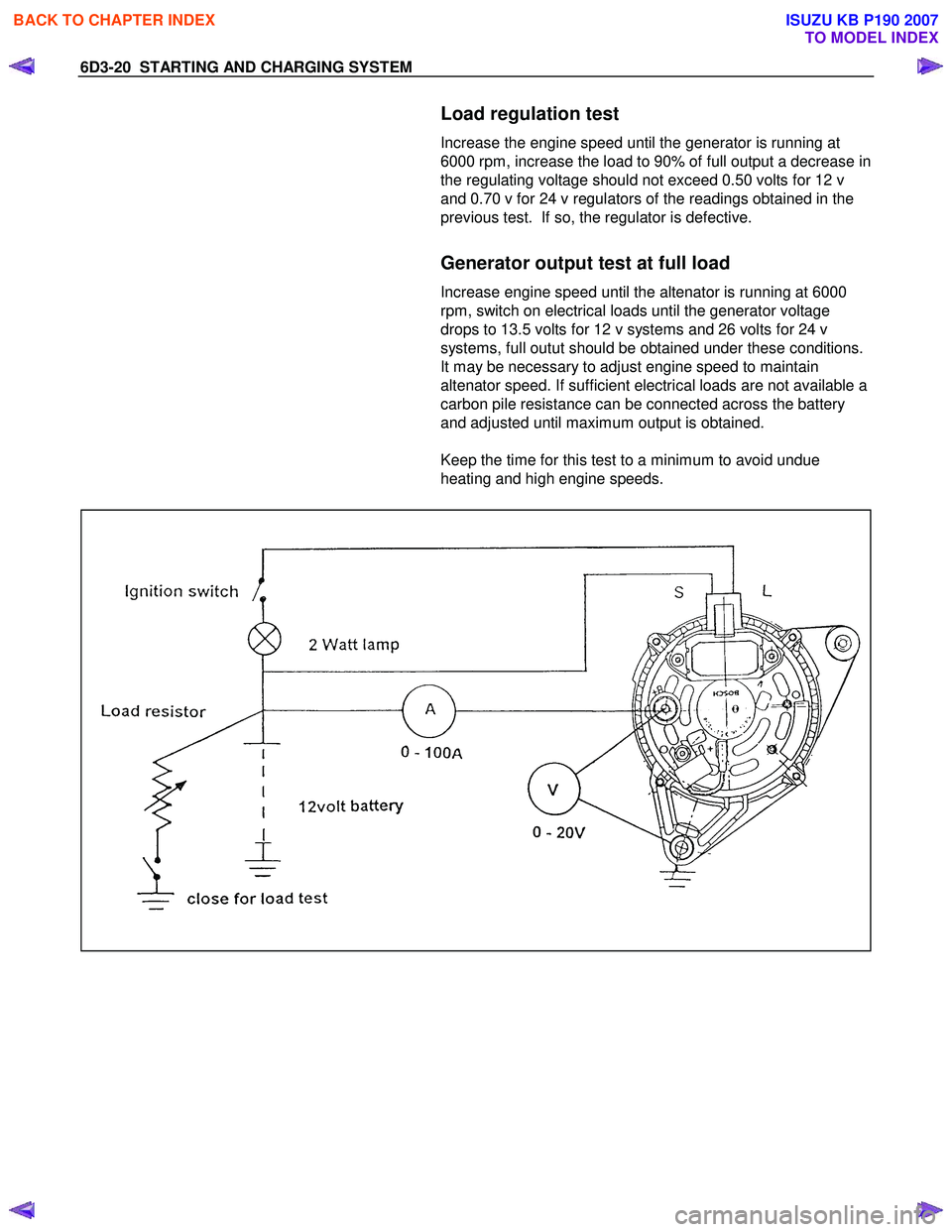
6000 rpm, increase the load to 90% of full output a decrease in
the regulating voltage should not exceed 0.50 volts for 12 v
and 0.70 v for 24 v regulators of the readings obtained in the
previous test. If so, the regulator is defective.
Generator output test at full load
Increase engine speed until the altenator is running at 6000
rpm, switch on electrical loads until the generator voltage
drops to 13.5 volts for 12 v systems and 26 volts for 24 v
systems, full outut should be obtained under these conditions.
It may be necessary to adjust engine speed to maintain
altenator speed. If sufficient electrical loads are not available a
carbon pile resistance can be connected across the battery
and adjusted until maximum output is obtained.
Keep the time for this test to a minimum to avoid undue
heating and high engine speeds.
BACK TO CHAPTER INDEX
TO MODEL INDEX
ISUZU KB P190 2007
Page 2171 of 6020
SECTION 6E
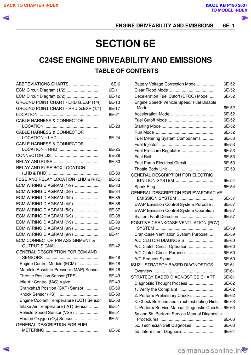
TABLE OF CONTENTS
C24SE ENGINE DRIVEABILITY AND EMISSIONS
ABBREVIATIONS CHARTS ......................... 6E-6
ECM Circuit Diagram (1/2) ............................ 6E-11
ECM Circuit Diagram (2/2) ............................ 6E-12
GROUND POINT CHART - LHD G.EXP (1/4) 6E-13
GROUND POINT CHART - RHD G.EXP (1/4) 6E-17
LOCATION ................................................... 6E-21
CABLE HARNESS & CONNECTOR LOCATION .............................................. 6E-23
CABLE HARNESS & CONNECTOR LOCATION - LHD ................................... 6E-24
CABLE HARNESS & CONNECTOR LOCATION - RHD ................................... 6E-25
CONNECTOR LIST ...................................... 6E-28
RELAY AND FUSE ....................................... 6E-30
RELAY AND FUSE BOX LOCATION (LHD & RHD) ........................................... 6E-30
FUSE AND RELAY LOCATION (LHD & RHD) 6E-32
ECM WIRING DIAGRAM (1/9) ..................... 6E-33
ECM WIRING DIAGRAM (2/9) ..................... 6E-34
ECM WIRING DIAGRAM (3/9) ..................... 6E-35
ECM WIRING DIAGRAM (4/9) ..................... 6E-36
ECM WIRING DIAGRAM (5/9) ..................... 6E-37
ECM WIRING DIAGRAM (6/9) ..................... 6E-38
ECM WIRING DIAGRAM (7/9) ..................... 6E-39
ECM WIRING DIAGRAM (8/9) ..................... 6E-40
ECM WIRING DIAGRAM (9/9) ..................... 6E-41
ECM CONNECTOR PIN ASSIGNMENT & OUTPUT SIGNAL .................................... 6E-42
GENERAL DESCRIPTION FOR ECM AND SENSORS ............................................... 6E-48
Engine Control Module (ECM) ................... 6E-48
Manifold Absolute Pressure (MAP) Sensor 6E-48
Throttle Position Sensor (TPS) .................. 6E-49
Idle Air Control (IAC) Valve ....................... 6E-49
Crankshaft Position (CKP) Sensor ............ 6E-50
Knock Sensor (KS) .................................... 6E-50
Engine Coolant Temperature (ECT) Sensor 6E-50
Intake Air Temperature (IAT) Sensor ........ 6E-51
Vehicle Speed Sensor (VSS) .................... 6E-51
Heated Oxygen (O
2) Sensor ..................... 6E-51
GENERAL DESCRIPTION FOR FUEL METERING .............................................. 6E-52 Battery Voltage Correction Mode ............... 6E-52
Clear Flood Mode ...................................... 6E-52
Deceleration Fuel Cutoff (DFCO) Mode .... 6E-52
Engine Speed/ Vehicle Speed/ Fuel Disable Mode ........................................................ 6E-52
Acceleration Mode ..................................... 6E-52
Fuel Cutoff Mode ....................................... 6E-52
Starting Mode ............................................ 6E-52
Run Mode .................................................. 6E-52
Fuel Metering System Components .......... 6E-53
Fuel Injector ............................................... 6E-53
Fuel Pressure Regulator ............................ 6E-53
Fuel Rail ..................................................... 6E-53
Fuel Pump Electrical Circuit ....................... 6E-53
Thottle Body Unit ....................................... 6E-53
GENERAL DESCRIPTION FOR ELECTRIC IGNITION SYSTEM ................................. 6E-54
Spark Plug ................................................. 6E-54
GENERAL DESCRIPTION FOR EVAPORATIVE EMISSION SYSTEM ............................... 6E-57
EVAP Emission Control System Purpose .. 6E-57
EVAP Emission Control System Operation 6E-57
System Fault Detection .............................. 6E-57
POSITIVE CRANKCASE VENTILATION (PCV) SYSTEM .................................................. 6E-59
Crankcase Ventilation System Purpose .... 6E-59
A/C CLUTCH DIAGNOSIS ........................ 6E-60
A/C Clutch Circuit Operation ...................... 6E-60
A/C Clutch Circuit Purpose ........................ 6E-60
A/C Request Signal ................................... 6E-60
ISUZU STRATEGY BASED DIAGNOSTICS 6E-61
Overview .................................................... 6E-61
STRATEGY BASED DIAGNOSTICS CHART 6E-61 Diagnostic Thought Process ...................... 6E-62
1. Verify the Complaint .............................. 6E-62
2. Perform Preliminary Checks .................. 6E-62
3. Check Bulletins and Troubleshooting Hints 6E-63
4. Perform Service Manual Diagnostic Checks 6E-63
5a and 5b. Perform Service Manual Diagnostic Procedures .............................................. 6E-63
5c. Technician Self Diagnoses .................. 6E-63
5d. Intermittent Diagnosis .......................... 6E-64
6 E –1
E N GINE DRIV EABILITY AND E M IS SIONS
BACK TO CHAPTER INDEX
TO MODEL INDEX
ISUZU KB P190 2007
Page 2172 of 6020
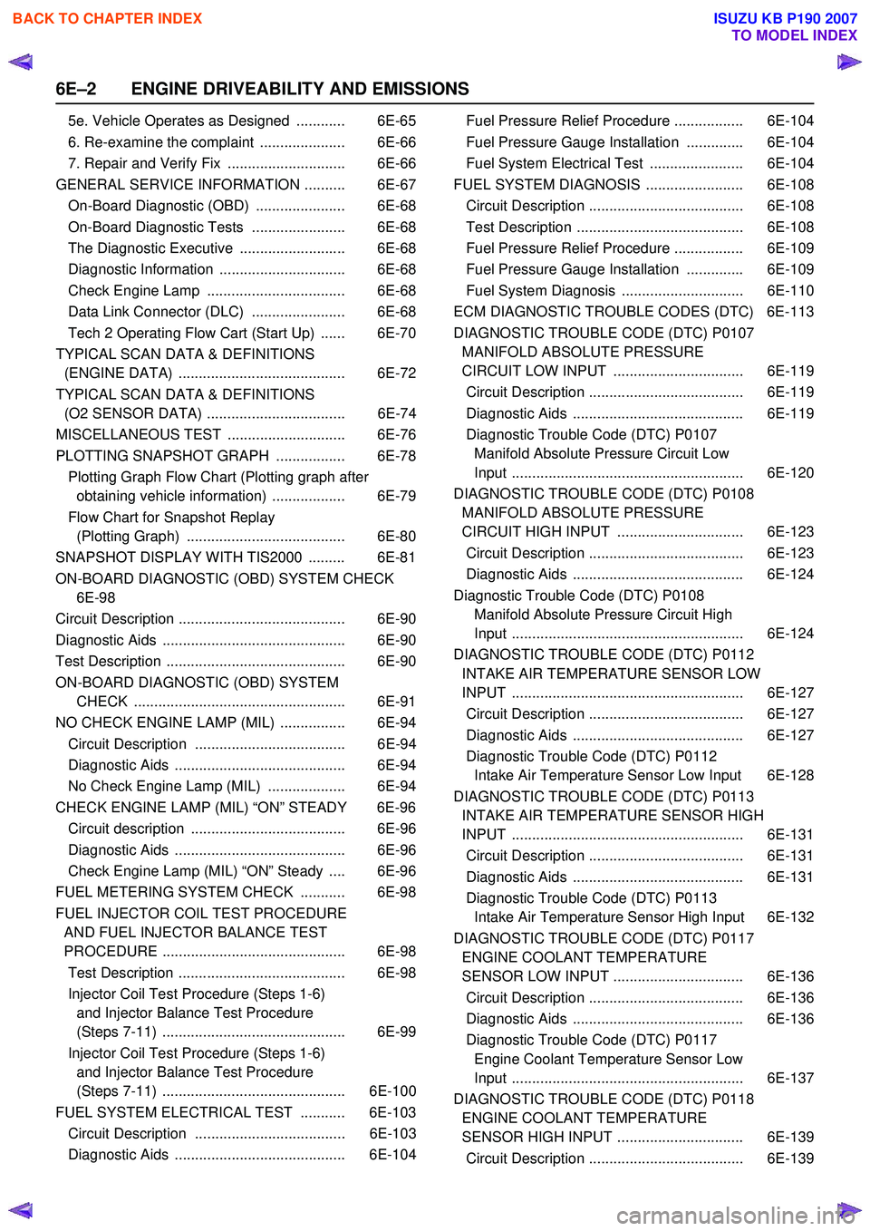
6E–2 ENGINE DRIVEABILITY AND EMISSIONS
5e. Vehicle Operates as Designed ............ 6E-65
6. Re-examine the complaint ..................... 6E-66
7. Repair and Verify Fix ............................. 6E-66
GENERAL SERVICE INFORMATION .......... 6E-67 On-Board Diagnostic (OBD) ...................... 6E-68
On-Board Diagnostic Tests ....................... 6E-68
The Diagnostic Executive .......................... 6E-68
Diagnostic Information ............................... 6E-68
Check Engine Lamp .................................. 6E-68
Data Link Connector (DLC) ....................... 6E-68
Tech 2 Operating Flow Cart (Start Up) ...... 6E-70
TYPICAL SCAN DATA & DEFINITIONS (ENGINE DATA) ......................................... 6E-72
TYPICAL SCAN DATA & DEFINITIONS (O2 SENSOR DATA) .................................. 6E-74
MISCELLANEOUS TEST ............................. 6E-76
PLOTTING SNAPSHOT GRAPH ................. 6E-78 Plotting Graph Flow Chart (Plotting graph after obtaining vehicle information) .................. 6E-79
Flow Chart for Snapshot Replay (Plotting Graph) ....................................... 6E-80
SNAPSHOT DISPLAY WITH TIS2000 ......... 6E-81
ON-BOARD DIAGNOSTIC (OBD) SYSTEM CHECK 6E-98
Circuit Description ......................................... 6E-90
Diagnostic Aids ............................................. 6E-90
Test Description ............................................ 6E-90
ON-BOARD DIAGNOSTIC (OBD) SYSTEM CHECK .................................................... 6E-91
NO CHECK ENGINE LAMP (MIL) ................ 6E-94 Circuit Description ..................................... 6E-94
Diagnostic Aids .......................................... 6E-94
No Check Engine Lamp (MIL) ................... 6E-94
CHECK ENGINE LAMP (MIL) “ON” STEADY 6E-96 Circuit description ...................................... 6E-96
Diagnostic Aids .......................................... 6E-96
Check Engine Lamp (MIL) “ON” Steady .... 6E-96
FUEL METERING SYSTEM CHECK ........... 6E-98
FUEL INJECTOR COIL TEST PROCEDURE AND FUEL INJECTOR BALANCE TEST
PROCEDURE ............................................. 6E-98
Test Description ......................................... 6E-98
Injector Coil Test Procedure (Steps 1-6) and Injector Balance Test Procedure
(Steps 7-11) ............................................. 6E-99
Injector Coil Test Procedure (Steps 1-6) and Injector Balance Test Procedure
(Steps 7-11) ............................................. 6E-100
FUEL SYSTEM ELECTRICAL TEST ........... 6E-103 Circuit Description ..................................... 6E-103
Diagnostic Aids .......................................... 6E-104 Fuel Pressure Relief Procedure ................. 6E-104
Fuel Pressure Gauge Installation .............. 6E-104
Fuel System Electrical Test ....................... 6E-104
FUEL SYSTEM DIAGNOSIS ........................ 6E-108 Circuit Description ...................................... 6E-108
Test Description ......................................... 6E-108
Fuel Pressure Relief Procedure ................. 6E-109
Fuel Pressure Gauge Installation .............. 6E-109
Fuel System Diagnosis .............................. 6E-110
ECM DIAGNOSTIC TROUBLE CODES (DTC) 6E-113
DIAGNOSTIC TROUBLE CODE (DTC) P0107 MANIFOLD ABSOLUTE PRESSURE
CIRCUIT LOW INPUT ................................ 6E-119
Circuit Description ...................................... 6E-119
Diagnostic Aids .......................................... 6E-119
Diagnostic Trouble Code (DTC) P0107 Manifold Absolute Pressure Circuit Low
Input ......................................................... 6E-120
DIAGNOSTIC TROUBLE CODE (DTC) P0108 MANIFOLD ABSOLUTE PRESSURE
CIRCUIT HIGH INPUT ............................... 6E-123
Circuit Description ...................................... 6E-123
Diagnostic Aids .......................................... 6E-124
Diagnostic Trouble Code (DTC) P0108 Manifold Absolute Pressure Circuit High
Input ......................................................... 6E-124
DIAGNOSTIC TROUBLE CODE (DTC) P0112 INTAKE AIR TEMPERATURE SENSOR LOW
INPUT ......................................................... 6E-127
Circuit Description ...................................... 6E-127
Diagnostic Aids .......................................... 6E-127
Diagnostic Trouble Code (DTC) P0112 Intake Air Temperature Sensor Low Input 6E-128
DIAGNOSTIC TROUBLE CODE (DTC) P0113 INTAKE AIR TEMPERATURE SENSOR HIGH
INPUT ......................................................... 6E-131
Circuit Description ...................................... 6E-131
Diagnostic Aids .......................................... 6E-131
Diagnostic Trouble Code (DTC) P0113 Intake Air Temperature Sensor High Input 6E-132
DIAGNOSTIC TROUBLE CODE (DTC) P0117 ENGINE COOLANT TEMPERATURE
SENSOR LOW INPUT ................................ 6E-136
Circuit Description ...................................... 6E-136
Diagnostic Aids .......................................... 6E-136
Diagnostic Trouble Code (DTC) P0117 Engine Coolant Temperature Sensor Low
Input ......................................................... 6E-137
DIAGNOSTIC TROUBLE CODE (DTC) P0118 ENGINE COOLANT TEMPERATURE
SENSOR HIGH INPUT ............................... 6E-139
Circuit Description ...................................... 6E-139
BACK TO CHAPTER INDEX
TO MODEL INDEX
ISUZU KB P190 2007
Page 2176 of 6020
6E–6 ENGINE DRIVEABILITY AND EMISSIONS
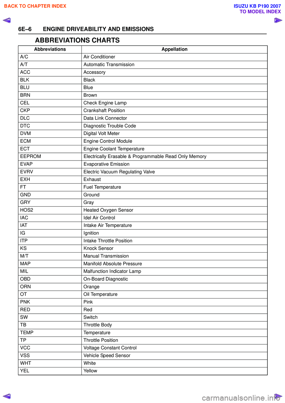
ABBREVIATIONS CHARTS
AbbreviationsAppellation
A/C Air Conditioner
A/T Automatic Transmission
ACC Accessory
BLK Black
BLU Blue
BRN Brown
CEL Check Engine Lamp
CKP Crankshaft Position
DLC Data Link Connector
DTC Diagnostic Trouble Code
DVM Digital Volt Meter
ECM Engine Control Module
ECT Engine Coolant Temperature
EEPROM Electrically Erasable & Programmable Read Only Memory
EVAP Evaporative Emission
EVRV Electric Vacuum Regulating Valve
EXH Exhaust
FT Fuel Temperature
GND Ground
GRY Gray
HOS2 Heated Oxygen Sensor
IAC Idel Air Control
IAT Intake Air Temperature
IG Ignition
ITP Intake Throttle Position
KS Knock Sensor
M/T Manual Transmission
MAP Manifold Absolute Pressure
MIL Malfunction Indicator Lamp
OBD On-Board Diagnostic
ORN Orange
OT Oil Temperature
PNK Pink
RED Red
SW Switch
TB Throttle Body
TEMP Temperature
TP Throttle Position
VCC Voltage Constant Control
VSS Vehicle Speed Sensor
WHT White
YEL Yellow
BACK TO CHAPTER INDEX
TO MODEL INDEX
ISUZU KB P190 2007
Page 2218 of 6020
6E–48 ENGINE DRIVEABILITY AND EMISSIONS
GENERAL DESCRIPTION FOR ECM AND
SENSORS
Engine Control Module (ECM)
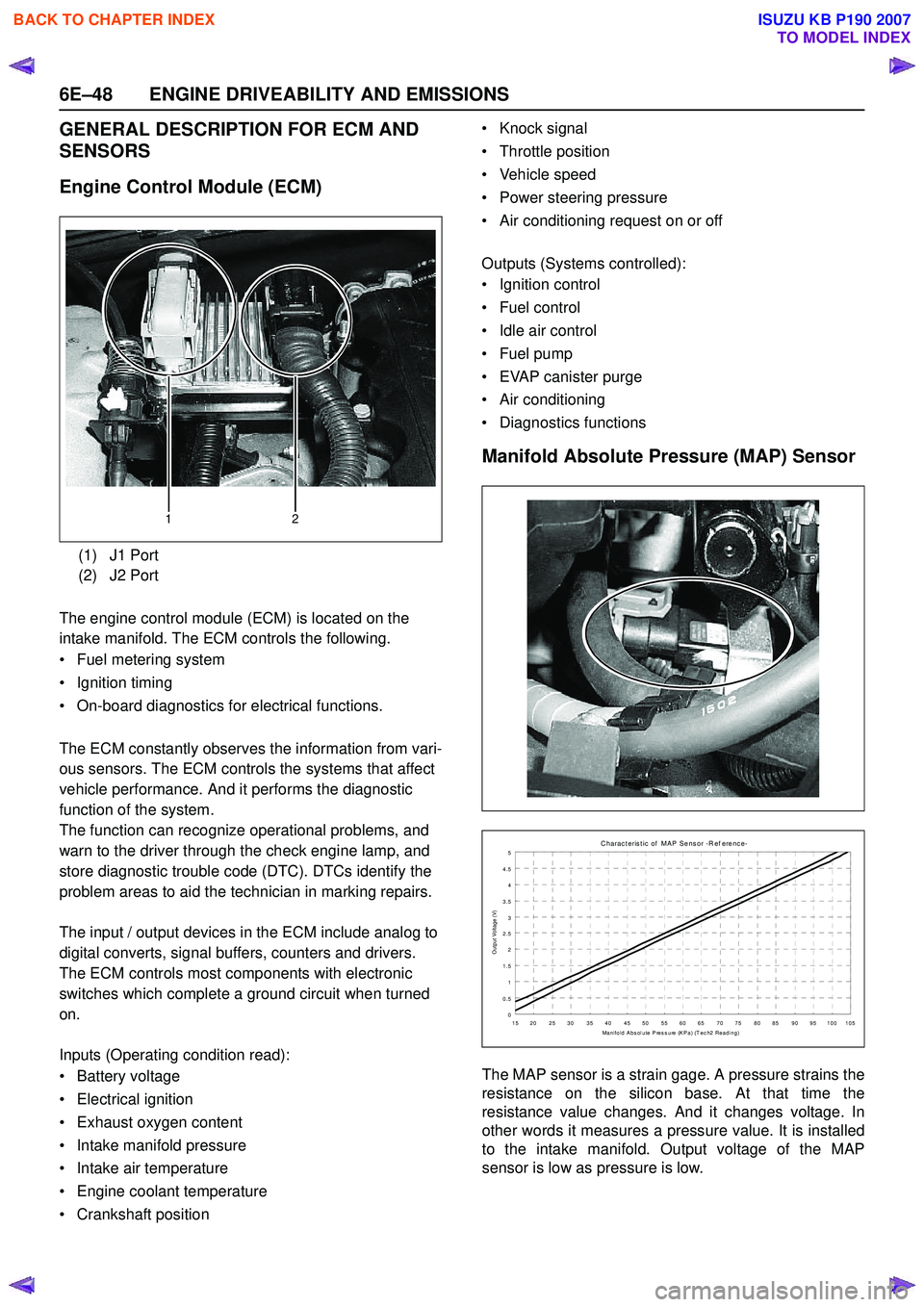
The engine control module (ECM) is located on the
intake manifold. The ECM controls the following.
• Fuel metering system
• Ignition timing
• On-board diagnostics for electrical functions.
The ECM constantly observes the information from vari-
ous sensors. The ECM controls the systems that affect
vehicle performance. And it performs the diagnostic
function of the system.
The function can recognize operational problems, and
warn to the driver through the check engine lamp, and
store diagnostic trouble code (DTC). DTCs identify the
problem areas to aid the technician in marking repairs.
The input / output devices in the ECM include analog to
digital converts, signal buffers, counters and drivers.
The ECM controls most components with electronic
switches which complete a ground circuit when turned
on.
Inputs (Operating condition read):
• Battery voltage
• Electrical ignition
• Exhaust oxygen content
• Intake manifold pressure
• Intake air temperature
• Engine coolant temperature
• Crankshaft position • Knock signal
• Throttle position
• Vehicle speed
• Power steering pressure
• Air conditioning request on or off
Outputs (Systems controlled):
• Ignition control
• Fuel control
• Idle air control
• Fuel pump
• EVAP canister purge
• Air conditioning
• Diagnostics functions
Manifold Absolute Pressure (MAP) Sensor
The MAP sensor is a strain gage. A pressure strains the
resistance on the silicon base. At that time the
resistance value changes. And it changes voltage. In
other words it measures a pressure value. It is installed
to the intake manifold. Output voltage of the MAP
sensor is low as pressure is low.
(1) J1 Port
(2) J2 Port
12
C harac t eris t ic of MAP Sens or -R ef erenc e-
0
0.5 1
1.5 2
2.5
3
3.5 4
4.5 5
15 20 25 30 35 40 45 50 55 60 65 70 75 80 85 90 95 100 105 Manifold Abs olute Press ure (KPa) (T ec h2 Reading)
Output Voltage (V)
BACK TO CHAPTER INDEX
TO MODEL INDEX
ISUZU KB P190 2007