Page 5572 of 6020
8A-634 ELECTRICAL-BODY AND CHASSIS
No. Connector face No. Connector face
X16
Black
DIODE
X17
Black
DIODE
BACK TO CHAPTER INDEX
TO MODEL INDEXISUZU KB P190 2007
Page 5582 of 6020

Cruise Control – HFV6 Page 8C–4
NOTE Defined
A NOTE statement immediately precedes or follows an operating procedure, maintenance practice or condition that
requires highlighting. A NOTE statement also emphasises necessary characteristics of a diagnostic or repair procedure.
A NOTE statement is designed to:
• Clarify a procedure,
• Present additional information for accomplishing a procedure,
• Give insight into the reasons for performing a procedure in the recommended manner, and / or
• Present information that gives the technician the benefit of past experience in accomplishing a procedure with
greater ease.
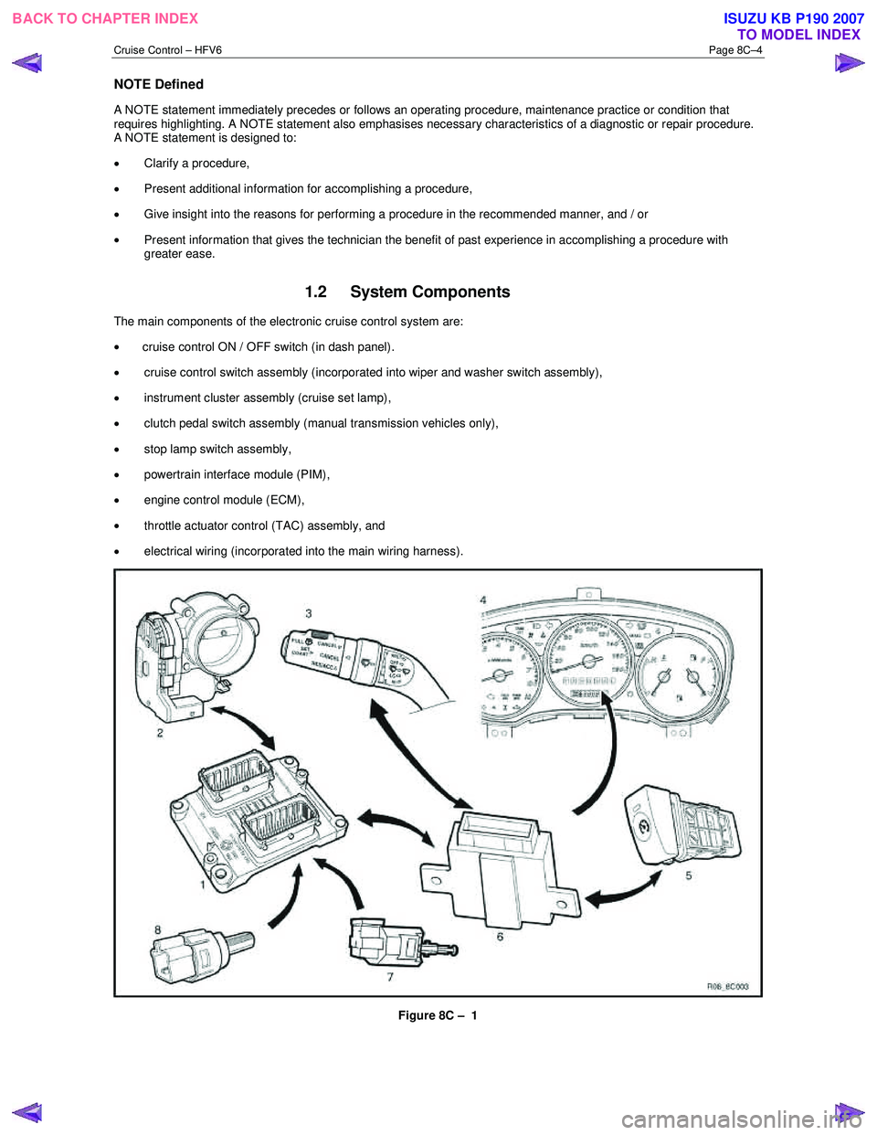
1.2 System Components
The main components of the electronic cruise control system are:
• cruise control ON / OFF switch (in dash panel).
• cruise control switch assembly (incorporated into wiper and washer switch assembly),
• instrument cluster assembly (cruise set lamp),
• clutch pedal switch assembly (manual transmission vehicles only),
• stop lamp switch assembly,
• powertrain interface module (PIM),
• engine control module (ECM),
• throttle actuator control (TAC) assembly, and
• electrical wiring (incorporated into the main wiring harness).
Figure 8C – 1
BACK TO CHAPTER INDEX TO MODEL INDEXISUZU KB P190 2007
Page 5583 of 6020

Cruise Control – HFV6 Page 8C–5
Legend
1 Engine Control Module
2 Throttle Actuator Control (TAC) Assembly
3 Cruise Control Switch Assembly
4 Instrument Cluster Assembly 5 Cruise Control ON / OFF Switch
6 Powertrain Interface Module
7 Clutch Pedal Switch Assembly (Manual Only)
8 Stop Lamp Switch Assembly
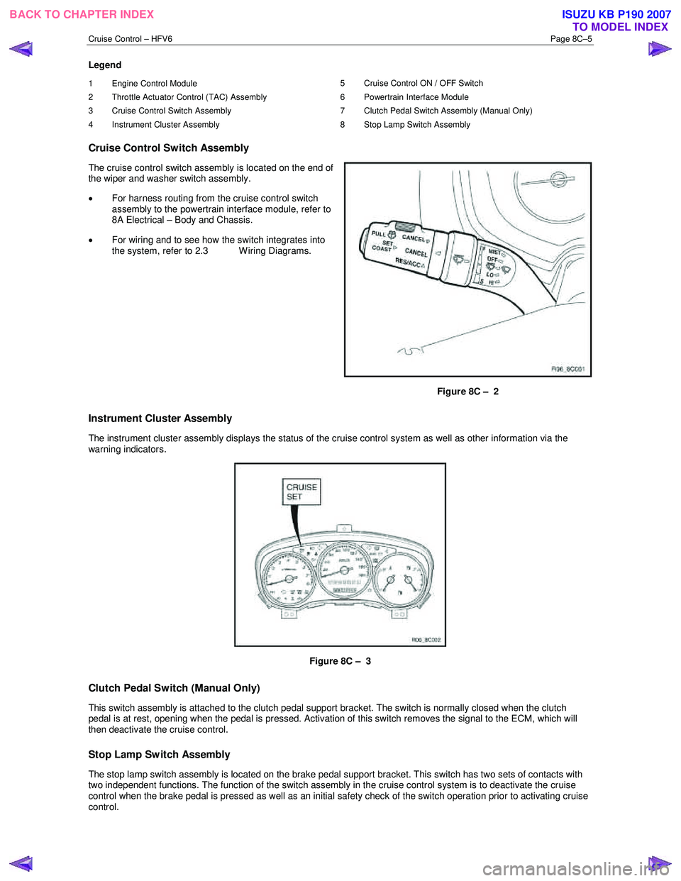
Cruise Control Switch Assembly
The cruise control switch assembly is located on the end of
the wiper and washer switch assembly.
• For harness routing from the cruise control switch
assembly to the powertrain interface module, refer to
8A Electrical – Body and Chassis.
• For wiring and to see how the switch integrates into
the system, refer to 2.3 W iring Diagrams.
Figure 8C – 2
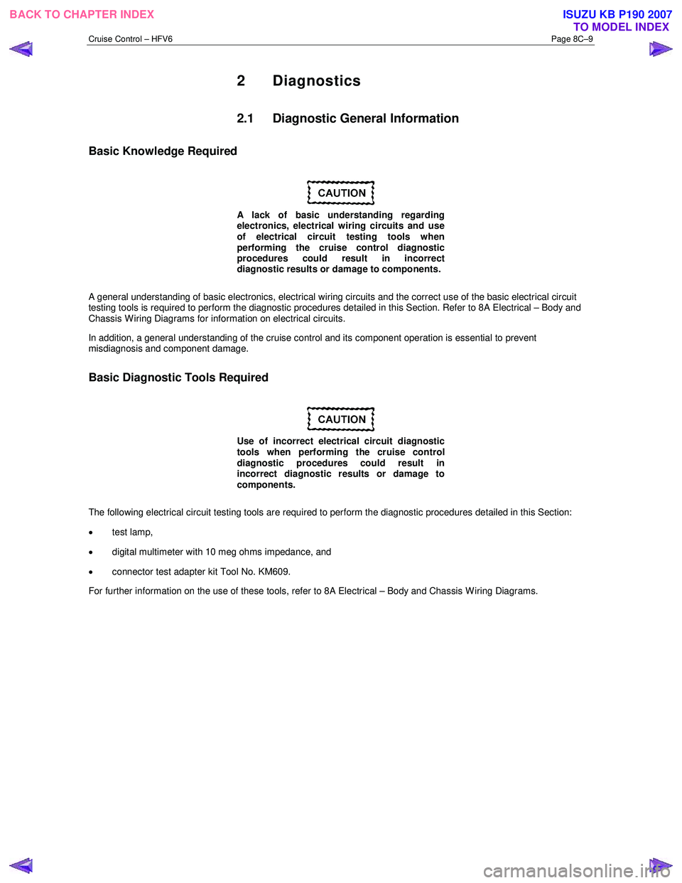
Instrument Cluster Assembly
The instrument cluster assembly displays the status of the cruise control system as well as other information via the
warning indicators.
Figure 8C – 3
Clutch Pedal Switch (Manual Only)
This switch assembly is attached to the clutch pedal support bracket. The switch is normally closed when the clutch
pedal is at rest, opening when the pedal is pressed. Activation of this switch removes the signal to the ECM, which will
then deactivate the cruise control.
Stop Lamp Switch Assembly
The stop lamp switch assembly is located on the brake pedal support bracket. This switch has two sets of contacts with
two independent functions. The function of the switch assembly in the cruise control system is to deactivate the cruise
control when the brake pedal is pressed as well as an initial safety check of the switch operation prior to activating cruise
control.
BACK TO CHAPTER INDEX TO MODEL INDEXISUZU KB P190 2007
Page 5587 of 6020

Cruise Control – HFV6 Page 8C–9
2 Diagnostics
2.1 Diagnostic General Information
Basic Knowledge Required
A lack of basic understanding regarding
electronics, electrical wiring circuits and use
of electrical circuit testing tools when
performing the cruise control diagnostic
procedures could result in incorrect
diagnostic results or damage to components.
A general understanding of basic electronics, electrical wiring circuits and the correct use of the basic electrical circuit
testing tools is required to perform the diagnostic procedures detailed in this Section. Refer to 8A Electrical – Body and
Chassis W iring Diagrams for information on electrical circuits.
In addition, a general understanding of the cruise control and its component operation is essential to prevent
misdiagnosis and component damage.
Basic Diagnostic Tools Required
Use of incorrect electrical circuit diagnostic
tools when performing the cruise control
diagnostic procedures could result in
incorrect diagnostic results or damage to
components.
The following electrical circuit testing tools are required to perform the diagnostic procedures detailed in this Section:
• test lamp,
• digital multimeter with 10 meg ohms impedance, and
• connector test adapter kit Tool No. KM609.
For further information on the use of these tools, refer to 8A Electrical – Body and Chassis W iring Diagrams.
BACK TO CHAPTER INDEX TO MODEL INDEXISUZU KB P190 2007
Page 5589 of 6020
Cruise Control – HFV6 Page 8C–11
Step Action Yes No
3 On Tech 2 select
Engine / V6 Engine / Diagnostic Trouble codes / Read DTCs’.
Are there any set DTC’s? Go to the
appropriate DTC table in 6C1-2 Engine
Management – V6 – Diagnostics Go to Step 4
4 Is the instrument cluster assembly functioning correctly? Go to 2.4
Cruise
Control Inoperative / Malfunctioning Refer to 8A
Electrical – Body
and Chassis.
When all diagnosis and repairs are completed, clear all DTCs and check the system for correct operation.
BACK TO CHAPTER INDEX TO MODEL INDEXISUZU KB P190 2007
Page 5602 of 6020
Cruise Control – HFV6 Page 8C–24
3.4 Clutch Pedal Switch (Manual Only)
Remove
1 Disconnect the electrical connector (1) from the clutch
switch (2).
2 Loosen the lock nut (3) and remove the clutch switch from the pedal bracket.
Figure 8C – 13
Test
1 Using a multimeter set to measure ohms, probe the pins (1) of the switch assembly.
2 In the neutral position (plunger extended) there should be an open circuit across the switch.
3 In the active position (plunger extended) there should be a closed circuit across the switch.
4 Replace the switch as per the following reinstall procedure if the tests prove the switch to be faulty.
5 If the test proves the switch to be serviceable, reinstall it as per the following procedure.
Figure 8C – 14
BACK TO CHAPTER INDEX TO MODEL INDEXISUZU KB P190 2007
Page 5603 of 6020
Cruise Control – HFV6 Page 8C–25
Reinstall
6 Install the clutch switch (1) as follows:
a Insert the switch into the clutch pedal bracket.
b Rotate the switch clockwise until obtaining the clearance (2) between the pedal (3) and the
pedal stoper.
Clutch pedal and pedal stoper
clearance specification............................... 0.5 – 1.5 mm
c Tighten the lock nut (4) to the correct torque specification.
Clutch switch lock nut
torque specification ............................................ 31.0 Nm
d Recheck the clutch switch clearance, readjust clearance if required.
NOTE
No adjustment is required for the clutch switch
itself.
Figure 8C – 15
7 Reconnect the electrical connector to the clutch switch.
8 Verify the operation of the clutch switch by operating the cruise control and checking the clutch switch stops operation of the cruise control when the clutch pedal is pressed.
BACK TO CHAPTER INDEX TO MODEL INDEXISUZU KB P190 2007
Page 5640 of 6020

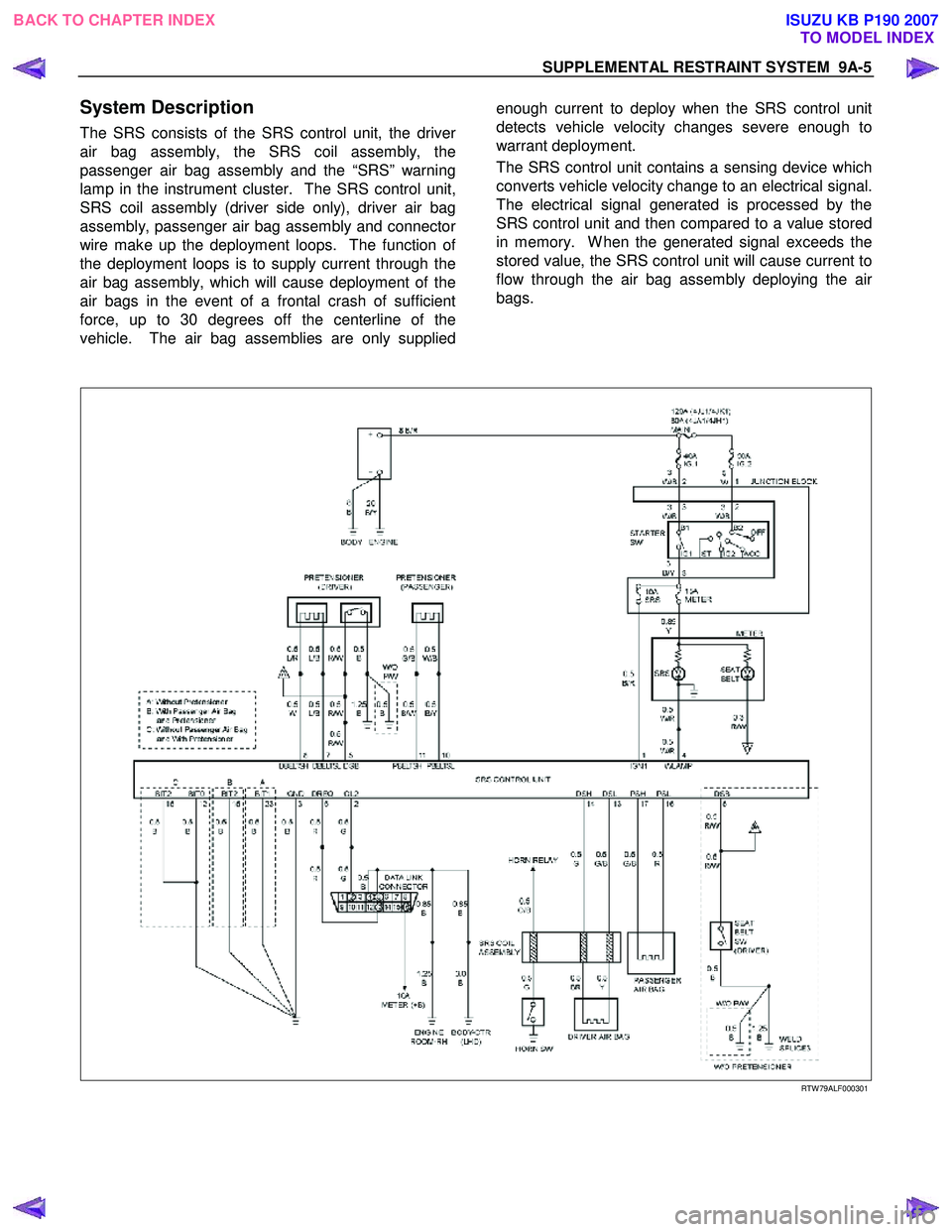
SUPPLEMENTAL RESTRAINT SYSTEM 9A-5
System Description
The SRS consists of the SRS control unit, the driver
air bag assembly, the SRS coil assembly, the
passenger air bag assembly and the “SRS” warning
lamp in the instrument cluster. The SRS control unit,
SRS coil assembly (driver side only), driver air bag
assembly, passenger air bag assembly and connecto
r
wire make up the deployment loops. The function of
the deployment loops is to supply current through the
air bag assembly, which will cause deployment of the
air bags in the event of a frontal crash of sufficient
force, up to 30 degrees off the centerline of the
vehicle. The air bag assemblies are only supplied
enough current to deploy when the SRS control unit
detects vehicle velocity changes severe enough to
warrant deployment.
The SRS control unit contains a sensing device which
converts vehicle velocity change to an electrical signal.
The electrical signal generated is processed by the
SRS control unit and then compared to a value stored
in memory. W hen the generated signal exceeds the
stored value, the SRS control unit will cause current to
flow through the air bag assembly deploying the ai
r
bags.
RTW 79ALF000301
BACK TO CHAPTER INDEX TO MODEL INDEXISUZU KB P190 2007